Sign In
Upload
Manuals
Brands
GE Manuals
Protection Device
845
GE 845 Manuals
Manuals and User Guides for GE 845. We have
2
GE 845 manuals available for free PDF download: Instruction Manual
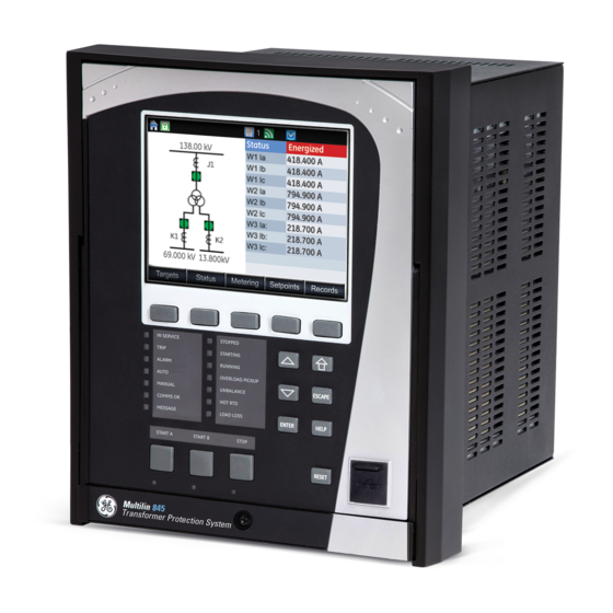
GE 845 Instruction Manual (552 pages)
Transformer Protection System
Brand:
GE
| Category:
Protection Device
| Size: 17.15 MB
Table of Contents
Table of Contents
3
INTRODUCTION Overview
11
Description of the 845 Transformer Protection Relay
12
Security Overview
17
845 Order Codes
18
Device
20
Protection
20
Specifications
20
Control
27
Monitoring
28
Recording
29
User-Programmable Elements
30
Metering
31
Inputs
33
Outputs
35
Power Supply
36
Communications
37
Testing & Certification
38
Environmental
39
Physical
39
Cautions and Warnings
40
Safety Words and Definitions
40
General Cautions and Warnings
40
Must-Read Information
43
Storage
44
For Further Assistance
44
Repairs
44
Product Identification
45
INSTALLATION Mechanical Installation
45
Dimensions
46
Mounting
47
Standard Panel Mount
48
Depth Reducing Collar
49
Draw-Out Unit Withdrawal and Insertion
51
Removable Power Supply
52
Removable Magnetic Module
53
Arc Flash Sensor
54
Sensor Fiber Handling & Storage
54
Sensor Installation
54
Electrical Installation
55
Typical Wiring Diagrams
55
Terminal Identification
60
Wire Size
64
Phase Sequence and Transformer Polarity
65
Ground CT Inputs
65
Voltage Inputs
66
Restricted Earth Fault Inputs
66
Zero-Sequence CT Installation
67
Control Power
68
Contact Inputs
68
Output Relays
69
Serial Communications
71
Irig-B
73
Graphical Display
76
INTERFACES Front Control Panel Interface
76
Output Relays
77
Working with Graphical Display
77
Single Line Diagram
80
Rugged and Membrane Front Panel Leds
82
Home Screen Icons
84
Relay Messages
85
Target Messages
85
Self-Test Errors
86
Flash Messages
89
Out of Service
89
Label Removal
89
Software Interface
91
Enervista 8 Series Setup Software
91
Hardware & Software Requirements
91
Installing the Enervista 8 Series Setup Software
92
Upgrading the Software
94
Connecting Enervista 8 Series Setup Software to the Relay
95
Using the Quick Connect Feature
95
Configuring Ethernet Communications
96
Connecting to the Relay
97
Working with Setpoints & Setpoints Files
98
Engaging a Device
99
Entering Setpoints
99
File Support
100
Using Setpoints Files
100
Adding Setpoints Files to the Environment
101
Downloading & Saving Setpoints Files
101
Creating a New Setpoints File
102
Upgrading Setpoints Files to a New Revision
103
Printing Setpoints
104
Loading Setpoints from a File
105
Printing Values from a Connected Device
105
Uninstalling Files and Clearing Data
106
Quick Setup
106
Upgrading Relay Firmware
108
Loading New Relay Firmware
109
Advanced Enervista 8 Series Setup Software Features
112
SLD Configurator
112
Flexcurve Editor
119
Transient Recorder (Waveform Capture)
120
Protection Summary
124
Offline Settings File Conversion
125
Convert SR 745 Files
125
Conversion Summary Report
127
Results Window
127
SETPOINTS Setpoints Main Menu
130
Protection and Trip Breaker Selection
130
Setpoints Entry Methods
135
Common Setpoints
135
Logic Diagrams
137
Setpoints Text Abbreviations
138
Device
139
Real-Time Clock
141
Clock
142
PTP Configuration
143
SNTP Protocol
144
Security
145
Basic Security
146
Cybersentry
148
Communications
154
Wifi
155
Ethernet Ports
158
Modbus Protocol
160
Routing
164
DNP Protocol
166
DNP / IEC104 Point Lists
169
Iec 60870-5-104
171
Iec 60870-5-103
173
Remote Modbus Device
175
Transient Recorder
176
Data Logger
178
Fault Reports
181
Event Data
182
Programmable Leds
183
Programmable Pushbuttons
184
Tab Pushbuttons
188
Annunciator
191
Display Properties
193
Default Screens
194
Home Screens
195
Resetting
196
System
198
Current Sensing
199
Power Sensing
201
Transformer
202
Transformer Setup
203
Xfmer Status Detection
228
Thermal Inputs
231
On-Load Tap Changer
232
Breakers
238
Switches
240
Flexcurves
243
Inputs
245
Virtual Inputs
248
Remote Inputs
250
Output Relays
255
Outputs
255
Auxiliary Relay Selected for Breaker Trip
258
Aux Relay Selected for Breaker Close
260
Auxiliary Output Relays
262
Critical Failure Relay #8
263
Virtual Outputs
264
Analog Outputs
264
Protection
266
Percent Differential
268
Transformer Overload
279
Current Elements
281
Inverse Time Overcurrent Curves
281
Percent of Load-To-Trip
288
Phase Time Overcurrent Protection (51P)
289
Phase Instantaneous Overcurrent Protection (50P)
292
Phase Directional Overcurrent Protection (67P)
294
Neutral Time Overcurrent Protection (51N)
297
Neutral Instantaneous Overcurrent Protection (50N)
300
Neutral Directional Overcurrent Protection (67N)
303
Ground Time Overcurrent Protection (51G)
308
Ground Instantaneous Overcurrent Protection (50G)
310
Ground Directional Overcurrent Protection (67G)
312
Restricted Ground (Earth) Fault (87G)
316
Negative Sequence Time Overcurrent Protection (51_2)
321
Negative Sequence Instantaneous Overcurrent Protection (50_2)
323
Voltage Elements
326
Undervoltage Curves
327
Phase Undervoltage Protection (27P)
328
Auxiliary Undervoltage (27X)
331
Phase Overvoltage Protection (59P)
334
Auxiliary Overvoltage Protection (59X)
337
Neutral Overvoltage Protection (59N)
340
Negative Sequence Overvoltage Protection (59_2)
343
Volts Per Hertz (24)
345
Power Elements
351
Directional Power (32)
351
Frequency Elements
357
Underfrequency (81U)
357
Overfrequency (81O)
360
Frequency Rate of Change (81R)
363
Monitoring
367
Transformer
367
Harmonic Derating
367
Thermal Elements
370
Tap Changer Failure
378
Trip and Close Circuit Monitoring
380
Breaker Arcing Current
387
Breaker Health
390
Functions
394
Power Factor (55)
394
Demand
400
Pulsed Outputs
409
Digital Counters
412
Harmonic Detection
415
RTD Temperature
418
RTD Trouble
423
Loss of Communications
424
Control
426
Local Control Mode (Breakers and Switches)
429
Breaker Control
438
Switch Control (9)
441
Virtual Input Control
444
Trip Bus
445
Breaker Failure (50BF)
447
Setup
448
Initiate
450
Arc Flash Protection
452
Synchrocheck (25)
454
VT Fuse Failure (VTFF)
459
Flexlogic
461
Timers
471
Flexlogic Equation
473
Viewing Flexlogic Graphics
475
Flexelements
476
Testing
482
Simulation
483
Pre-Fault
484
Fault
485
Test Leds
486
Ethernet Loopback Test
487
STATUS Summary
490
Annunciator
491
Breakers
492
Switches
493
Contact Inputs
494
Virtual Inputs
495
Virtual Outputs
496
Information
501
Hardware Versions
502
Device Status
503
Clock
504
METERING Summary
508
Transformer
509
Windings
510
Thermal Elements
511
Currents
512
Voltages
514
Frequency
515
Volts Per Hertz
516
Harmonics 1(Harmonics 4)
517
Harmonic Detection
518
Power
519
Energy
520
Power Factor
521
Current Demand K1
522
Directional Power
523
Rtds
524
Flexelements
525
RECORDS Events
527
Fault Reports
528
Breakers
529
Remote Modbus Device
530
Clear Records
532
M&D Device Data
535
Learned Data Records
536
Energization Records
537
Digital Fault Records
538
DGA Models
539
Historical Maximum Record
540
DGA Historical Trend
541
Environmental Health Report
543
General Maintenance
545
Warranty
547
A.APPENDIX a Warranty
548
Major Updates
548
Advertisement
GE 845 Instruction Manual (484 pages)
Transformer Protection Relay
Brand:
GE
| Category:
Relays
| Size: 13.62 MB
Table of Contents
Table of Contents
3
INTRODUCTION Overview
9
Description of the 845 Transformer Protection Relay
10
Security Overview
14
845 Order Codes
16
Specifications
18
Protection
18
Control
25
Monitoring
25
Recording
27
User-Programmable Elements
27
Metering
28
Inputs
30
Outputs
31
Power Supply
32
Communications
32
Testing & Certification
33
Physical
34
Environmental
34
Cautions and Warnings
34
Safety Words and Definitions
34
General Cautions and Warnings
35
Must-Read Information
36
For Further Assistance
37
Product Identification
39
Dimensions
39
INSTALLATION Mechanical Installation
39
Mounting
40
Standard Panel Mount
41
Draw-Out Unit Withdrawal and Insertion
42
Removable Power Supply
43
Removable Magnetic Module
44
Electrical Installation
45
Terminal Identification
50
Wire Size
54
Phase Sequence and Transformer Polarity
54
Ground CT Inputs
55
Voltage Inputs
55
Restricted Earth Fault Inputs
56
Zero-Sequence CT Installation
56
Control Power
57
Contact Inputs
58
Output Relays
58
Serial Communications
60
Irig-B
61
3 INTERFACES Front Control Panel Interface
65
Graphical Display
65
Working with Graphical Display
65
LED Status Indicators
68
Home Screen Icons
69
Relay Messages
70
Target Messages
70
Self-Test Errors
71
Flash Messages
74
Label Removal
74
Software Interface
75
Enervista 8 Series Setup Software
75
Hardware & Software Requirements
76
Installing the Enervista 8 Series Setup Software
76
Connecting Enervista 8 Series Setup Software to the Relay
79
Using the Quick Connect Feature
79
Configuring Ethernet Communications
80
Connecting to the Relay
81
Working with Setpoints & Setpoints Files
82
Engaging a Device
82
Entering Setpoints
82
File Support
84
Using Setpoints Files
84
Downloading & Saving Setpoints Files
85
Adding Setpoints Files to the Environment
85
Creating a New Setpoints File
85
Upgrading Setpoints Files to a New Revision
86
Printing Setpoints
87
Printing Values from a Connected Device
88
Loading Setpoints from a File
89
Quick Setup
89
Upgrading Relay Firmware
92
Loading New Relay Firmware
92
Advanced Enervista 8 Series Setup Software Features
94
Flexcurve Editor
94
Transient Recorder (Waveform Capture)
96
Protection Summary
100
Offline Settings File Conversion
101
Convert SR 745 Files
101
Conversion Summary Report
102
Results Window
103
4 SETPOINTS Setpoints Main Menu
106
Protection and Trip Breaker Selection
106
Setpoints Entry Methods
110
Common Setpoints
111
Logic Diagrams
112
Setpoints Text Abbreviations
113
Device
114
Real-Time Clock
114
Clock
115
PTP Configuration
116
SNTP Protocol
118
Security
118
Basic Security
120
Cybersentry
122
Communications
128
Rs485
128
Wifi
128
Usb
132
Ethernet Ports
132
Modbus Protocol
134
DNP / IEC104 Point Lists
146
Iec 60870-5-104
149
Iec 60870-5-103
151
Iec 61850
152
Transient Recorder
167
Data Logger
170
Fault Reports
173
Flex State
174
Programmable Leds
175
Programmable Pushbuttons
177
Front Panel
180
Display Properties
180
Default Screens
181
Resetting
182
Installation
182
System
183
Current Sensing
184
Voltage Sensing
186
Power Sensing
187
Power System
188
Transformer
189
Transformer Setup
190
Xfmer Status Detection
215
Thermal Inputs
218
Onload Tap Changer
219
Breakers
224
Flexcurves
226
Inputs
229
Contact Inputs
229
Virtual Inputs
232
Remote Inputs
234
Outputs
235
Output Relays
235
Auxiliary Relay Selected for Breaker Trip
237
Aux Relay Selected for Breaker Close
240
Critical Failure Relay #8
243
Virtual Outputs
243
Protection
244
Percent Differential
246
Transformer Overload
253
Current Elements
256
Inverse Time Overcurrent Curves
256
Percent of Load-To-Trip
263
Phase Time Overcurrent Protection
264
Phase Instantaneous Overcurrent Protection
267
Phase Directional Overcurrent Protection
271
Neutral Time Overcurrent Protection
274
Neutral Instantaneous Overcurrent Protection
277
Neutral Directional Overcurrent Protection
280
Ground Time Overcurrent Protection
286
Ground Instantaneous Overcurrent Protection
289
Ground Directional Overcurrent Protection
291
Restricted Ground (Earth) Fault
295
Negative Sequence Time Overcurrent Protection
301
Negative Sequence Instantaneous Overcurrent Protection
304
Voltage Elements
307
Undervoltage Curves
307
Phase Undervoltage Protection
307
Auxiliary Undervoltage
311
Phase Overvoltage Protection
314
Auxiliary Overvoltage Protection
317
Neutral Overvoltage Protection
320
Negative Sequence Overvoltage Protection
323
Volts Per Hertz
325
Power Elements
332
Directional Power
332
Frequency Elements
339
Underfrequency
339
Overfrequency
343
Frequency Rate of Change
346
Monitoring
352
Transformer
352
Harmonic Derating
352
Thermal Elements
355
Tap Changer Failure
361
Trip and Close Circuit Monitoring
363
Breaker Arcing Current
371
Breaker Health
374
Functions
379
Power Factor
379
Demand
386
Pulsed Outputs
390
Digital Counters
392
Control
397
Setpoint Group
397
Breaker Control
400
Trip Bus
406
Breaker Failure
409
Setup
410
Initiate
413
Synchrocheck
414
VT Fuse Failure
420
Flexlogic
423
Timers
431
Non-Volatile Latches
432
Flexlogic Equation
433
Viewing Flexlogic Graphics
433
Flexelements
434
RTD Temperature
441
STATUS Breakers
445
Contact Inputs
446
Output Relays
446
Virtual Inputs
446
Virtual Outputs
447
Flex State
448
Communications
448
GOOSE Rx and Tx
448
Information
449
Main CPU
449
Comms CPU
450
Hardware Versions
450
Device Status
451
Clock
451
PTP Status
452
6 METERING Transformer
455
Percent Differential Current
455
Windings
456
Thermal Elements
458
Tap Changer
458
Currents
459
Voltages
460
Frequency
462
Volts Per Hertz
462
Harmonics 1
462
Harmonics 2
463
Harmonics 3
464
Harmonics 4
464
Synchrocheck
465
Power
466
Energy
467
Current Demand J1
467
Current Demand K1
468
Current Demand K2
468
Directional Power
469
Rtds
470
RTD Maximums
471
Events
473
Transient Records
474
Fault Reports
474
Data Logger
476
Breakers
477
Breaker Arcing Current
477
Breaker Health
477
Digital Counters
478
Clear Records
478
8 Environmental Health Report
481
9 APPENDIX A Warranty
483
Revision History
483
Major Updates
483
Advertisement
Related Products
GE Multilin 850
GE 869
GE Multilin 889
GE 840081700
GE 840099800
GE 840096400
GE 840072900
GE 840104500
GE 840089100
GE 840093400
GE Categories
Refrigerator
Ranges
Microwave Oven
Air Conditioner
Dishwasher
More GE Manuals
Login
Sign In
OR
Sign in with Facebook
Sign in with Google
Upload manual
Upload from disk
Upload from URL