Panasonic G600 Service Manual
Personal cellular telephone, handheld portable, battery packs, handsfree car mount kit, easy fit car kit, hands free car kit, simple car kit, dc adaptor, dual charger, ac adaptor, data interface cable, sms interface cable
Hide thumbs
Also See for G600:
- Technical manual (45 pages) ,
- Service manual (113 pages) ,
- Service manual (108 pages)
Table of Contents
Advertisement
Quick Links
Download this manual
See also:
Technical Manual
Service Manual
G600 Personal Cellular Telephone
Issue 1
Revision 0
Order Number: MCUK980101C8
Handheld Portable
Handsfree Car Mount Kit
Hands Free Car Kit
Data Interface Cable
SMS Interface Cable
EB-G600
Battery Packs
EB-BS600
EB-BM600
EB-BL600
EB-HF600Z
Easy Fit Car Kit
EB-HF601Z
EB-HF600
Simple Car Kit
EB-KD600
DC Adaptor
EB-CD600
Dual Charger
EB-CR600
AC Adaptor
EB-CA600
EB-PA600
EB-RS600
Advertisement
Table of Contents

Related Manuals for Panasonic G600


Summary of Contents for Panasonic G600
- Page 1 Order Number: MCUK980101C8 Service Manual G600 Personal Cellular Telephone Handheld Portable EB-G600 Battery Packs EB-BS600 EB-BM600 EB-BL600 Handsfree Car Mount Kit EB-HF600Z Easy Fit Car Kit EB-HF601Z Hands Free Car Kit EB-HF600 Simple Car Kit EB-KD600 DC Adaptor EB-CD600 Dual Charger...
- Page 2 This Service Manual is copyright and issued on the strict understanding that it is not to be reproduced, copied, or disclosed to any third party, either in whole or part, without the prior written consent of Matsushita Communication Industrial UK Ltd. Every care has been taken to ensure that the contents of this manual give an accurate representation of the equipment.
-
Page 3: Table Of Contents
TABLE OF CONTENTS INTRODUCTION GENERAL DESCRIPTION OPERATING INSTRUCTIONS INSTALLATION GUIDE DISASSEMBLY/REASSEMBLY INSTRUCTIONS... - Page 4 TECHNICAL SPECIFICATIONS TEST AND MEASUREMENT CIRCUIT DIAGRAMS PCB LAYOUT DIAGRAMS 10 PARTS LIST...
-
Page 5: Warnings And Cautions
WARNINGS AND CAUTIONS WARNING The equipment described in this manual contains polarized capacitors utilising liquid electrolyte. These devices are entirely safe provided that neither a short-circuit nor a reverse polarity connection is made across the capacitor terminals. FAILURE TO OBSERVE THIS WARNING COULD RESULT IN DAMAGE TO THE EQUIPMENT OR, AT WORST, POSSIBLE INJURY TO PERSONNEL RESULTING FROM ELECTRIC SHOCK OR THE AFFECTED CAPACITOR EXPLODING. - Page 6 This page is intentionally blank...
-
Page 7: Introduction
Purpose of this Manual This Service Manual contains the information and procedures required for installing, operating and servicing the Panasonic GSM Personal Cellular Mobile Telephone system operating on the GSM Digital Cellular Network. Structure of the Manual The manual is structured to provide service engineering personnel with the following information and procedures: 1. - Page 8 INTRODUCTION This page is intentionally blank Issue 1 Section 1 MCUK980101C8 Revision 0 1 - 2 Service Manual...
-
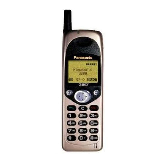
Page 9: General Description
The handportable main kit provides a standalone class 4 GSM telephone. The plug-in SIM contains the subscriber and network information necessary to operate the phone on a GSM network. Figure 1: Handportable Main Unit Kit 600-0201 IDENTIFICATION NUMBER DESCRIPTION PART NUMBER Main unit EB-G600 Battery EB-BS600 Adaptor EB-CA600 — Documentation See Section 2.13... -
Page 10: Handsfree Car Mount Kit
GENERAL DESCRIPTION Handsfree Car Mount Kit The Handsfree Car Mount Kit enables the handportable to be mounted in a vehicle, and to operate in handsfree mode. The Handsfree Unit contains a speaker, with separate volume control. Speech is via a microphone mounted on the dashboard or the sun visor. -
Page 11: Easy Fit Car Kit
GENERAL DESCRIPTION Easy Fit Car Kit The Easy Fit Car Mount Kit is very similar to the Handsfree Car Mount Kit. The main difference with the Easy Fit Car Mount kit is the addition of a cigar lighter adaptor for the supply of power. The cigar lighter adaptor makes installation of the kit very simple. -
Page 12: Simple Car Kit
GENERAL DESCRIPTION Simple Car Kit The Simple Car Kit enables the handportable unit to be powered from a vehicle battery, provided that the vehicle has a cigar lighter socket, and also has an external antenna connector for better signal quality when in a vehicle. One end of the DC adaptor plugs into the handportable with the telephone battery connected. -
Page 13: Sms Interface Cable
GENERAL DESCRIPTION SMS Interface Cable The SMS Interface Cable enables Short Text Messages (SMS) and Phonebook data to be edited, stored and created. One end of the SMS Interface Cable is connected to the standalone class 4 GSM telephone and the other end of the SMS Interface Cable is connected to the RS232 serial port on an IBM compatible PC. -
Page 14: Holder Kit
GENERAL DESCRIPTION Holder Kit The holder kit allows convenient mounting of the telephone in a vehicle. In conjunction with the DC adaptor this can make a simple car mount kit. The adjustable angle bracket and telephone holder are attached to a convenient fixing point in the vehicle. -
Page 15: Battery Packs
GENERAL DESCRIPTION 2.11 Battery Packs There is a choice of three battery packs available. The Battery Pack (S) is 400mAh (Li-Ion); the Battery Pack (M) is 650mAh (Ni-MH and the Battery Pack (L) is 1200mAh (Li-Ion). Figure 9: Battery Packs 600-0211 IDENTIFICATION NUMBER DESCRIPTION... -
Page 16: Operating Instructions
GENERAL DESCRIPTION 2.13 Documentation The following documentation packs are available and contain Operating Instructions, Quick Start information and warranty information. Some markets may require additional documentation, e.g. a specific warranty, that is not listed. DOCUMENTATION PACKS Austria G600DOCAS Belgium G600DOCBE Czech Republic G600DOCCZ Denmark... -
Page 17: Operating Instructions
OPERATING INSTRUCTIONS OPERATING INSTRUCTIONS General This section provides a brief guide to the operation and facilities available on the G600 handportable unit. Refer to the Operating Instructions for full operational information. LCD Display The G600 handportable unit has a graphical chip on glass liquid crystal display in conjunction with the following... -
Page 18: Location Of Controls
Red – charging battery pack. External connector: Used to connect to external accessories or charging equipment. Figure 2: Location of controls for G600 600-0302 Memo Key. Record a conversation for approximately 40 seconds during a call. Navigation Key. Scrolls through options or features menu and increases or decreases volume. -
Page 19: Concept Of Operation
OPERATING INSTRUCTIONS Concept of Operation There is a close relationship between the Select Key, Navigation Key and display. Figure 3: Concept of Operation 600-0303 Pressing up and down (e) will move the pointer up and down and scroll through more information in the main area of the display. -
Page 20: Features Menu Structure
OPERATING INSTRUCTIONS Incoming Calling Line Identification (CLI) When a call is received the last 6 digits of the CLI information is matched with the phonebook. Therefore an incoming call could match to the wrong phonebook entry. Features Menu Structure Figure 4: Feature Menu 600-0304 Issue 1 Section 3... -
Page 21: Call Hold
It is possible to operate all GSM telephones in the same way using the Public MMI. The following operations will work with all GSM telephones. However, this information is restricted to those operations that are supported by G600. The * and # in the following procedures should be replaced by * and #, respectively. Also <SND> and <END>... -
Page 22: Call Waiting
OPERATING INSTRUCTIONS 3.8.5 Call Waiting Enable Call Waiting * 4 3 * # <SND> Disable Call Waiting # 4 3 * # <SND> Call Waiting Status * # 4 3 * # <SND> 3.8.6 Calling Line Identification Calling Line Identification Feature Service Code Calling Line Identification Presentation (CLIP) Calling Line Identification Restriction (CLIR) -
Page 23: Call Bar
OPERATING INSTRUCTIONS 3.8.8 Call Bar Call Bar Type Service Code All outgoing calls Outgoing international calls Outgoing international calls except those to your PLMN country All incoming calls Incoming international calls when roaming * <PASSWORD> * <TELECOMMUNICATION SERVICE> # <SND> Clear # <PASSWORD>... -
Page 24: Troubleshooting
OPERATING INSTRUCTIONS Troubleshooting The user is given the following information and advised to contact the dealer if the problems persist: Problem Cause Remedy Telephone will not Check that the battery pack is fully charged and switch on correctly connected to the telephone Avoid areas of poor reception. -
Page 25: Important Error Messages
OPERATING INSTRUCTIONS 3.10 Important Error Messages The following table is a list of error messages that may occur during use of the telephone, with a description and suggested course of action: Area not Roaming in the selected area is not allowed Allowed Network Roaming with the selected network is not allowed... -
Page 26: Security Codes
OPERATING INSTRUCTIONS 3.11 Security Codes NUMBER OF CODE TYPE DESCRIPTION DIGITS Personal Identification 4 to 8 Controls SIM security. Supplied by the service provider. Number (PIN) PIN 2 4 to 8 Controls memory security. Supplied by the service provider. Used to unblock PIN and PIN 2. A PIN or PIN 2 will become blocked if the wrong PIN or PIN 2 is entered three times. -
Page 27: Gsm Network Codes And Names
OPERATING INSTRUCTIONS 3.13 GSM Network Codes and Names Access Network Country Network Operator Code Code Albania +355 Andorra +376 STA -Mobiland TELECOM Australia Australia OPTUS Communications Pty Ltd. Vodafone PTY Mobilkom Austria Austria max.mobil Azerbaijan +994 Azercell Cronet Bosnia & Herzegowina +387 PTT Bosnia Belgacom Mobile... - Page 28 OPERATING INSTRUCTIONS Ghana +233 ScanCom Gibralta +350 GIBTEL Panafon S.A Greece STET HELLAS Westel 900 GSM RT Hungary Pannon GSM RT Hong Kong Telecom CSL Ltd. Hongkong +852 Hutchison Telephone Co. Ltd. SmarTone Mobile Communications Ltd. Myanmar OMNITEL PRONTO ITALIA Italy TELECOM ITALIA MOBILE Bharti Cellular Limited...
- Page 29 OPERATING INSTRUCTIONS Malawi +265 Celcom Malaysia BINARIANG COMMUNICATIONS SDN BHD. Telenor Mobil AS Norway NetCom GSM A/S Namibia +264 New Caledonia +687 Mobilis LIBERTEL Netherlands PTT Telecom Newzealand BELLSOUTH Oman +968 General Telecoms Portugal Telecomunicaçoes Moveis Nacionais (TMN) +351 TELECEL Pakistan Mobilink Papua New Guinea...
- Page 30 OPERATING INSTRUCTIONS TELEFONICA MOVILES Spain AIRTEL SPAIN Switzerland Swiss Telecom PTT Syria +963 Mobile Syria Taiwan +886 LDTA Thailand Advanced Info Service Public Company Limited PTT Turkey Turkey PTT Turkey Tanazania +255 Tritel (United Republic of) Mobile comms Ukraine +380 Golden Telecom United Arab Emirates +971...
-
Page 31: Glossary Of Terms
OPERATING INSTRUCTIONS 3.14 Glossary of Terms Dual Tone Multiple Frequency tones. The numeric keys 0 to 9, and and # will generate DTMF different DTMF tones when pressed during conversation. These are used to access voice mail, paging and computerised home banking. Global System for Mobile communications. - Page 32 OPERATING INSTRUCTIONS This page is intentionally blank Issue 1 Section 3 MCUK980101C8 Revision 0 3 - 16 Service Manual...
-
Page 33: Installation Guide
INSTALLATION GUIDE INSTALLATION GUIDE General This section describes the procedure used to install the GSM handportable unit into a negative-grounded vehicle. Caution: Do not attempt to install this equipment into a positive-grounded vehicle. Do not attempt to supply power to the equipment from a positive-grounded vehicle. Installation will be performed using one of the following kits: 1. - Page 34 INSTALLATION GUIDE 4.2.1 Selecting the Location for the Handsfree Unit The following points should be considered when choosing a location for the handsfree unit: Ensure that the location does not obstruct normal operation/functioning of the vehicle. • Ensure that the location does not affect passenger accommodation, or is subject to excessive shocks. •...
- Page 35 INSTALLATION GUIDE 4.2.2 Wiring Locations for the handsfree unit will vary according to the type of vehicle, as will the routing of power and interconnecting cables. The following precautions should be observed: DO NOT install or connect the unit into a positive (+) grounded vehicle. This equipment must be installed into a •...
- Page 36 INSTALLATION GUIDE 4.2.3 Installation with the Adjustable Angle Bracket The Adjustable Angle Bracket can be used to install the Handsfree Unit in the following configurations: Figure 4: Adjustable angle bracket configurations 600-0404 Issue 1 Section 4 MCUK980101C8 Revision 0 4 - 4 Service Manual...
- Page 37 INSTALLATION GUIDE 4.2.4 Installing the Handsfree Microphone The following points should be considered when installing the handsfree microphone: That it does not obstruct the operation of the vehicle. That it does not affect the normal passenger accommodation. That the microphone should face the driver’s mouth, at a distance of approximately 30cm. Mounting the Microphone to the Sun Visor 1.
- Page 38 INSTALLATION GUIDE DC Adaptor The telephone is powered directly from the +12V cigar lighter socket. Switch the telephone power off and fit the DC power cable. Figure 6: DC Adaptor Installation 600-0406 Simple Car Kit The telephone is powered directly from the +12V cigar lighter socket. To improve signal quality the external antenna is connected to the FME type connector.
-
Page 39: Disassembly/Reassembly Instructions
DISASSEMBLY/REASSEMBLY INSTRUCTIONS General This section provides disassembly and reassembly procedures for the main components of the G600 system. These procedures MUST be performed by qualified service personnel, at an authorized service centre. The following warnings and precautions MUST be observed during ALL disassembly/reassembly operations: WARNING The equipment described in this manual contains polarised capacitors utilising liquid electrolyte. - Page 40 DISASSEMBLY/REASSEMBLY INSTRUCTIONS Handportable Unit 5.2.1 Disassembly 1. (Figure 1) Press the release clip, then tilt upwards to remove the battery from the telephone. Figure 1: Battery removal 600-0501 2. (Figure 2) Remove the back from the telephone case (4 screws). Figure 2: Case disassembly 600-0502 3.
- Page 41 DISASSEMBLY/REASSEMBLY INSTRUCTIONS 4. (Figure 4) Separate the RF board from the Logic board. Figure 4: RF board removal 600-0504 5. (Figure 5) Remove the screw attaching the Vibrator assembly to the Logic board (1 screw). Figure 5: Releasing the Vibrator assembly 600-00505 6.
- Page 42 DISASSEMBLY/REASSEMBLY INSTRUCTIONS 9. (Figure 7) Unplug the speaker connector from the logic PCB. Figure 7: Speaker removal 600-0508 10. (Figure 8) Gently bend the lugs on the LCD holder outwards and lift from the logic PCB. Figure 8: LCD/earpiece holder removal 600-0509 11.
- Page 43 DISASSEMBLY/REASSEMBLY INSTRUCTIONS 5.2.2 Reassembly 1. (Figure 10) Care must be taken when reinstalling the back onto the telephone case. Ensure that the securing screws are not over-tightened as this may affect the operation of the keypad. Figure 10: Case reassembly 600-0512 MCUK980101C8 Section 5...
-
Page 44: Dual Charger
DISASSEMBLY/REASSEMBLY INSTRUCTIONS Dual Charger 5.3.1 Disassembly 1. (Figure 11) Place the Dual Charger upside-down on a flat work surface. Remove the two case screws. Figure 11: Case screw removal 600-0518 2. (Figure 12) Remove the case from the cover assembly. Figure 12: Case removal 600-0519 3. - Page 45 DISASSEMBLY/REASSEMBLY INSTRUCTIONS 4. (Figure 14) Raise and tilt the charger PCB to expose the connector cable. Figure 14: Charger PCB removal (1) 600-0521 5. (Figure 15) Disconnect and remove the charger PCB. Figure 15: Charger PCB removal (2) 600-0522 MCUK980101C8 Section 5 Issue 1 Service Manual...
-
Page 46: Handsfree Unit
DISASSEMBLY/REASSEMBLY INSTRUCTIONS Handsfree Unit 5.4.1 Disassembly 1. (Figure 16) Remove the holder from the handsfree unit (2 screws). Figure 16: Holder removal 600-0513 2. (Figure 17) Remove the front cover from the handsfree assembly by removing the cover securing screw and disconnecting the speaker lead from the handsfree PCB. - Page 47 DISASSEMBLY/REASSEMBLY INSTRUCTIONS 5.4.2 Reassembly 1. (Figure 19) Reinstall the handsfree PCB into the case (3 screws). Figure 19: Handsfree PCB reinstallation 600-0516 2. (Figure 20) Position the cables into the case moulding. Figure 20: Handsfree cable positioning 600-0517 1. (Figure 21) Reinstall the front cover onto the handsfree assembly by reconnecting the speaker lead onto the handsfree PCB and reinstalling the cover securing screw.
- Page 48 DISASSEMBLY/REASSEMBLY INSTRUCTIONS 2. (Figure 22) Reinstall the holder onto the handsfree unit (2 screws). Figure 22: Holder replacement 600-0513 Issue 1 Section 5 MCUK980101C8 Revision 0 5 - 10 Service Manual...
-
Page 49: Easy Fit Unit
DISASSEMBLY/REASSEMBLY INSTRUCTIONS Easy Fit Unit 5.5.1 Disassembly 1. (Figure 21) Remove the holder from the unit (2 screws). Figure 21: Holder removal 600-0523 2. (Figure 22) Remove the back cover from the unit by removing the cover securing screw. Figure 22: Easy Fit unit, cover removal 600-0524 3. - Page 50 DISASSEMBLY/REASSEMBLY INSTRUCTIONS 5.5.2 Reassembly 1. (Figure 24) Position the cables into the case moulding; ensuring the interface cable grommet is seated securely in the case moulding and the microphone socket is also located in the case moulding. Ensure that the microphone socket is located in the case moulding Install the phone interface cable...
-
Page 51: Technical Specifications
TECHNICAL SPECIFICATIONS TECHNICAL SPECIFICATIONS General 890 - 915MHz Frequency range 935 - 960MHz Tx/Rx frequency separation 45MHz RF channel bandwidth 200kHz Number of RF channels Speech coding Full rate/Half rate Operating temperature -20°C to +55°C Handportable Unit 6.2.1 General Unless stated these specifications are with Battery Pack (EB-BS600) fitted. Battery life figures are dependent on network conditions. - Page 52 TECHNICAL SPECIFICATIONS Voice digitizing 13kbps RPE-LTP Transmission speed 270.3 kbps Diversity Frequency hopping Signal Reception Double superheterodyne 1st: 1136 - 1161 MHz Intermediate Frequency 2nd: Tx 246 MHz, Rx 201 MHz 6.2.2 Tx Characteristics 1. Frequency error: ±0.1ppm max., relative to base station frequency. 2.
- Page 53 TECHNICAL SPECIFICATIONS 5. Spurious Emissions at the Antenna Connector: Limits (dBm) Measurement Video Frequency (MHz) BW (kHz) BW (kHz) Active Mode Idle Mode Offset from carrier (in Tx band) — — Offset from Tx band edge — — — 1MHz 10.0 —...
- Page 54 TECHNICAL SPECIFICATIONS 6.2.3 Rx Characteristics 1. Sensitivity The reference sensitivity performance in terms of frame erasure, bit error, or residual bit error rates (whichever is appropriate) is specified in the following table, according to the propagation conditions. PROPAGATION CONDITIONS TU50 TU50 RA250 HT100...
- Page 55 TECHNICAL SPECIFICATIONS Handsfree Unit This specification is applicable to the Handsfree Car Kit and Easy Fit Handsfree Car Kit Input voltage 13.8V Over voltage protection 1.0V Operation: 2.0A max. (normal sound) Current consumption Idle mode: 150mA max. (no sound) Standby: 1mA max.
- Page 56 TECHNICAL SPECIFICATIONS AC Adaptor UK, EU: 230VAC ±10% Input voltage 110VAC ±10% 100VAC ±10% Input current 20mA maximum Type BF Input plug type Type C-4/C-7 Other: Country specific Output voltage 9.2VDC Output current 400mAh Ripple voltage 50mV peak to peak, at 600mAh Battery Pack (EB-BS600): Charge time Battery Pack (EB-BM600):...
- Page 57 TECHNICAL SPECIFICATIONS Battery Packs 6.7.1 Battery Pack (EB-BS600) Type Li-Ion (2 cells) Weight 44 ±2g Voltage 7.2V Capacity 400mAh Storage temperature range -20 to +40 °C (6 months) 6.7.2 Battery Pack (EB-BM600) Type Ni-MH (4 cells) Weight 75 ±2g Voltage 4.8V Capacity 650mAh...
- Page 58 6.8.2 Charging Li-Ion batteries The following points should be born in mind for the charging of Li-Ion batteries: Li-Ion batteries require a constant charge voltage of 8.4V for all G600 battery chargers (dual charger EB-CR600 and handsfree charger). Charging will be at 1.5CmA (where C is the nominal capacity of the battery). The charging current will naturally decrease to OA while the battery voltage remains constant.
- Page 59 TECHNICAL SPECIFICATIONS 6.8.3 Characteristics of Li-Ion batteries Figure 3: Voltage/Time discharge characteristics 600-0601 Figure 4: Capacity/Temperature discharge characteristics 600-0602 Figure 5: Residual Capacity/Storage Period characteristics 600-0603 MCUK980101C8 Section 6 Issue 1 Service Manual 6 - 9 Revision 0...
- Page 60 TECHNICAL SPECIFICATIONS Figure 6: Capacity/Charging Cycle characteristics 600-0605 Figure 7: Capacity/Charging Temperature characteristics 600-0604 Issue 1 Section 6 MCUK980101C8 Revision 0 6 - 10 Service Manual...
-
Page 61: External Testing
5. Section 7.6 SIM personalisation: describes the procedure to personalise the telephone to a particular SIM. External Testing The G600 unit can be connected to a compatible personal computer for electronic adjustment and fault diagnosis. This section provides a description of the equipment required to perform those tasks. - Page 62 This unit acts as a base station providing all the necessary GSM signalling requirements and also provides GSM signal measuring facilities. 7. Channel Box Software This is the test software for the G600 unit and should be installed onto the personal computer used for testing. Issue 1 Section 7...
-
Page 63: Complete Unit Test Setup
TEST AND MEASUREMENT Complete Unit Test Setup Figure 4: Complete unit test setup 600-0705 MCUK980101C8 Section 7 Issue 1 Service Manual 7 - 3 Revision 0... - Page 64 4. RS232 interface cable (9 pin straight through connection) 5. GSM test station Figure 5 shows a typical setup for testing the G600 unit. The channel box software (supplied on floppy disk) should be installed onto the main drive of the personal computer.
- Page 65 TEST AND MEASUREMENT 2. Ensure that the following settings are made: a) Interface box IFB002 Power: UP position IGN: DOWN position Mode UP position Voltage Dependent upon operation: 7.2V for Lithium Ion battery 5.6V for PCB testing 4.8V for Nickel Metal Hydride battery b) Power supply +12V DC: c) PC...
- Page 66 TEST AND MEASUREMENT 2. Ensure that the following settings are made: Interface box IFB002 Power: DOWN position IGN: DOWN position HH/HF: DOWN HH position MODE: UP position Power supply +12V DC: Channel box software loaded and the screen indicating as shown (figure 8): Figure 8: PC Screen (SCRN9) 600-0720 3.
-
Page 67: Channel Box Test Commands
TEST AND MEASUREMENT Channel Box Test Commands The following table outlines the commands available using the channel-box software. After the handheld unit has been switched on (section 7.3), use the up/down scroll keys on the personal computer keyboard to select the channel-box command. Use the left/right scroll keys to display the required indication and press the ENTER key to select the displayed function. - Page 68 TEST AND MEASUREMENT CHANNEL BOX COMMAND INDICATION FUNCTION <LED R> Switches on Incoming LED <LED B> Switches on Backlight LEDs <CHARGE ON> Switches charge sequence on LCD CONTROL OUT <LED C> Switches on Charging LED <HF ON> Switches on handsfree mode <ALL OFF>...
-
Page 69: Adjustment Mode
The adjustment data selected during calibration is stored in the telephone EEPROM. NOTE: As G600 has two battery types available, Lithium Ion and Nickel Metal Hydride, all calibration procedures must be carried out for each battery type. Figure 10: Test software screen 600-0721 7.5.1 Ramping Gain... - Page 70 TEST AND MEASUREMENT Target Peak Power Tolerance Initial Calibration Value Change per dB Power Level (dBm) (dB) PL18 ±5 1.89 2.04 PL19 ±5 1.67 1.72 Calibration of output power on each power level To be able to calibrate the ramping gain it is first necessary to switch the unit into Test Mode (section 7.3). This procedure must be followed for all power levels PL5-PL19, for low, medium and high channels: 1.
- Page 71 TEST AND MEASUREMENT 5. (Figure 13) Select VIEW TRIM PL MCH, and make a note of this value. Figure 13: Power level view 2 600-0724 6. Perform the following calculation: Set RGAIN - PL% = Value recorded in step 5 (± change in PL to meet specified value for change per dB). Make a note of the result.
- Page 72 TEST AND MEASUREMENT 9. (Figure 16) Highlight the PL5 field and press ENTER. Figure 16: Power level selection 3. 600-0728 10. Enter the value calculated in step 6 into the data field and then press ENTER. 11. Press ESC. 12. At the GSM test unit re-measure the peak power. 13.
- Page 73 TEST AND MEASUREMENT 7.5.2 RSSI This procedure describes the calibration of RSSI on the mid channel (Mch = Ch 62). This process must be carried out for Low Channel, Mid Channel and High Channel. The following channel settings are used in this procedure: 1.
- Page 74 TEST AND MEASUREMENT 8. (Figure 19) Select TRIM OTHER and make a note of the RSSI on the measured channel reading. Figure 19: RSSI reading 2. 600-0731 9. Press ESC. 10. (Figure 20) At the Channel box press F6 to program data. Figure 20: RSSI reading 3.
- Page 75 TEST AND MEASUREMENT 13. Press ENTER. 14. Press ESC. 15. Measure the RSSI level again by highlighting the RSSI dBm field and press ENTER. 16. Steps 6 to 15 must be repeated for both LOW and HIGH channels. 7.5.3 I and Q Values NOTE: With the I, Qch adjustment procedures the transmitter must be set to Power Level 5 (this presents the worst case of non-linearity) so care must be taken that the spectrum analyser used can accept a signal input of 33dBm.
- Page 76 TEST AND MEASUREMENT 2. (Figure 23) On the spectrum analyser measure the carrier leakage ratio. Carrier leakage ratio is measured as the ratio of peak power and the power at 68kHz below peak frequency. Example: peak power (902.468MHz) = 33dBm power at 68kHz below peak power = 0dBm carrier leakage ratio = 33dBm - 0dBm = 33dBm Figure 23: Carrier leakage ratio...
- Page 77 TEST AND MEASUREMENT 3. (Figure 26) Select Ich OFFSET Figure 26: I,Q data field selection 3. 600-0738 4. (Figure 27) Enter 147 for Ich OFFSET and press ENTER. Figure 27: I,Q data field selection 4. 600-0739 5. Using the Spectrum Analyser, measure the new carrier leakage ratio. 6.
- Page 78 TEST AND MEASUREMENT Qch Check 1. Set Ich offset to 127. 2. Set Qch offset to 147. a) At the Channel box press F6. b) (Figure 26) Press move down arrow until QCH OFFSET appears in the field. Press ENTER. c) (Figure 27) Enter 3 into the data field and press enter.
- Page 79 TEST AND MEASUREMENT I, Qch Gain IMPORTANT: I, Qch offset calibration should be done before this calibration. Spectrum Analyser Setup. centre frequency = 902.4MHz RBW = 10kHz VBW = 1kHz span = 1MHz sweep time = 2sec 1. Set the Channel box controls to channel 62 at power level 5, normal burst modulated with all 0’s. a) Press the down arrow until CHANGE CH >...
- Page 80 TEST AND MEASUREMENT 7.5.4 Simple Receiver Test The following procedure gives a method by which the Unit Under Test (UUT) can be placed into a condition allowing the service technician to probe the entire receive RF path. Input level and frequency can also be specified. To perform the following procedure the UUT must first be placed into Test Mode.
-
Page 81: Lock Code
TEST AND MEASUREMENT Lock Code NOTE: See section 7.2.1 for a list of the equipment and setup procedures required to perform the following adjustment and calibration procedures. To perform the following procedures the UUT must be placed into Test Mode. 7.6.1 Check current lock code 1. -
Page 82: Sim Personalisation
7.7.2 Testing To test a personalised G600, when the user has not supplied the SIM, a SIM configured for test purposes (e.g. test SIM or soft SIM) should be used. The mobile will recognise that the SIM is for testing purposes only and operate as normal. - Page 83 TEST AND MEASUREMENT 7.7.5 Enabling Procedure 1. 5 2 8 2 4 B B 2. F e to point at; “SIM” for SIM Personalisation ”Network” for Network Personalisation “Subnetwork” for Subnetwork Personalisation ”SP” for Service Provider Personalisation or ”Corporate” for Company Personalisation 600-0707 3.
- Page 84 TEST AND MEASUREMENT This page is intentionally blank Issue 1 Section 7 MCUK980101C8 Revision 0 7 - 24 Service Manual...
-
Page 85: Circuit Diagrams
CIRCUIT DIAGRAMS CIRCUIT DIAGRAMS Handheld Unit 8.1.1 RF The waveforms shown below relate to the RF circuit diagrams on the following pages. The waveforms shown are for reference purposes only. Figure 1: WF1 600-0802 Figure 2: WF2 600-0803 Figure 3: WF3 600-0804 MCUK980101C8 Section 8... - Page 86 CIRCUIT DIAGRAMS Figure 4: WF4 600-0805 8.1.2 Logic The waveform shown below relates to the logic circuit diagram on the following pages. The waveform is for reference purposes only. Figure 5: WF5 600-0801 Issue 1 Section 8 MCUK980101C8 Revision 0 8 - 2 Service Manual...
- Page 87 CIRCUIT DIAGRAMS EG70607h MCUK980101C8 Section 8 Issue 1 Service Manual 8 - 3 Revision 0...
- Page 88 CIRCUIT DIAGRAMS Logic EG70638h Issue 1 Section 8 MCUK980101C8 Revision 0 8 - 4 Service Manual...
- Page 89 Handsfree EG70696d...
- Page 90 Easy-Fit Handsfree EG70716f...
-
Page 91: Pcb Layout Diagrams
PCB LAYOUT DIAGRAMS Handheld Unit 9.1.1 RF EG70607h - back EG70638h - front... - Page 92 9.1.2 Logic EG70638h - back EG70638h - front...
- Page 93 Handsfree EG70696d - back EG70696d - front...
- Page 94 Easy-Fit Handsfree EG70716f - front (Single sided)
-
Page 95: Parts List
PARTS LIST 10 PARTS LIST 10.1 Handheld Unit Ref. Parts No Name G600RFAS01 Assembled RF PCB G600LOGAS01 Assembled Logic PCB G600CVR01G Cover Assy – Black G600CVR01B Cover Assy – Blue A0101 AA70048A LCD Module B370 BD70025A Vibrator Motor Assembly E151 AN70073A Fixed Antenna HH70007A... - Page 96 PARTS LIST 10.2 Handsfree Unit Ref. Parts No Name M0401 5N70086A Cover M0402 6V10031A Speaker net Speaker M0403 4R8209B packing Speaker M0404 1B70071A bracket M0405 XTB256GFX Screw (x2) –M0406 M0410 5M70076A Case M0411 1BC5819A Plate M0412 7X70119A Name plate M0413 XSB35FX Screw M0420...
-
Page 97: Handheld Replacement Parts List
10.3 Handheld Replacement Parts List Model : EB-G600 NAME : Logic Remarks Reference Part Number Description 10.3.1 Logic C0429 YGM1F105Z1AT CAP CERAMIC 1UF 10V SM 1608 C0430 YGM1F105Z1AT CAP CERAMIC 1UF 10V SM 1608 Model : EB-G600 NAME : Logic... - Page 98 CAP 100nF +/-10% 16V X7R SM 0603 DS0427 MAZS0470GL ZENER DIODE 4V7 SM 1608 C0528 ECUV1C104KBV CAP 100nF +/-10% 16V X7R SM 0603 FLASH G600ROM01 G600 FLASH ROM (PROGRAMMED) C0529 ECUV1H103KBV CAP 10nF +/-10% 50V X7R SM 0603 J0401 528931890 CONNECTOR 18WAY MOLEX D0401 YDRTU0005...
- Page 99 CHIP RESISTOR 1K8 OHM +/-5% 1/16W SM R0419 ERJ3GEYJ182V LOGIC G600LOG01 G6 LOGIC SIDE 1 COMPLETE 1608 G600MICPA01 G600 HANDHELD MICROPHONE ASSEMBLY CHIP RESISTOR 3K3 OHM +/-5% 1/16W SM R0419 ERJ3GEYJ332V 1608 P0403 PAMU00001 2 PIN 700 mA CONNECTOR CHIP 2 RESISTOR ARRAY 330 OHM +/-5%...
- Page 100 R0523 ERJ2GE0R00X CHIP RESISTOR 0 OHM 1/16W SM 1005 R0452 ERJ2GEJ331X CHIP RESISTOR 330 OHM 1005 +/-5% 1/16W RECEIVER G600RECPA01 G600 RECEIVER PRE-ASSEMBLY R0453 ERJ2GEJ331X CHIP RESISTOR 330 OHM 1005 +/-5% 1/16W GSM BASEBAND CONTROLLER (GEMMINI) U0401 YF711801 TQFP144 R0454...
- Page 101 Model : EB-G600 NAME : Logic Remarks Reference Part Number Description U0505 YRN5RZ30BATL VOLTAGE REGULATOR 3.0V U0506 YRN5RZ30BATL VOLTAGE REGULATOR 3.0V U0507 YURIH0028 VOLTAGE REGULATOR 2.7V YTCM4400 GSM/DCS BASEBAND/RF IF (VEGA3) TQFP80 MCUK980101C8 Section 10 Issue 1 Service Manual 10 - 7...
- Page 102 10 - 8 Service Manual 10.3.2 RF MODEL: NAME : EB-G600 Reference Part Number Description Remarks BARE-PCB EG70607G G600 RF BARE PCB MODEL: NAME : EB-G600 C0130 ECUV1H101JCV CAP 100pF +/-5% 50V NPO SM 0603 Reference Part Number Description Remarks C0133 YGM1C030C1HT CAPACITOR 3PF 1608 +/- .25PF 50V...
- Page 103 EB-G600 EB-G600 Reference Part Number Description Remarks Reference Part Number Description Remarks BARE-PCB EG70607G G600 RF BARE PCB BARE-PCB EG70607G G600 RF BARE PCB C0211 ECUV1H101JCV CAP 100pF +/-5% 50V NPO SM 0603 C0253 YGM1C070D1HT CAPACITOR C0212 ECUV1H101JCV CAP 100pF +/-5% 50V NPO SM 0603...
- Page 104 NAME : EB-G600 EB-G600 Reference Part Number Description Remarks Reference Part Number Description Remarks BARE-PCB EG70607G G600 RF BARE PCB BARE-PCB EG70607G G600 RF BARE PCB CAPACITOR 10uF + - 20% 10V TANTALUM C0361 YGM1C070D1HT CAPACITOR C0329 YCSJ3002M106 TMCM-A C0362 ECUV1H101JCV...
- Page 105 L0307 ELJRE39NJF2 INDUCTOR 39nH +/-5% SM1608 J0001 JA70047A G600 I/O CONNECTOR LS0390 HB70010A G600 BUZZER J0003 JAMU00001 G600 2 PIN 700mA CONNECTOR M0112 5X70020A VIBRATOR BUSHING (CUSHION) G600 L0101 ELJRE39NJF2 INDUCTOR 39nH +/-5% SM1608 M0113 5Y70110A G600 VIBRATOR HOLDER L0102...
- Page 106 Reference Part Number Description Remarks Reference Part Number Description Remarks BARE-PCB EG70607G G600 RF BARE PCB BARE-PCB EG70607G G600 RF BARE PCB CHIP RESISTOR 3K9 OHM +/-5% 1/16W SM CHIP RESISTOR 560 OHM +/-5% 1/16W SM R0102 ERJ2GEJ392X R0156 ERJ2GEJ561X...
- Page 107 Reference Part Number Description Remarks Reference Part Number Description Remarks BARE-PCB EG70607G G600 RF BARE PCB BARE-PCB EG70607G G600 RF BARE PCB CHIP RESISTOR 27K OHM +/-5% 1/16W SM CHIP RESISTOR 15 OHM +/-5% 1/16W SM R0265 ERJ2GEJ273X R0311 ERJ2GEJ150X...
- Page 108 CHIP RESISTOR 56 OHM +/-5% 1/16W SM R160 ERJ2GEJ560X 1005 RF PCB G600RF02 G6 RF SIDE 1 & 2 COMPLETE RF PCB G600RF01 G600 RF SIDE 1 COMPLETE S0370 SY70049A G600 SM REED SWITCH U0101 YUALW0001 IC SINGLE OP AMP +/-6V DC SSOP5-P U0102 YPMB2240F...
-
Page 109: Handsfree Replacement Parts List
LCD MODULE G600 Ref. Part No. Description Remarks E0151 AN70073A FIXED ANTENNA C0101 ECA1HFQ330 CAPACITOR 1µF FLEXI EF70037A G600 BUZZER ASSEMBLY FLEXI C0102 EEUFA1H121E CAPACITOR 1µF LOGIC G600LOGAS01 G600 LOGIC COMPLETE M0108 5S70070A LCD BACKLIGHT G600 C0103 ECA1CFQ121 CAPACITOR 120nF... - Page 110 Issue 1 Section 10 MCUK980101C8 Revision 0 10 - 16 Service Manual EB-HF600 EB-HF600 MODEL NAME: MODEL NAME: Handsfree Unit Handsfree Unit EB-HF450 EB-HF450 Ref. Part No. Description Remarks Ref. Part No. Description Remarks C0308 ECEV1CG100GR CAPACITOR 10µF C0352 YGM1C100D1HT CAPACITOR 10pF C0309...
- Page 111 EB-HF600 EB-HF600 MODEL NAME: MODEL NAME: Handsfree Unit Handsfree Unit EB-HF450 EB-HF450 Ref. Part No. Description Remarks Ref. Part No. Description Remarks D0103 YSFPB64V DIODE P0202 JA70028A CONNECTOR D0104 YSFPB64V DIODE P0203 DF116DP2DSA CONNECTOR 6WAY D0107 MA7100ATR DIODE P0300 PAPS00218 CONNECTOR D0201 YRM3LF014102...
- Page 112 Issue 1 Section 10 MCUK980101C8 Revision 0 10 - 18 Service Manual EB-HF600 EB-HF600 MODEL NAME: MODEL NAME: Handsfree Unit Handsfree Unit EB-HF450 EB-HF450 Ref. Part No. Description Remarks Ref. Part No. Description Remarks R0117 ERJ3GEYJ102V RESISTOR R0302 ERJ3GEYJ681V RESISTOR R0118 ERJ3GEYJ223V RESISTOR...
- Page 113 EB-HF600 EB-HF600 MODEL NAME: MODEL NAME: Handsfree Unit Handsfree Unit EB-HF450 EB-HF450 Ref. Part No. Description Remarks Ref. Part No. Description Remarks R0333 ERJ3GEYJ104V RESISTOR R0365 ERJ3GEYJ103V RESISTOR 100k R0334 ERJ3GEYJ104V RESISTOR R0366 ERJ3GEYJ103V RESISTOR 100k R0335 ERJ3GEYJ222V RESISTOR R0367 ERJ3GEYJ472V RESISTOR 2.2k...
- Page 114 Issue 1 Section 10 MCUK980101C8 Revision 0 10 - 20 Service Manual EB-HF600 EB-HF600 MODEL NAME: MODEL NAME Handsfree Unit Mechanical EB-HF450 EB-HF450 Ref. Part No. Description Remarks Ref. Part No. Description Remarks M0425 5FJ5129AB VOLUME KNOB W0001 WP70005AZ POWER SUPPLY CABLE M0426 XYN3J6FX SCREW...
- Page 115 MODEL NAME EBM1177 Microphone Adjustable Angle MODEL NAME EBN0002 Bracket Ref. Part No. Description Remarks Ref. Part No. Description Remarks M0103 4R13358 MIC CUSHION M0701 3G24152B BRACKET M0104 7C10096A MIC NAME PLATE M0702 XVG4X8FZ SCREW M0105 7C10096A MIC NAME PLATE M0703 XWA4FXK SPRING WASHER...
-
Page 116: Printed Material
Issue 1 Section 10 MCUK980101C8 Revision 0 10 - 22 Service Manual 10.5 Printed Material Part numbers for documentation are shown on page 2-8 (General Information). 10.6 Dual Charger The Dual Charger is not a serviceable item. 10.7 DC Adaptor The DC Adaptor is not a serviceable item.