Table of Contents
Advertisement
Advertisement
Table of Contents

Related Manuals for Bosch MIC IP PSU


Summary of Contents for Bosch MIC IP PSU
- Page 1 MIC Series IP Power Supply MIC IP PSU User Manual...
-
Page 3: Table Of Contents
Basic Mode: Encoder Basic Mode: System Overview Advanced Mode: General Identification 4.10 Password 4.11 Date/Time 4.12 Display Stamping 4.13 Advanced Mode: Web Interface 4.14 Appearance 4.15 LIVEPAGE Functions 4.16 Logging Bosch Security Systems, Inc. User Manual F.01U.265.804 | 1.6 | 2012.08... - Page 4 4.49 Advanced Mode: Service 4.50 Maintenance 4.51 Licenses 4.52 System Overview 4.53 Function test Operation Function test The LIVEPAGE Saving snapshots Recording video sequences Running recording program Processor load F.01U.265.804 | 1.6 | 2012.08 User Manual Bosch Security Systems, Inc.
- Page 5 General malfunctions Fiber Optic Module Malfunctions with iSCSI connections LEDs Processor load Network connection 6.10 Terminal block 6.11 Communication with terminal program 6.12 Transfer and disposal 6.13 Repairs 6.14 Copyrights Bosch Security Systems, Inc. User Manual F.01U.265.804 | 1.6 | 2012.08...
-
Page 6: Safety
Legal Information Copyright - This manual is the intellectual property of Bosch Security Systems, Inc. and is protected by copyright. All rights reserved. Trademarks - All hardware and software product names used in this document are likely to be registered trademarks and must be treated accordingly. -
Page 7: Important Safety Instructions/Notices
Modifications - Any change or modification of the equipment, not expressly approved by Bosch, could void the warranty or, in the case of an authorization agreement, authority to operate the equipment. - Page 8 The user may find the following booklet, prepared by the Federal Communications Commission, helpful: How to Identify and Resolve Radio-TV Interference Problems. This booklet is available from the U.S. Government Printing Office, Washington, DC 20402, Stock No. 004- 000-00345-4. F.01U.265.804 | 1.6 | 2012.08 User Manual Bosch Security Systems, Inc.
- Page 9 Certification does not cover the performance or reliability of the security or signaling aspects of this product. UL MAKES NO REPRESENTATIONS, WARRANTIES, OR CERTIFICATIONS WHATSOEVER REGARDING THE PERFORMANCE OR RELIABILITY OF ANY SECURITY OR SIGNALING RELATED FUNCTIONS OF THIS PRODUCT. Bosch Security Systems, Inc. User Manual F.01U.265.804 | 1.6 | 2012.08...
-
Page 10: Product Description
For remote control of external units such as pan or tilt heads for cameras or motorized zoom lenses, control data is transmitted via the encoder's bidirectional serial interface. This interface can also be used to transmit transparent data. F.01U.265.804 | 1.6 | 2012.08 User Manual Bosch Security Systems, Inc. -
Page 11: Summary Of Functions
Authentication according to international standard 802.1x – Bidirectional audio (mono) for line connections; transmitted in sync with the video signal – Audio encoding to international standards G.711 or L16 Bosch Security Systems, Inc. User Manual F.01U.265.804 | 1.6 | 2012.08... -
Page 12: Installation
A provision for driving various optional interface cards mounted internally to the MIC power supply enclosure (for example, an 8-input alarm card (MIC-ALM)) – A provision for a signal interface card (MIC-BP4) to connect telemetry to Bosch Biphase equipment –... -
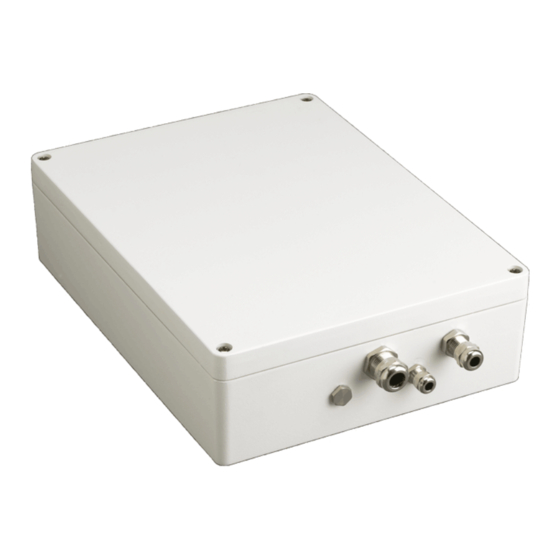
Page 13: Dimensions And Layout Of Mic Ip Power Supplies
The figures below display the dimensions and the layout of the enclosures of the MIC IP PSUs. Figure 3.1 Layout of MIC IP PSU (Model numbers: MIC-IP-PS-115, MIC-IP-PS-230, MIC-IP-PS-24) Figure 3.2 Layout of MIC IP IR PSU (Model numbers: MIC-IPIR-PS-115, MIC-IPIR-PS-230, MIC-IPIR-PS-24) -
Page 14: Mic Power Supply Units (Psus) For Non-Ir Mic Cameras
Plug in Earth Link Earth Link Fuse 2 - Primary protection Fuse 1 - MIC camera protection -- Fuse 3 - Heater protection 1 Fuse 5 - Heater protection 2 F.01U.265.804 | 1.6 | 2012.08 User Manual Bosch Security Systems, Inc. -
Page 15: Mic Power Supply Units (Psus) For Ir Mic Cameras
If fiber optics or other indirect connections are used to get data and video to and from the control room, then the Earth Link should be left intact, as long as it is the only camera-end earth reference point. Bosch Security Systems, Inc. User Manual F.01U.265.804 | 1.6 | 2012.08... -
Page 16: Fuse Ratings
Replace only with the same type and rating of fuse for continued protection against the risk of fire, damage or injury. Fitting fuses other than those described above invalidates the product warranty and may result in damage to the product or injury to the installer. F.01U.265.804 | 1.6 | 2012.08 User Manual Bosch Security Systems, Inc. -
Page 17: Installation Instructions
® Electrical Code (NEC)), Canadian Electrical Code, Part I (also called CE Code or CSA C22.1), and all applicable local codes. Bosch Security Systems, Inc. accepts no liability for any damages or losses caused by incorrect or improper installation. DANGER! –... - Page 18 Locate the four (4) mounting holes of the PSU (see Figure 3.5). The dimensions shown are for the mounting holes only. The other four (4) holes shown are for securing the lid. Figure 3.5 MIC IP PSU Mounting Dimensions Drill four (4) holes in the mounting surface for the mounting anchors appropriate for M6 screws (not supplied).
- Page 19 M6, UL-certified) of the ring terminal and crimp it in place. Note: The graphic in the figure referenced below is representative of the connections; the layout of the MIC IP PSU differs slightly from that depicted below. 14. Place the ring terminal onto the earth termination post.
- Page 20 22. Connect the RJ45 plug of the cable to the ETH socket on the encoder to connect the encoder to the network. Note: If installing a fiber optic module, see the Fiber Optic Media Converter Installation Guide for instructions for installing the module in the MIC IP PSU. F.01U.265.804 | 1.6 | 2012.08 User Manual...
- Page 21 Orange LED lights up during data transmission ETH RJ45 socket for connecting to an Ethernet LAN (local network), 10/100 MBit Base-T Bosch Security Systems, Inc. User Manual F.01U.265.804 | 1.6 | 2012.08...
- Page 22 Signal Pin Number Washer Pump Washer Pump WARNING! The washer pump terminal is rated only to 24 VAC or VDC maximum voltage and is not suitable for Mains-operated pumps. F.01U.265.804 | 1.6 | 2012.08 User Manual Bosch Security Systems, Inc.
- Page 23 LED 2 18 VAC power on to camera LED 4 Power on for optional heater LED 3 18 VAC power on camera LED 5 Power on for optional heater Bosch Security Systems, Inc. User Manual F.01U.265.804 | 1.6 | 2012.08...
- Page 24 LED 7-10 Illuminate when the associated alarm is active. 31. Re-attach the enclosure lid and tighten the four (4) captive screws on the lid to ensure that the enclosure is watertight. F.01U.265.804 | 1.6 | 2012.08 User Manual Bosch Security Systems, Inc.
-
Page 25: Commissioning The Camera With Heater Option Fitted
The heaters are thermostatically controlled and will automatically turn on at +5 °C (+41 °F) and turn off at +15 °C (+59 °F). Check all connections. Close the PSU enclosure. 10. Reconnect the power supply to the power source. Bosch Security Systems, Inc. User Manual F.01U.265.804 | 1.6 | 2012.08... -
Page 26: Simultaneous Ip And Analog Video/Control ("Hybrid" Operation)
Connection between MIC camera and BNC T-connector in BNC socket on PCB in MIC IP PSU Connection between BNC T-connector and encoder in MIC IP PSU Connection between BNC T-connector and Bilinx-based control (head-end) system Connection between encoder and Local Area Network (LAN) (or the "cloud") Connection between the Local Area Network (LAN) (or the "cloud") and PC... -
Page 27: Hardware Connections Between Video Servers
Start the terminal program and enter the command 4 in the main menu to switch to the Rcp+ menu. In the Rcp+ menu, enter command 3 to deactivate automatic connection. Bosch Security Systems, Inc. User Manual F.01U.265.804 | 1.6 | 2012.08... -
Page 28: Configuration Using A Web Browser
Additional Operational Requirements – Instead of Microsoft Internet Explorer: Receiver software (such as Bosch Video Management System (version 3.0 or higher)) OR H.264-compatible hardware decoder from Bosch Security Systems (such as VIP XD HD) as a receiver and connected video monitor –... - Page 29 If you do not connect, the unit may have reached its maximum number of connections. Depending on the unit and network configuration, each encoder can have up to 25 Web browser connections or up to 50 connections via Bosch Video Management System. Protected Encoder...
-
Page 30: Configuration Menu
(see Section 4.4 Basic Mode: Date/Time, page 32). Starting configuration Click the SETTINGS link in the upper section of the window. The Web browser opens a new page with the configuration menu. F.01U.265.804 | 1.6 | 2012.08 User Manual Bosch Security Systems, Inc. -
Page 31: Basic Mode: Device Access
You can give the encoder a name to make it easier to identify. The name makes the task of administering multiple units in larger video monitoring systems easier, for example using the Bosch Video Management System. The camera name is used for the remote identification of a unit, in the event of an alarm for example. -
Page 32: Basic Mode: Date/Time
The encoder can receive the time signal from a time server using various time server protocols, and then use it to set the internal clock. The unit polls the time signal automatically once every minute. F.01U.265.804 | 1.6 | 2012.08 User Manual Bosch Security Systems, Inc. -
Page 33: Basic Mode: Network
If a DHCP server is employed in the network for the dynamic assignment of IP addresses, you can activate acceptance of IP addresses automatically assigned to the encoder. Certain applications (for example, Bosch Video Management System) use the IP address for the unique assignment of the unit. If you use these applications, the DHCP server must... -
Page 34: Basic Mode: Encoder
For ISDN connections via one B-channel, resolution 352 × 288/240 pixels – MODEM For analog modem connections with 20 kbps, resolution 352 × 288/240 pixels – For GSM connections at 9,600 baud, resolution 352 × 288/240 pixels F.01U.265.804 | 1.6 | 2012.08 User Manual Bosch Security Systems, Inc. -
Page 35: Basic Mode: System Overview
You can select all required text on this page with the mouse and copy it to the clipboard with the [Ctrl]+[C] key combination, for example if you want to send it via e-mail. Bosch Security Systems, Inc. User Manual F.01U.265.804 | 1.6 | 2012.08... -
Page 36: Advanced Mode: General
It will be displayed in the video screen if configured to do so (see Section Camera name stamping, page 39). The camera name makes the task of administering cameras in larger video monitoring systems easier, for example using the Bosch Video Management System. -
Page 37: Password
Do not use any special characters, for example &, in the password. Special characters are not supported by the system's internal management. Confirm password In each case, enter the new password a second time to eliminate typing mistakes. Bosch Security Systems, Inc. User Manual F.01U.265.804 | 1.6 | 2012.08... -
Page 38: Date/Time
Clicking the Delete button will remove the entry from the table. Select other values from the list fields below the table to change the entry. Changes are made immediately. F.01U.265.804 | 1.6 | 2012.08 User Manual Bosch Security Systems, Inc. -
Page 39: Display Stamping
If you select the Custom option, additional fields are displayed where you can specify the exact position (Position (XY)). In the Position (XY) fields, enter the values for the desired position. Bosch Security Systems, Inc. User Manual F.01U.265.804 | 1.6 | 2012.08... -
Page 40: Advanced Mode: Web Interface
When accessing via the Internet/Intranet, ensure that a connection is always available to display the image. The image file is not stored in the encoder. Website language Select the language for the user interface here. F.01U.265.804 | 1.6 | 2012.08 User Manual Bosch Security Systems, Inc. -
Page 41: Livepage Functions
Show alarm inputs Alarm inputs are shown next to the video image as icons, along with their assigned names. If an alarm is active, the corresponding icon changes color. Bosch Security Systems, Inc. User Manual F.01U.265.804 | 1.6 | 2012.08... -
Page 42: Logging
You can then view, edit and print this file with any text editor or the standard Office software. File for event log Enter the path for saving the event log here. F.01U.265.804 | 1.6 | 2012.08 User Manual Bosch Security Systems, Inc. -
Page 43: Video Input
You can use this function to adapt the contrast of the video image to your working environment. Saturation (0...255) You can use this function to adjust color saturation in order to correct unnatural camera signal colors. Bosch Security Systems, Inc. User Manual F.01U.265.804 | 1.6 | 2012.08... -
Page 44: Encoder Profile
High quality for high bandwidth connections, resolution 704 × 576/480 pixels – Low bandwidth High resolution for low bandwidth connections, resolution 704 × 576/480 pixels – For DSL connections with 500 kbps, resolution 704 × 576/480 pixels F.01U.265.804 | 1.6 | 2012.08 User Manual Bosch Security Systems, Inc. - Page 45 Video resolution Here you can select the desired resolution for the video image. The following resolutions are available: – 352 × 288/240 pixels – 4CIF/D1 704 × 576/480 pixels Bosch Security Systems, Inc. User Manual F.01U.265.804 | 1.6 | 2012.08...
- Page 46 This setting sets the image quality of the I-frames. Select Auto to ensure that the maximum bit rate is not exceeded. Auto automatically follows the P-frame image quality. Default Click Default to return the profile to the factory default values. F.01U.265.804 | 1.6 | 2012.08 User Manual Bosch Security Systems, Inc.
-
Page 47: Encoder Streams
Select the required encoder properties and one of the encoder profiles for each data stream. Click the Preview button. The preview screens for both data streams are shown. Bosch Security Systems, Inc. User Manual F.01U.265.804 | 1.6 | 2012.08... -
Page 48: Pixel Counter
Sodium Lamp Auto: Automatically adjusts for sodium vapor light to restore objects to their original color. – Sodium Lamp: Optimizes the sodium vapor light to restore objects to their original color. F.01U.265.804 | 1.6 | 2012.08 User Manual Bosch Security Systems, Inc. - Page 49 – Monochrome: Forces the camera to stay in Nigh Mode and transmit monochrome images. – Color: The camera does not switch to Night Mode regardless of ambient light conditions. Bosch Security Systems, Inc. User Manual F.01U.265.804 | 1.6 | 2012.08...
-
Page 50: Lens
Continuously adjusts the lens automatically to the correct focus for the sharpest picture. – One Push (default): activates the Auto Focus feature after the camera stops moving. Once focused, Auto Focus is inactive until the camera is moved again. F.01U.265.804 | 1.6 | 2012.08 User Manual Bosch Security Systems, Inc. - Page 51 Reverse: focus controls are reversed. Iris Polarity Capability to reverse the operation of the iris button on the controller. – Normal (default): iris controls operate normally. – Reverse: iris controls are reversed. Bosch Security Systems, Inc. User Manual F.01U.265.804 | 1.6 | 2012.08...
-
Page 52: Ptz
Controls how the OSD displays sector or shot titles. Options: Momentary (default), On, Off. Camera OSD Controls how the OSD displays camera response information, such as Digital Zoom, Iris open/ close, and Focus near/far.. Options: On, Off. F.01U.265.804 | 1.6 | 2012.08 User Manual Bosch Security Systems, Inc. - Page 53 Added Scenes column and the Available Scenes column to add the scene(s) to the Added Scenes column. Bosch Security Systems, Inc. User Manual F.01U.265.804 | 1.6 | 2012.08...
-
Page 54: Alarm
Select N.O. if the alarm is to be triggered when the contact closes. Select N.C. if the alarm is to be triggered when the contact opens. 4.28.2 Output Options Type Select the name of the alarm output. F.01U.265.804 | 1.6 | 2012.08 User Manual Bosch Security Systems, Inc. -
Page 55: Alarm Rules
Alarm Input 2: a physical alarm connection. – IVA/MOTION+: an alarm when IVA or motion detection is activated. – Connection: an alarm when an attempt is made to access the camera’s IP address. Bosch Security Systems, Inc. User Manual F.01U.265.804 | 1.6 | 2012.08... -
Page 56: Alarm States
Allows the appropriate camera to be operated via the numerical address in the control system. Type a number between 0000 and 9999, inclusive, to identify the camera. Reset to Factory Defaults F.01U.265.804 | 1.6 | 2012.08 User Manual Bosch Security Systems, Inc. -
Page 57: Logs
SD cards are the ideal solution for shorter storage times and temporary recordings, for example alarm recordings or local buffering in the event of network interruptions. Bosch Security Systems, Inc. User Manual F.01U.265.804 | 1.6 | 2012.08... - Page 58 It is also possible to let the VRM Video Recording Manager control all recording when accessing an iSCSI system. This is an external program for configuring recording tasks for video servers. For further information please contact your local customer service at Bosch Security Systems.
- Page 59 Click a storage medium in the Managed storage media list to select it. Click the Remove button below the list. The storage medium is deactivated and removed from the list. Bosch Security Systems, Inc. User Manual F.01U.265.804 | 1.6 | 2012.08...
-
Page 60: Recording Profiles
This selection is independent of the selection for live data stream transmission (see Section 4.21 Encoder Streams, page 47). The properties of the profiles are defined on the Encoder Profile page (see Section 4.20 Encoder Profile, page 44). F.01U.265.804 | 1.6 | 2012.08 User Manual Bosch Security Systems, Inc. - Page 61 You can select an alternative encoding interval for the data stream for alarm recordings. Otherwise the encoding interval of the selected encoder profile is used (see Section 4.20 Encoder Profile, page 44). Bosch Security Systems, Inc. User Manual F.01U.265.804 | 1.6 | 2012.08...
-
Page 62: Retention Time
1 GB per hour retention time with 4CIF for complete frame rate and high image quality. Recording 1 / Recording 2 Enter the required retention time in hours or days for each recording. F.01U.265.804 | 1.6 | 2012.08 User Manual Bosch Security Systems, Inc. -
Page 63: Recording Scheduler
This allows you to apply a schedule for Sundays to other days with dates that fall on varying weekdays. Click the Holidays tab. Any days that have already been selected will be shown in the table. Click the Add button. A new window will open. Bosch Security Systems, Inc. User Manual F.01U.265.804 | 1.6 | 2012.08... -
Page 64: Recording Status
The graphic indicates the recording activity of the encoder. You will see an animated graphic while recording is taking place. 4.36 Recording Status Certain details on the recording status are displayed here for information purposes. You cannot change any of these settings. F.01U.265.804 | 1.6 | 2012.08 User Manual Bosch Security Systems, Inc. -
Page 65: Advanced Mode: Alarm
In this page, you can save a maximum of ten destination IP addresses and hence up to ten passwords for connecting to remote stations. If connections to more than ten remote stations Bosch Security Systems, Inc. User Manual F.01U.265.804 | 1.6 | 2012.08... - Page 66 Bosch Video Management System, you can store a general password here. The encoder can use this general password to connect to all remote stations protected with the same password.
-
Page 67: Vca
(see Section 4.20 Encoder Profile, page 44). Audio Select the On option if you wish to additionally transmit a standalone G.711 encoded audio stream with alarm connections. 4.39 Bosch Security Systems, Inc. User Manual F.01U.265.804 | 1.6 | 2012.08... - Page 68 (see Section 4.33 Recording Profiles, page 60). Analysis type Select the required analysis algorithm. By default, only MOTION+ is available – this offers a motion detector and essential recognition of tampering. F.01U.265.804 | 1.6 | 2012.08 User Manual Bosch Security Systems, Inc.
- Page 69 NOTICE! Additional analysis algorithms with comprehensive functions, such as IVMD and IVA, are available from Bosch Security Systems. If you select one of these algorithms, you can set the corresponding parameters here directly. You can find information on this in the relevant documents on the product CD supplied.
- Page 70 Activate this function if tampering associated with EMC interference (noisy scene as the result of a strong interference signal in the vicinity of the video lines), as an example, should trigger an alarm. F.01U.265.804 | 1.6 | 2012.08 User Manual Bosch Security Systems, Inc.
-
Page 71: Alarm E-Mail
You can obtain information on operating your cellphone from your cellphone provider. Image size The size of the image. Options are: Small, Medium, Large. Bosch Security Systems, Inc. User Manual F.01U.265.804 | 1.6 | 2012.08... -
Page 72: Alarm Task Editor
When you are finished, click the Set button to transmit the scripts to the unit. If the transfer was successful, the message Script successfully parsed. is displayed over the text field. If it was not successful, an error message will be displayed with further information. F.01U.265.804 | 1.6 | 2012.08 User Manual Bosch Security Systems, Inc. -
Page 73: Advanced Mode: Network
If a DHCP server is employed in the network for the dynamic assignment of IP addresses, you can activate acceptance of IP addresses automatically assigned to the encoder. Certain applications (for example, Bosch Video Management System) use the IP address for the unique assignment of the unit. If you use these applications, the DHCP server must support the fixed assignment between IP address and MAC address, and must be Bosch Security Systems, Inc. - Page 74 To transfer the IP address of the encoder, click the Register button. F.01U.265.804 | 1.6 | 2012.08 User Manual Bosch Security Systems, Inc.
-
Page 75: Advanced
Some changes only take effect after the unit is rebooted. In this case, the Set button changes to Set and Reboot. Make the desired changes. Click the Set and Reboot button. The encoder is rebooted and the changed settings are activated. Bosch Security Systems, Inc. User Manual F.01U.265.804 | 1.6 | 2012.08... - Page 76 SSDP Discovery Service must be active in Windows XP and Windows 7. This function should not be used in large installations because of the variety of potential registration notifications. F.01U.265.804 | 1.6 | 2012.08 User Manual Bosch Security Systems, Inc.
-
Page 77: Multicast
A special IP address (class D address) must be configured for multicast operation in a multicast-enabled network. The network must support group IP addresses and the Internet Group Management Protocol (IGMP V2). The address range is from 225.0.0.0 to 239.255.255.255. Bosch Security Systems, Inc. User Manual F.01U.265.804 | 1.6 | 2012.08... - Page 78 You can enter a value to specify how long the multicast data packets are active on the network. This value must be greater than one if multicast is to be run via a router. F.01U.265.804 | 1.6 | 2012.08 User Manual Bosch Security Systems, Inc.
-
Page 79: Ftp Posting
Enter the interval in seconds at which the images will be sent to an FTP server. Enter zero if you do not want any images to be sent. FTP server IP address Enter the IP address of the FTP server. Bosch Security Systems, Inc. User Manual F.01U.265.804 | 1.6 | 2012.08... -
Page 80: Ipv4 Filter
A special license, with which you will receive a corresponding activation key, is required to encrypt user data. You can enter the activation key to release the function on the Licenses page (see Section 4.51 Licenses, page 83). F.01U.265.804 | 1.6 | 2012.08 User Manual Bosch Security Systems, Inc. -
Page 81: Advanced Mode: Service
In the address bar of your browser, enter /main.htm after the IP address of the encoder (for example 192.168.0.10/main.htm). Repeat the upload. Bosch Security Systems, Inc. User Manual F.01U.265.804 | 1.6 | 2012.08... - Page 82 When doing this, ensure that HTTPS browser port is not set to Off and TLS 1.0-support is activated for your browser. Click Download and select a storage location for the file. Upload history Click Show to display the upload history. F.01U.265.804 | 1.6 | 2012.08 User Manual Bosch Security Systems, Inc.
-
Page 83: Licenses
You can select all required text on this page with the mouse and copy it to the clipboard with the [Ctrl]+[C] key combination, for example if you want to send it via e-mail. Bosch Security Systems, Inc. User Manual F.01U.265.804 | 1.6 | 2012.08... -
Page 84: Function Test
Does the encoder transmit all the required data? – Does the encoder respond to alarm events as required? – Do the recordings occur as intended? – Is it possible to control peripherals if necessary? F.01U.265.804 | 1.6 | 2012.08 User Manual Bosch Security Systems, Inc. -
Page 85: Operation
You can view the image of the camera in different displays. Click one of the tabs Stream 1, Stream 2 or M-JPEG below the video image to toggle between the different displays of the camera image. Bosch Security Systems, Inc. User Manual F.01U.265.804 | 1.6 | 2012.08... - Page 86 The System Log field contains information about the operating status of the encoder and the connection. You can save these messages automatically in a file (see Section 4.15 LIVEPAGE Functions, page 41). F.01U.265.804 | 1.6 | 2012.08 User Manual Bosch Security Systems, Inc.
-
Page 87: Saving Snapshots
Processor load If the encoder is accessed via the Web browser, you will see the processor load indicator in the top left of the window next to the manufacturer's logo. Bosch Security Systems, Inc. User Manual F.01U.265.804 | 1.6 | 2012.08... -
Page 88: Network Connection
Select 1 or 2 from the Recording list. (The contents for 1 and 2 are identical, only the quality and location may be different.) Use the arrow buttons below the list to browse the list. F.01U.265.804 | 1.6 | 2012.08 User Manual Bosch Security Systems, Inc. - Page 89 Use the slide control below the time bar to control playback direction. Drag the rectangle to the right for fast forwarding the playback. Drag it to the left for rewinding. Bosch Security Systems, Inc. User Manual F.01U.265.804 | 1.6 | 2012.08...
-
Page 90: Operation Using Software Decoders
IP network. It was developed for use with Bosch CCTV products as one component of an extensive video security management system. It allows you to integrate your existing components into a simple-to-control system or into the entire Bosch range, benefiting from a complete security solution based on the latest technology and years of experience. -
Page 91: Maintenance And Upgrades
If you are unable to resolve a malfunction, please contact your supplier or systems integrator, or go directly to Bosch Security Systems Customer Service. You can view a range of information about your unit version on the System Overview page (see Section 4.52 System Overview, page 83). -
Page 92: General Malfunctions
The interface parameters do not Make sure that the settings of all match those of the other unit units involved are compatible. connected. F.01U.265.804 | 1.6 | 2012.08 User Manual Bosch Security Systems, Inc. -
Page 93: Fiber Optic Module
– If no LED lit on the RJ-45 connector, then there is a fault with this connector, the RJ-45 cable, or the cable is not connected to the module. Bosch Security Systems, Inc. User Manual F.01U.265.804 | 1.6 | 2012.08... -
Page 94: Malfunctions With Iscsi Connections
You can display information about the network connection. To do this, move the cursor over the i icon. Link Ethernet link type Uplink, speed of the outgoing data traffic Downlink, speed of the incoming data traffic F.01U.265.804 | 1.6 | 2012.08 User Manual Bosch Security Systems, Inc. -
Page 95: Terminal Block
Before the terminal program can communicate with the encoder, the transmission parameters must be matched. Make the following settings for the terminal program: – 19,200 bps – 8 data bits Bosch Security Systems, Inc. User Manual F.01U.265.804 | 1.6 | 2012.08... - Page 96 Additional parameters You can use the terminal program to check other basic parameters and modify them where necessary. Use the on-screen commands in the various submenus to do this. F.01U.265.804 | 1.6 | 2012.08 User Manual Bosch Security Systems, Inc.
-
Page 97: Transfer And Disposal
Maintenance and upgrades | en 6.12 Transfer and disposal Your Bosch product is designed and manufactured with high-quality materials and components which can be recycled and reused. This symbol means that electrical and electronic equipment, at their end-of-life, should be disposed of separately from your household waste. - Page 98 | Maintenance and upgrades MIC Series IP Power Supply F.01U.265.804 | 1.6 | 2012.08 User Manual Bosch Security Systems, Inc.
- Page 100 Bosch Security Systems, Inc. 850 Greenfield Road Lancaster, PA 17601 U.S.A. www.boschsecurity.com © Bosch Security Systems, Inc., 2012...