Sharp ER-A330 Installation Manual
Electronic
Hide thumbs
Also See for ER-A330:
- Programming manual (30 pages) ,
- Installation manual (10 pages) ,
- Installation manual (10 pages)
Table of Contents
Advertisement
ER-A310
1. GENERAL . . . . . . . . . . . . . . . . . . . . . . . . . . . . . . . . . . . . . . . . . . . . . . 1
2. LIST OF OPTIONS . . . . . . . . . . . . . . . . . . . . . . . . . . . . . . . . . . . . . . . 1
3. REMOVING THE TOP CABINET (For ER-A310 & ER-A330) . . . . . . 2
4. REMOVING THE BOTTOM CABINET (Only for ER-A330). . . . . . . . 3
6. REMOVING THE MAIN PWB (For ER-A310 & ER-A330). . . . . . . . . 4
7. REMOTE DRAWER: ER-04DW (For ER-A310 & ER-A330) . . . . . . . 5
8. DRAWER FIXING KIT (DKIT-8633RCZZ). . . . . . . . . . . . . . . . . . . . . 6
9. SHIELD PLATE KIT: DKIT-8666BHZZ (Only for ER-A330). . . . . . . . 7
CHAPTER 10. ONE HOLE CASHIER KEY KIT . . . . . . . . . . . . . . . . . . . . . . . . . . . . . 8
CHAPTER 11. KEY TOP KIT: ER-11KT7/12KT7/22KT7/11DK7/51DK7
(For ER-A310 & ER-A330) . . . . . . . . . . . . . . . . . . . . . . . . . . . . . . . . . 8
Parts marked with "
" is important for maintaining the safety of the set. Be sure to replace these parts with specified ones for
maintaining the safety and performance of the set.
INSTALLATION MANUAL
ER-A330
CONTENTS
SHARP CORPORATION
CODE: 00ZERA310VIME
ELECTRONIC
CASH REGISTER
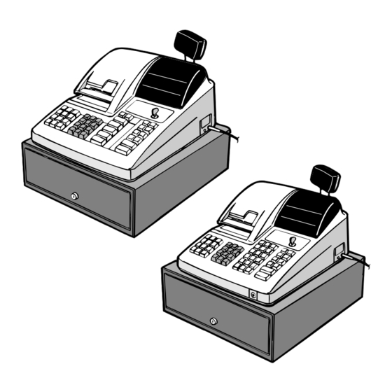
ER-A310
MODEL
ER-A330
MODEL
SRV Key : LKGIM7113RCZZ
PRINTER : ER-A310 : CR-510
:
ER-A330 : UCR-812A
(For "V" version)
This document has been published to be used
for after sales service only.
The contents are subject to change without notice.
Advertisement
Table of Contents

Related Manuals for Sharp ER-A330


Summary of Contents for Sharp ER-A330
-
Page 1: Table Of Contents
CHAPTER 11. KEY TOP KIT: ER-11KT7/12KT7/22KT7/11DK7/51DK7 (For ER-A310 & ER-A330) ....... . . 8 Parts marked with "... -
Page 2: Chapter 1. General
PARTS CODE PRICE RANK DESCRIPTIONS SRV KEY MODE KEYGRIP COVER OP key only DRIP-PROOF KEYBOARD COVER SHIELD PLATE KIT Only for ER-A330 ONE HOLE CASHIER KEY KIT DRAWER FIXING KIT 3. Supplies NAME PARTS CODE PRICE RANK DESCRIPTIONS ROLL PAPER... -
Page 3: Chapter 3. Removing The Top Cabinet (For Er-A310 & Er-A330)
CHAPTER 3. REMOVING THE TOP PWB. CABINET (For ER-A310 & ER-A330) 1. ER-A310 1) Remove the printer cover . 2) Remove the two screws . 3) Remove the screw and grounding wire . 4) Separate the top cabinet and the drawer unit. -
Page 4: Chapter 4. Removing The Bottom Cabinet (Only For Er-A330)
2) Remove the three screws . 3) Remove the screw and grounding wire . CHAPTER 4. REMOVING THE BOTTOM CABINET (Only for ER-A330) 1. ER-A330 1) Remove the top cabinet. 2) Remove the bottom cabinet from the drawer unit . -
Page 5: Chapter 5. Removing The Printer Unit (For Er-A310 & Er-A330)
CHAPTER 5. REMOVING THE PRINTER UNIT (For ER-A310 & ER-A330) 1. ER-A310 1) Remove the top cabinet. 2) Remove the printer cable from the main PWB. 3) Remove the three screws . 4) Remove the screw and grounding wire . -
Page 6: Chapter 7. Remote Drawer: Er-04Dw (For Er-A310 & Er-A330)
6) Use nippers to cut off drawer cable binding holder on the trans cover, and bind drawer cable of the ER-04DW. ER-A310 & ER-A330) Screw used in this case is an accessory of the ER-04DW. CAUTION: The drawer unit should be securely fitted to the supporting platform to avoid instability when the drawer is open. -
Page 7: Chapter 8. Drawer Fixing Kit (Dkit-8633Rczz)
7) Use nippers to cot off the drawer cable split pin of the top cabinet, 3. Installation procedure for ER-A330 and attach the top cabinet. 1) Remove the top cabinet. 2) Remove the main PWB. 3) Solder the drawer connector CN16, the resistor (1k ) R89, and the transistor (2SC3784) Q20 to the main PWB. -
Page 8: Chapter 9. Shield Plate Kit: Dkit-8666Bhzz (Only For Er-A330)
DKIT-8666BHZZ (Only 1) Turn over the drawer bottom side and remove rubber footing at two to locations. for ER-A330) 2) Fasten the bracket together with the rubber footing using the pand hand screw. Pay attention for the installing direction of the bracket that the pan 1. -
Page 9: Chapter 10. One Hole Cashier Key Kit
CHAPTER 10. ONE HOLE CLERK KEY KIT Standard provision for the TQ, TR, and TS versions of the ER- A330. 1. Component list PARTS CODE DESCRIPTION Q’ty Clerk SW body Clerk key 1 Clerk key 2 Main PWB. Clerk key 3 Clerk key 4 Clerk key 5 Clerk key 6... - Page 10 ER-12KT7, ER-22KT7 2. Installation procedure Note: There are black spacers and white spacers. Refer to the figure before for attaching them. ER-22KT7 ER-12KT7 ER-11KT7 Attach the black spacer to the left lower side, and the white spacer to the right lower side. ER-11KT7 ER-22KT7 ER-12KT7...