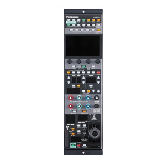
Panasonic AK-HRP1010G Operating Instructions Manual
Remote operation panel
Hide thumbs
Also See for AK-HRP1010G:
- Operating manual (29 pages) ,
- Operating instructions manual (30 pages)
Table of Contents
Advertisement
Quick Links
Advertisement
Table of Contents

Related Manuals for Panasonic AK-HRP1010G


Summary of Contents for Panasonic AK-HRP1010G
- Page 1 Operating Instructions Remote Operation Panel AK-HRP1010G Model No. Please carefully read this manual, and save this manual for future use. Before using this product, be sure to read “Read this first!” (pages 2 to 4) . ENGLISH...
-
Page 2: Read This First
Trade Name: Panasonic Model Number: AK-HRP1010G Responsible Party: Panasonic Corporation of North America Two Riverfront Plaza, Newark, NJ 07102 Support contact: 1-800-524-1448 This device complies with part 15 of the FCC Rules. Operation is subject to the following two conditions: (1) This device may not cause harmful interference, and (2) this device must accept any interference received, including interference that may cause undesired operation. - Page 3 AEEE Complies with Directive of Turkey. Note: The rating plate (serial number plate) is on the bottom of the unit. Manufactured by: Panasonic Corporation, Osaka, Japan Importer’s name and address of pursuant to EU rules: Panasonic Marketing Europe GmbH Panasonic Testing Centre...
- Page 4 4. Утилизировать в соответствии с национальным и/или местным законодательством. Правила и условия реализации не установлены изготовителем и должны соответствовать национальному и/или местному законодательству страны реализации товара. ІНФОРМАЦІЯ ПРО ПІДТВЕРДЖЕННЯ ВІДПОВІДНОСТІ ПРОДУКТУ Виробник: Panasonic Corporation Панасонік Корпорейшн Адреса виробника: Kadoma, Osaka, Japan Кадома, Осака, Японія...
-
Page 5: Table Of Contents
Table of Contents Read this first! Shutter (SHUTTER) Displaying and setting the shutter (SHUTTER) Introduction Master pedestal (M.PED) How to View This Manual Displaying and setting the master pedestal (M.PED) About trademarks and registered trademarks Iris (IRIS) About copyright Displaying and setting the iris (IRIS) Illustrations and screen displays featured in the manual Abbreviations [SELECT] dial... - Page 6 REFERENCE MAINTENANCE CAMERA/CCU MENU CONTROL ROP VOL/BUTTON IRIS LEVER SETTING ROP SETTING ROP INITIALIZE ROP VERSION SD CARD DATA SAVE SD CARD DATA LOAD SYSTEM ROP IP SETTING CAM IP SEARCH MANUAL IP SETTING CONNECT SETTING CAMERA AUTH SETTING ROP AUTH SETTING Software IP connection IP connection procedure...
-
Page 7: Introduction
For the purposes of this manual, the model numbers of the units are given as listed in the table below. Model number of unit Model number given in manual AK-HC5000G AK-HC5000 AK-HC5000GS AK-UC3300G AK-UC3300 AK-UC3300GS AK-UC4000G AK-UC4000 AK-UC4000GS AK-HRP1010G AK-HRP1010 AK-UCU500P AK-UCU500PS AK-UCU500 AK-UCU500E AK-UCU500ES AK-UCU600P AK-UCU600PS AK-UCU600 AK-UCU600E AK-UCU600ES... -
Page 8: Overview
Introduction Overview This unit is a remote operation panel for controlling a studio handy camera (AK-HC5000/AK-UC3300/AK-UC4000; sold separately) and a camera control unit (AK-UCU500/AK-UCU600; sold separately). Use a dedicated optical fiber multi cable to connect a studio handy camera to a camera control unit and use an ROP cable or IP connection to connect this unit to the camera control unit. -
Page 9: Notice
Disclaimer of warranty IN NO EVENT SHALL Panasonic Corporation BE LIABLE TO ANY PARTY OR ANY PERSON, EXCEPT FOR REPLACEMENT OR REASONABLE MAINTENANCE OF THE PRODUCT, FOR THE CASES, INCLUDING BUT NOT LIMITED TO BELOW: ANY DAMAGE AND LOSS, INCLUDING WITHOUT LIMITATION, DIRECT OR INDIRECT, SPECIAL, CONSEQUENTIAL OR EXEMPLARY, ARISING OUT OF OR RELATING TO THE PRODUCT;... -
Page 10: Restrictions On Use
4 GB to 32 GB SDXC: 64 GB For the latest information not described in the Operating Instructions, refer to the following website. https://pro-av.panasonic.net/ Observe the following points when using and storing this unit. Avoid high temperature and humidity. Avoid water droplets. -
Page 11: Features
The ROP Setup Software can be used to set the camera connections. *1: Power over Ethernet. Referred to as "PoE" in this manual. *2: For details on PoE power supply devices for which operation has been verified, consult your dealer or Panasonic representative. - 11 -... -
Page 12: Precautions For Use
Introduction Precautions for Use In addition to the safety precautions given in “Read this first!”, also observe the following instructions. Handle carefully Do not drop the unit or expose it to strong impacts or vibrations. Do not carry the unit by the [IRIS] lever. Doing so may cause a fail- ure or accident. -
Page 13: Precautions For Installation
Introduction Precautions for Installation In addition to the safety precautions given in “Read this first!”, also observe the following instructions. Be sure to ask your dealer to perform the installation and connection work for the unit. Cable connections Be sure to use dedicated ROP cables (Hirakawa Hewtech Corp. 20379-FG-SV-10 cables or equivalent). If the unit will not be used for an extended period of time, disconnect the ROP cables to save electricity. -
Page 14: Installing And Removing Rack Mount Brackets
Introduction Installing and removing rack mount brackets The unit is shipped from the factory with the rack mount brackets installed. The customer can remove the four screws that hold the rack mount brackets in place using a Phillips screwdriver. A. Rack mount bracket B. -
Page 15: Connection
Connection Connection Operation Modes Operation mode setting procedure In the factory default state, connect the CCU to the unit and then set the operation mode. Connect the CCU to the unit in the factory default state. Connect with serial Operate with IP 1. - Page 16 Connection *1: If an ROP configuration file that was saved to a memory card in IP connection is loaded in serial connection, the operation mode becomes IP connection. *2: If an ROP configuration file that was saved to a memory card in serial connection is loaded in IP connection, the operation mode becomes serial connection.
-
Page 17: System Connection Configuration
Connection System Connection Configuration The unit can be connected to a CCU via a serial connection or IP connection. Up to 99 CCUs can be controlled. Only one CCU can be connected via a serial connection. A configuration with one serial connection and 98 IP connections is possible. CCU connections Serial connection Connection example:... - Page 18 Connection IP connection Personal computer AK-UCU600 AK-UCU600 LAN cable (straight cable) PoE-compatible switching hub (100base-TX) LAN cable (straight cable) Max.100 m (328.1 ft) AK-HRP1010 *1: The CCU does not support PoE. 1. Connect the <LAN> connector on this unit to the <LAN> connector on the CCU rear panel using a LAN cable (sold separately).
-
Page 19: Parts And Their Functions
Parts and their functions Parts and their functions Front panel 1 10 11 12 13 [POWER HEAD] button Use this button to control camera power remotely. However, it will not function unless the CCU and the camera are turned on. Each press of the button turns the power of the camera on or off. - Page 20 Parts and their functions [AUTO WHITE] button Use this button to perform auto white balance adjustment. Status displays Indicates that the auto white balance adjustment has started. Flashing: Warns that the automatic white balance adjustment ended without being completed. When highlights and lowlights are lost, white balance is returned to its pre- vious value.
- Page 21 Parts and their functions [ASSIGN] button Use this button to enable or disable the menu function assigned to the button. Status displays When “FLARE”, “GAMMA”, “KNEE”, “W.CLIP”, “HD.D”, “UHD.D”, or “SD.D” are assigned to the buttons Off: When functions other than the above are assigned Off: Set the function assigned to the [ASSIGN] button in [MAINTENANCE] >...
-
Page 22: Front Panel 2
Parts and their functions Front panel 2 [ASSIGN STATUS] button Use this button to display the ASSIGN status screen. The functions assigned to the [1] to [5] (CONTROL/MODE) buttons and [ASSIGN] button are displayed on the LCD panel. When you press this button while the menu screen is displayed, the ASSIGN status screen will not appear. -
Page 23: Front Panel 3
Parts and their functions Front panel 3 LCD panel This panel displays the menu screen or status screen. [MENU] dials Use these dials to perform operations according to the menu items displayed on the LCD panel. [EXIT] button Use this button to return to the previous menu level. [UNDO] button Use this button to restore the values controlled during the setting operation to the values prior to control. -
Page 24: Front Panel 4
Parts and their functions Front panel 4 [ON] indicator (SCENE FILE) This indicator is lit when a scene file is selected. Status displays A scene file is selected. Off: A scene file is not selected. Scene file page switching but- Use this button to switch between scene file pages 1 to 5 and 6 to 8. -
Page 25: Front Panel 5
Parts and their functions Front panel 5 [ND] indicator This indicator indicates the ND filter setting status. Status displays Lit (green): Standard position set in the ROP menu. Lit (orange): Updated from the standard position set in the ROP menu. The standard position of the ND filter can be set in [MAINTENANCE] >... - Page 26 Parts and their functions [ECC] button When this button is lit, [PAINT] > [ECC] > [COLOR TEMP SW] in the ROP menu can be enabled or disabled. “Color temperature (ECC)” (see page 41) Status displays ECC operation ([COLOR TEMP SW] enabled) Off: CC filter operation ([COLOR TEMP SW] disabled) [M.GAIN] indicator...
-
Page 27: Front Panel 6
Parts and their functions Front panel 6 [SHUTTER] display The display shows the shutter value. [ON] button (SHUTTER) Turns the shutter on or off. Status displays Off: [SYNC] button (SHUTTER) Use this button switch between the shutter and sync shutter. Status displays Sync shutter Off:... -
Page 28: Front Panel 7
Parts and their functions Front panel 7 8 10 11 9 [GAIN R], [GAIN G], and [GAIN Use these control dials to adjust the white balance (R, G, B). Turning a dial changes the gain control value in the status screen. B] dials The setting values can be viewed in the [GAIN] area of the LCD panel (status screen). - Page 29 Parts and their functions [CAM SEL] indicator This indicator is lit in camera selection mode. Status displays Camera selection mode Off: Camera selection mode canceled [SELECT] dial Use this dial to select and adjust any of [TEMP], [CAM SEL], [SYNC], [USER], and [MFLR]. The setting values can be viewed in the [TEMP] area of the LCD panel (status screen).
-
Page 30: Front Panel 8
Parts and their functions Front panel 8 [EXT] indicator This indicator lights to warn that the lens extender is set to something other than 1x. Status displays The lens extender is set to something other than 1x. Off: This indicates that the lens extender is not being used or that it is not available. [D.EXT] indicator This indicator lights to warn that the digital extender is set to something other than 1x. - Page 31 Parts and their functions [COARSE] dial Adjusts how much the iris is opened or closed when the [IRIS] lever is moved. Dial operation This is enabled only when [MAINTENANCE] > [IRIS LEVER SETTING] > [LEVER MODE] is set to “ABS”. Turn right (clockwise) (OPEN): The [IRIS] lever will operate at its most sensitive range.
- Page 32 Parts and their functions [M.PED LOCK] button Use this button to disable (lock) master pedestal operation. Lock range Status displays Off: Master pedestal can be controlled. Lit: Operation is disabled (locked). When the [M.PED] dial is returned to the lock position, the button turns off and normal control becomes possible.
-
Page 33: Front Panel 9
Parts and their functions Front panel 9 Camera number/tally display This display shows the camera number information and tally information. [ALM] indicator This is the camera and CCU warning indicator lamp. Consult your dealer if a failure occurs. The indicator lights to indicate when the camera and CCU optical reception level is not strong enough, when a data error has occurred in the CCU optical transmission/reception section, or when a fan error or temperature error has occurred on the camera or CCU. - Page 34 Parts and their functions Memory card slot Insert a memory card into this slot. You can save the settings of the unit and the scene files, user files, and other files to a memory card. “Memory cards” (see page 10) Memory card access indicator This indicator lights when data is read from or written to a memory card.
-
Page 35: Connectors
Parts and their functions Connectors <CCU> connector This connector is for serial connections to the CCU. <LAN> connector Use a LAN cable to connect to a CCU or personal computer that supports IP connections. <PREVIEW> connector This connector outputs preview signals. <SIGNAL GND>... -
Page 36: Adjustment And Settings
Adjustment and settings Adjustment and settings Auto Setup Starting auto setup Before starting auto setup Choose [FUNCTION] > [SYSTEM CAM INFO] > [ASU MODE] in the ROP menu to select “FULL” or “EASY” mode. “ASU MODE” (see page 103) FULL Standard setup based on an outdoor shooting chart EASY Easy setup based on an outdoor shooting chart... -
Page 37: Scene File
Adjustment and settings Scene file Storing and opening scene files Storing scene files You can register the data currently being operated as a scene file. A. [STORE] button B. [1/6], [2/7], [3/8], [4], and [5] buttons C. Scene file page switching button Operating procedure 1. -
Page 38: Paint Lock
Adjustment and settings PAINT LOCK Using the PAINT LOCK Lock (disable) the paint control operations. The following operations are targets of the paint control lock (PAINT LOCK). [GAIN R], [GAIN G], and [GAIN B] dials (B): White balance adjustment [BLACK R], [BLACK G], and [BLACK B] (C) dials: Pedestal or flare adjustment [DTL] dial (D): Detail enhancer adjustment A. -
Page 39: Nd Filter
Adjustment and settings ND filter Displaying and setting the ND filter The adjustment value of the ND filter is displayed on the [ND] display (B). When the setting value is changed from the standard position set in the ROP menu, the [ND] indicator (A) is orange lit. (The standard pos- ition remains set while the indicator is green lit.) “STD POSI ND”... -
Page 40: Cc Filter
Adjustment and settings CC filter Displaying and setting the CC filter The adjustment value of the CC filter is displayed on the [CC] display (B). When the setting value is changed from the standard position set in the ROP menu, the [CC] indicator (A) is orange lit. (The standard pos- ition remains set while the indicator is green lit.) “STD POSI CC”... -
Page 41: Color Temperature (Ecc)
Adjustment and settings Color temperature (ECC) Setting the color temperature (ECC) When the [ECC] button (A) is lit, you can select and change the preset color temperature. You can verify the adjustment value on the status screen. “ECC” (see page 51) A. -
Page 42: Master Gain (M.gain)
Adjustment and settings Master gain (M.GAIN) Displaying and setting the master gain (M.GAIN) The adjustment value of the master gain (M.GAIN) is displayed on the [M.GAIN] display (B). When the setting value is changed from the standard position set in the ROP menu, the [M.GAIN] indicator (A) is orange lit. (The standard position remains set while the indicator is green lit.) “STD POSI M. -
Page 43: Shutter (Shutter)
Adjustment and settings Shutter (SHUTTER) Displaying and setting the shutter (SHUTTER) You can turn the shutter on or off by pressing the [ON] button (SHUTTER) (A). (The shutter is turned on when the button is lit.) The shutter value is displayed in the [SHUTTER] display (B) and can be adjusted using the [SHUTTER] setting buttons (C). Step shutter adjustment is enabled when the [SYNC] button (SHUTTER) (D) is not lit, and sync shutter adjustment is enabled when the but- ton is lit. -
Page 44: Master Pedestal (M.ped)
Adjustment and settings Master pedestal (M.PED) Displaying and setting the master pedestal (M.PED) The master pedestal (M.PED) setting is displayed on the [M.PED] display (A) when the [M.PED] dial (B) is operated. Adjustment is possible while the [M.PED LOCK] button (C) is off (canceled). A. -
Page 45: Iris (Iris)
Adjustment and settings Iris (IRIS) Displaying and setting the iris (IRIS) Manual adjustment When the auto iris is not on, the iris can be adjusted manually. The iris value is displayed on the [IRIS] display (A). Adjustment is possible while the [AUTO] button (C) is off (AUTO is canceled). Adjustment is possible while the [IRIS LOCK] button (D) is off (iris lock is canceled). - Page 46 Adjustment and settings A. [AUTO] button B. [IRIS] lever Operating procedure 1. Press the [AUTO] button (A) to turn on the button. The auto iris turns on. When the auto iris is on, the convergence level of the iris can be adjusted with the [IRIS] lever (B). Moving it forward adjusts the level in the CLOSE direction and moving it backward adjusts the level in the OPEN direction.
-
Page 47: [Select] Dial
Adjustment and settings [SELECT] dial Using the select dial Use the [SELECT] dial (A) to select and adjust the function of any of [TEMP], [CAM SEL], [SYNC], [USER], and [MFLR]. Indicator Function The value of [COLOR TEMP] can be changed with the dial. TEMP “COLOR TEMP”... -
Page 48: Camera Selection
Adjustment and settings Camera selection Select the camera to be the target for control with the unit. Select the camera after switching to camera selection mode. A. [SELECT] dial B. [CAM SEL] indicator Operating procedure 1. Press the [SELECT] dial (A) for at least approximately 1 second. This allows you to select [TEMP], [CAM SEL], [SYNC], [USER], and [MFLR]. -
Page 49: Status Screen
Status screen Status screen Displaying and operating the status screen The status screen is displayed on the LCD panel of the unit when the ROP menu (REMOTE OPERATION MENU) is not being used (i.e., the menu is turned OFF). G A I N G A M M A K N E E H D . -
Page 50: Items Displayed On The Status Screen
Status screen Items displayed on the status screen OPT LEVEL This displays the optical transmission strength. G A I N G A M M A K N E E H D . D M A T R I X C A M R C V : C C U R C V : G A I N U H D D T L... -
Page 51: Scene
Status screen SCENE This displays the scene setting information. G A I N G A M M A K N E E H D . D M A T R I X S C E N E E C C S H T 1 5 0 0 0 K 1 / 1 0 0... -
Page 52: Assign Status Screen
Status screen ASSIGN status screen The items assigned to the [1] to [5] buttons (B), [ASSIGN] button, and [USER] indicator and the SETTING number loaded in [MAINTENANCE] > [ROP SETTING] > [SETTING LOAD] can be checked on the LCD panel. Press the [ASSIGN STATUS] button (A) to display the assignments. -
Page 53: Rop Menu
ROP menu ROP menu Displaying menus The LCD panel of the unit can be used to operate the ROP menu (REMOTE OPERATION MENU). ROP menu operation is a function that is enabled when the unit is connected to a camera or CCU. Follow the procedure below to display the ROP menu. -
Page 54: Basic Menu Operations
ROP menu Basic menu operations 1. Press the [MENU] button (A) The menu appears on the LCD panel (B). C 0 1 : A K - U C 4 0 0 0 1 / 5 P A I N T P A I N T S W S H U T T E R B L A C K... -
Page 55: Other Menu Operations
ROP menu 5. Turn the [MENU] dial (C) to set the items Turn the dial at the same position as each item in the screen. As long as you do not move the cursor after changing a setting, you can restore the value prior to the change with the [UNDO] but- ton (D). -
Page 56: Rop Menu List
ROP menu ROP menu list PAINT BLACK SHADING “BLACK SHADING” (see page 69) WHITE SHADING “WHITE SHADING” (see page 69) FLARE “FLARE” (see page 69) “GAMMA” (see page 69) GAMMA “BLACK GAMMA” (see page 69) BLACK GAMMA “DRS” (see page 69) “WHITE CLIP”... - Page 57 ROP menu “R GAIN” (see page 75) R GAIN G GAIN “G GAIN” (see page 75) B GAIN “B GAIN” (see page 75) RGB GAIN GAIN OFFSET “GAIN OFFSET” (see page 75) “GAIN ABS” (see page 75) GAIN ABS “G GAIN REL CONT” (see page 75) G GAIN REL CONT “R GAIN”...
- Page 58 ROP menu “R GAMMA” (see page 81) R GAMMA B GAMMA “B GAMMA” (see page 81) M.GAMMA “M.GAMMA” (see page 81) GAMMA MODE “GAMMA MODE” (see page 81) “INITIAL GAMMA” (see page 81) INITIAL GAMMA “BLACK STRCH LV” (see page 81) BLACK STRCH LV GAMMA “DYNAMIC LEVEL”...
- Page 59 ROP menu “M.DTL” (see page 87) M.DTL H DTL LEVEL “H DTL LEVEL” (see page 87) V DTL LEVEL “V DTL LEVEL” (see page 87) PEAK FRQ “PEAK FRQ” (see page 87) “V DTL FRQ” (see page 87) V DTL FRQ “CRISP”...
- Page 60 ROP menu “MEMORY SELECT” (see page 90) MEMORY SELECT CURSOR “CURSOR” (see page 90) H POS “H POS” (see page 90) V POS “V POS” (see page 90) “SKIN GET” (see page 90) SKIN GET “ZEBRA SW” (see page 90) ZEBRA SW “ZEBRA EFFECT”...
- Page 61 ROP menu “PRESET MATRIX” (see page 92) PRESET MATRIX LINEAR TABLE “LINEAR TABLE” (see page 92) COLOR CORRECT “COLOR CORRECT” (see page 92) CURSOR “CURSOR” (see page 92) “H POS” (see page 92) H POS “V POS” (see page 92) V POS “GET”...
- Page 62 ROP menu “R HLG B.GAMMA” (see page 96) R HLG B.GAMMA B HLG B.GAMMA “B HLG B.GAMMA” (see page 96) M.HLG B.GAMMA “M.HLG B.GAMMA” (see page 96) HLG KNEE POINT “HLG KNEE POINT” (see page 96) “HLG KNEE SLOPE” (see page 96) HLG KNEE SLOPE “HLG B.GAMMA”...
- Page 63 ROP menu “COLOR CORRECT” (see page 100) COLOR CORRECT “SAT” (see page 100) PHASE “PHASE” (see page 100) SAT R “SAT R” (see page 100) “PHASE R” (see page 100) PHASE R “SAT R-R-Mg” (see page 100) SAT R-R-Mg “PHASE R-R-Mg” (see page 100) PHASE R-R-Mg “SAT R-Mg”...
- Page 64 ROP menu “SAT G-Yl-Yl” (see page 100) SAT G-Yl-Yl PHASE G-Yl-Yl “PHASE G-Yl-Yl” (see page 100) SAT Yl “SAT Yl” (see page 100) PHASE Yl “PHASE Yl” (see page 100) “SAT Yl-Yl-R” (see page 100) SAT Yl-Yl-R “PHASE Yl-Yl-R” (see page 100) COLOR ADJUSTMENT PHASE Yl-Yl-R “SAT Yl-R”...
- Page 65 ROP menu “FORMAT MODE(push)” (see page 104) FORMAT MODE(push) FORMAT “FORMAT” (see page 104) CAMERA NUM “CAMERA NUM” (see page 104) D/C MODE “D/C MODE” (see page 104) “U/C MODE” (see page 104) U/C MODE “RETURN FS” (see page 104) RETURN FS “RETURN1 SELECT”...
- Page 66 ROP menu “MODE” (see page 109) MODE FILE No. “FILE No.” (see page 109) LENS FILE SW “LENS FILE SW” (see page 109) FILE NAME “FILE NAME” (see page 110) “EXECUTE” (see page 110) EXECUTE “EXTENDER” (see page 110) EXTENDER “FILE NUM”...
- Page 67 ROP menu “CONTROL1” (see page 114) CONTROL1 CONTROL2 “CONTROL2” (see page 114) CONTROL3 “CONTROL3” (see page 114) CONTROL4 “CONTROL4” (see page 114) “CONTROL5” (see page 114) CONTROL5 “MODE1” (see page 115) MODE1 “MODE2” (see page 115) MODE2 “MODE3” (see page 115) MODE3 MODE4 “MODE4”...
- Page 68 ROP menu “ROP DATA” (see page 121) ROP DATA SETTING DATA “SETTING DATA” (see page 121) CONNECT DATA “CONNECT DATA” (see page 121) CAM ALL DATA “CAM ALL DATA” (see page 121) “REF.FILE” (see page 121) SD CARD DATA SAVE REF.FILE “USER FILE”...
-
Page 69: Paint
ROP menu PAINT PAINT SW The setting values will vary also depending on the connected camera. Items with the function disabled are indicated by “-”. For details on each setting item, check also the operating instructions of the camera and CCU to be connected. C 0 1 : A K - U C 4 0 0 0 1 / 2 P A I N T S W... -
Page 70: Shutter
ROP menu SHUTTER The setting values will vary also depending on the connected camera. Items with the function disabled are indicated by “-”. For details on each setting item, check also the operating instructions of the camera and CCU to be connected. C 0 1 : A K - U C 4 0 0 0 1 / 1 S H U T T E R... -
Page 71: Black Shading
ROP menu BLACK SHADING The setting values will vary also depending on the connected camera. Items with the function disabled are indicated by “-”. For details on each setting item, check also the operating instructions of the camera and CCU to be connected. C 0 1 : A K - U C 4 0 0 0 1 / 2 B L A C K S H A D I N G... -
Page 72: Pedestal
ROP menu PEDESTAL The setting values will vary also depending on the connected camera. Items with the function disabled are indicated by “-”. For details on each setting item, check also the operating instructions of the camera and CCU to be connected. C 0 1 : A K - U C 4 0 0 0 1 / 1 P E D E S T A L... -
Page 73: Uhd Chroma
ROP menu UHD CHROMA The control destination differs depending on the unit configuration. When the camera is an AK-UC4000 or AK-UC3300 The control is performed for the camera. When the camera is other than the above The control is performed for the CCU. The setting values will vary also depending on the connected camera. -
Page 74: Hd Chroma
ROP menu HD CHROMA The control destination differs depending on the unit configuration. When the camera is an AK-UC4000 or AK-UC3300 The control is performed for the camera. When the camera is other than the above When the system format is set to UHD, the control is performed for the CCU. Otherwise, the control is performed for the camera. The setting values will vary also depending on the connected camera. -
Page 75: Rgb Gain
ROP menu RGB GAIN The setting values will vary also depending on the connected camera. Items with the function disabled are indicated by “-”. For details on each setting item, check also the operating instructions of the camera and CCU to be connected. C 0 1 : A K - U C 4 0 0 0 1 / 1 R G B G A I N... -
Page 76: Color Temp
ROP menu COLOR TEMP The setting values will vary also depending on the connected camera. Items with the function disabled are indicated by “-”. For details on each setting item, check also the operating instructions of the camera and CCU to be connected. C 0 1 : A K - U C 4 0 0 0 1 / 1 C O L O R T E M P... -
Page 77: Ecc
ROP menu The setting values will vary also depending on the connected camera. Items with the function disabled are indicated by “-”. For details on each setting item, check also the operating instructions of the camera and CCU to be connected. C 0 1 : A K - U C 4 0 0 0 1 / 1 E C C... -
Page 78: Cam User Sw Temp
ROP menu CAM USER SW TEMP The setting values will vary also depending on the connected camera. Items with the function disabled are indicated by “-”. For details on each setting item, check also the operating instructions of the camera and CCU to be connected. C 0 1 : A K - U C 4 0 0 0 1 / 1 C A M U S E R S W T E M P... -
Page 79: White Shading
ROP menu WHITE SHADING The setting values will vary also depending on the connected camera. Items with the function disabled are indicated by “-”. For details on each setting item, check also the operating instructions of the camera and CCU to be connected. C 0 1 : A K - U C 4 0 0 0 1 / 2 W H I T E S H A D I N G... -
Page 80: Flare
ROP menu FLARE The setting values will vary also depending on the connected camera. Items with the function disabled are indicated by “-”. For details on each setting item, check also the operating instructions of the camera and CCU to be connected. C 0 1 : A K - U C 4 0 0 0 1 / 1 F L A R E... -
Page 81: Gamma
ROP menu GAMMA The setting values will vary also depending on the connected camera. Items with the function disabled are indicated by “-”. For details on each setting item, check also the operating instructions of the camera and CCU to be connected. C 0 1 : A K - U C 4 0 0 0 1 / 2 G A M M A... -
Page 82: Black Gamma
ROP menu BLACK GAMMA The setting values will vary also depending on the connected camera. Items with the function disabled are indicated by “-”. For details on each setting item, check also the operating instructions of the camera and CCU to be connected. C 0 1 : A K - U C 4 0 0 0 1 / 1 B L A C K G A M M A... -
Page 83: Knee
ROP menu KNEE The setting values will vary also depending on the connected camera. Items with the function disabled are indicated by “-”. For details on each setting item, check also the operating instructions of the camera and CCU to be connected. C 0 1 : A K - U C 4 0 0 0 1 / 1 K N E E... -
Page 84: White Clip
ROP menu WHITE CLIP The setting values will vary also depending on the connected camera. Items with the function disabled are indicated by “-”. For details on each setting item, check also the operating instructions of the camera and CCU to be connected. C 0 1 : A K - U C 4 0 0 0 1 / 1 W H I T E C L I P... -
Page 85: Drs
ROP menu The setting values will vary also depending on the connected camera. Items with the function disabled are indicated by “-”. For details on each setting item, check also the operating instructions of the camera and CCU to be connected. C 0 1 : A K - U C 4 0 0 0 1 / 1 D R S... -
Page 86: Uhd Dtl
ROP menu UHD DTL The control destination differs depending on the unit configuration. When the camera is an AK-UC4000 or AK-UC3300 The control is performed for the camera. When the camera is other than the above The control is performed for the CCU. The setting values will vary also depending on the connected camera. -
Page 87: Hd Dtl
ROP menu HD DTL The control destination differs depending on the unit configuration. When the camera is an AK-UC4000 or AK-UC3300 The control is performed for the camera. When the camera is other than the above When the system format is set to UHD, the control is performed for the CCU. Otherwise, the control is performed for the camera. The setting values will vary also depending on the connected camera. -
Page 88: Sd Dtl
ROP menu SD DTL The control destination differs depending on the unit configuration. When the camera is an AK-UC4000 or AK-UC3300 The fixed value is displayed. The setting cannot be changed. When the camera is other than the above The control is performed for the CCU. Otherwise, the control is performed for the camera. The setting values will vary also depending on the connected camera. -
Page 89: Uhd Skin Tone Dtl
ROP menu UHD SKIN TONE DTL The control destination differs depending on the unit configuration. When the camera is an AK-UC4000 or AK-UC3300 The control is performed for the camera. When the camera is other than the above The control is performed for the CCU. The setting values will vary also depending on the connected camera. -
Page 90: Hd Skin Tone Dtl
ROP menu HD SKIN TONE DTL The control destination differs depending on the unit configuration. When the camera is an AK-UC4000 AK-UC3300 The control is performed for the camera. When the camera is other than the above When the system format is set to UHD, the control is performed for the CCU. Otherwise, the control is performed for the camera. The setting values will vary also depending on the connected camera. -
Page 91: Linear Matrix
ROP menu LINEAR MATRIX The setting values will vary also depending on the connected camera. Items with the function disabled are indicated by “-”. For details on each setting item, check also the operating instructions of the camera and CCU to be connected. C 0 1 : A K - U C 4 0 0 0 1 / 2 L I N E A R M A T R I X... -
Page 92: Color Correction
ROP menu COLOR CORRECTION The setting values will vary also depending on the connected camera. Items with the function disabled are indicated by “-”. For details on each setting item, check also the operating instructions of the camera and CCU to be connected. C 0 1 : A K - U C 4 0 0 0 1 / 4 C O L O R C O R R E C T I O N... - Page 93 ROP menu Item Setting details COLOR CORRECT Selects the color component in 12-axis matrix memory to adjust. Adjusts the saturation of the color component selected in [COLOR CORRECT]. PHASE Adjusts the color phase of the color component selected in [COLOR CORRECT]. SAT G Adjusts the color saturation of green.
-
Page 94: Skin Correction
ROP menu SKIN CORRECTION The setting values will vary also depending on the connected camera. Items with the function disabled are indicated by “-”. For details on each setting item, check also the operating instructions of the camera and CCU to be connected. C 0 1 : A K - U C 4 0 0 0 1 / 1 S K I N C O R R E C T I O N... -
Page 95: Dnr
ROP menu The setting values will vary also depending on the connected camera. Items with the function disabled are indicated by “-”. For details on each setting item, check also the operating instructions of the camera and CCU to be connected. C 0 1 : A K - U C 4 0 0 0 1 / 1 D N R... -
Page 96: Hdr-Paint
ROP menu HDR-PAINT The setting values will vary also depending on the connected camera. Items with the function disabled are indicated by “-”. For details on each setting item, check also the operating instructions of the camera and CCU to be connected. C 0 1 : A K - U C 4 0 0 0 1 / 3 H D R - P A I N T... - Page 97 ROP menu Item Setting details SDR CONV SLOPE Sets the SDR slope. - 97 -...
-
Page 98: Non Linear Matrix
ROP menu NON LINEAR MATRIX The setting values will vary also depending on the connected camera. Items with the function disabled are indicated by “-”. For details on each setting item, check also the operating instructions of the camera and CCU to be connected. C 0 1 : A K - U C 4 0 0 0 1 / 2 N O N L I N E A R M A T R I X... -
Page 99: Color Adjustment
ROP menu COLOR ADJUSTMENT The setting values will vary also depending on the connected camera. Items with the function disabled are indicated by “-”. For details on each setting item, check also the operating instructions of the camera and CCU to be connected. C 0 1 : A K - U C 4 0 0 0 1 / 5 C O L O R A D J U S T M E N T... - Page 100 ROP menu Item Setting details COLOR CORRECT Selects the color component in 12-axis matrix memory to adjust. Adjusts the saturation of the color component selected in [COLOR CORRECT]. PHASE Adjusts the color phase of the color component selected in [COLOR CORRECT]. SAT R Adjusts the color saturation of red.
- Page 101 ROP menu Item Setting details SAT Yl-R Adjusts the color saturation between yellow and red. PHASE Yl-R Adjusts the color phase between yellow and red. SAT Yl-R-R Adjusts the color saturation between “color between yellow and red” and red. PHASE Yl-R-R Adjusts the color phase between “color between yellow and red”...
-
Page 102: Function
ROP menu FUNCTION SYSTEM CAM INFO The setting values will vary also depending on the connected camera. Items with the function disabled are indicated by “-”. For details on each setting item, check also the operating instructions of the camera and CCU to be connected. C 0 1 : A K - U C 4 0 0 0 1 / 3 S Y S T E M C A M I N F O... - Page 103 ROP menu Item Setting details TALLY GUARD When set to ON, this function disables automatic ASU, AWB, ABB operation while the tally is ASU FILTER Sets the operation of the ND/CC filter when auto setup is started. The filter stored in the reference file is used when operation starts. CURRENT Auto setup starts at the filter position made prior to startup.
-
Page 104: System Ccu Info
ROP menu SYSTEM CCU INFO The setting values will vary also depending on the connected camera. Items with the function disabled are indicated by “-”. For details on each setting item, check also the operating instructions of the camera and CCU to be connected. C 0 1 : A K - U C 4 0 0 0 1 / 3 S Y S T E M C C U I N F O... - Page 105 ROP menu Item Setting details HD H FINE Make the fine setting of the H_FINE phase used with GL HD REF. SD H COARSE Make the coarse setting of the H_FINE phase used with GL SD REF. SD H FINE Make the fine setting of the H_FINE phase used with GL SD REF.
-
Page 106: Auto Iris Setting
ROP menu AUTO IRIS SETTING The setting values will vary also depending on the connected camera. Items with the function disabled are indicated by “-”. For details on each setting item, check also the operating instructions of the camera and CCU to be connected. C 0 1 : A K - U C 4 0 0 0 1 / 1 A U T O I R I S S E T T I N G... -
Page 107: Lens Control
ROP menu LENS CONTROL This is enabled for a camera or other device that supports lens operation from a remote control. C 0 1 : A K - U C 4 0 0 0 L E N S C O N T R O L 1 / 1 FOCUS ZOOM... -
Page 108: Shutter Select
ROP menu SHUTTER SELECT The setting values will vary also depending on the connected camera. Items with the function disabled are indicated by “-”. For details on each setting item, check also the operating instructions of the camera and CCU to be connected. C 0 1 : A K - U C 4 0 0 0 1 / 1 S H U T T E R S E L E C T... -
Page 109: Lens File Edit
ROP menu LENS FILE EDIT The setting values will vary also depending on the connected camera. Items with the function disabled are indicated by “-”. For details on each setting item, check also the operating instructions of the camera and CCU to be connected. C 0 1 : A K - U C 4 0 0 0 1 / 4 L E N S F I L E E D I T... - Page 110 ROP menu Item Setting details FILE NAME Displays the file name of the file number specified in [FILE No.]. The file name can be changed when [MODE] is set to “STORE”. If you press one of the [MENU] dials, the screen transitions to the keyboard input screen to perform the oper- ation to change the file name.
-
Page 111: Monitor
ROP menu MONITOR The setting values will vary also depending on the connected camera. Items with the function disabled are indicated by “-”. For details on each setting item, check also the operating instructions of the camera and CCU to be connected. C 0 1 : A K - U C 4 0 0 0 1 / 1 M O N I T O R... -
Page 112: Reference
ROP menu REFERENCE C 0 1 : A K - U C 4 0 0 0 R E F E R E N C E 1 / 1 REF.CALL STORE STORE (push) EXEC FCTRY USER1 (push) Item Setting value Setting details REF.CALL(push) FCTRY Recalls the reference setting information (factory file, user file, and reference file). -
Page 113: Maintenance
ROP menu MAINTENANCE CAMERA/CCU MENU CONTROL This menu can be operated when the setting value for the CCU picture monitor (PM) is 720p. C 0 1 : A K - U C 4 0 0 0 1 / 1 C A M E R A / C C U M E N U C O N T R O L CAM MENU CAM MENU CAM MENU... -
Page 114: Rop Vol/Button
ROP menu ROP VOL/BUTTON C 0 1 : A K - U C 4 0 0 0 R O P V O L / B U T T O N 1 / 2 CONTROL CONTROL CONTROL CONTROL GAIN GAMMA KNEE UHD.D CONTROL MODE... - Page 115 ROP menu Item Setting value Setting details MODE1 GAMMA Sets the functions to assign to buttons [1] to [5] (CONTROL/MODE). FLARE The setting values represent the following functions. KNEE GAMMA: GAMMA W.CLIP FLARE: FLARE U.CHRM KNEE: KNEE H.CHRM W.CLIP: WHITE CLIP MODE2 H.COL U.CHRM: UHD CHROMA...
- Page 116 ROP menu Item Setting value Setting details SKIN DTL SW Selects the target of skin tone detail control operations on the panel. UHD: Control UHD skin tone detail. HD: Control HD skin tone detail. B. GAMMA SW SDR: This is the switch of the BLACK GAMMA menu. HDR: Controls ON/OFF of B.GAMMA in HDR-PAINT.
-
Page 117: Iris Lever Setting
ROP menu IRIS LEVER SETTING C 0 1 : A K - U C 4 0 0 0 I R I S L E V E R S E T T I N G 1 / 1 LEVER RELATIVE MODE PRIORITY MODE BOTH... -
Page 118: Rop Setting
ROP menu ROP SETTING C 0 1 : A K - U C 4 0 0 0 R O P S E T T I N G 1 / 1 7SEG-1 7SEG-2 BRIGHT BRIGHT BRIGHT BRIGHT CALL CALL BUZZER PERIOD CYCLE SETTING SETTING... -
Page 119: Rop Initialize
ROP menu ROP INITIALIZE C 0 1 : A K - U C 4 0 0 0 R O P I N I T I A L I Z E 1 / 1 ROP/IRIS ITEM Item Setting details This is all setting items including network connection settings controlled by the ROP. However, it does not apply to IRIS calibration information. -
Page 120: Rop Version
ROP menu ROP VERSION C 0 1 : A K - U C 4 0 0 0 R O P V E R S I O N 1 / 1 UPGRADE SYSTEM VERSION 1.00-00-0.00 SOFT VERSION FPGA VERSION 1.00-00-0.00 1.00-00-0.00 Item Setting value Setting details... -
Page 121: Sd Card Data Save
ROP menu SD CARD DATA SAVE C 0 1 : A K - U C 4 0 0 0 S D C A R D D A T A S A V E 1 / 1 SETTING CONNECT DATA DATA DATA CAM ALL REF. -
Page 122: Sd Card Data Load
ROP menu SD CARD DATA LOAD C 0 1 : A K - U C 4 0 0 0 S D C A R D D A T A L O A D 1 / 1 FILE SELECT ROP_DAT GET FILE(push) FILE EXECUTE If you operate GET FILE, a list of corresponding data saved in the SD card is displayed. - Page 123 ROP menu Item Setting value Setting details PUT FILE SET.1? to SET.5? Specify the LOAD destination type. REF.1 to REF.3 This cannot be selected when FILE SELECT is set to “ROP_DATA”, “SET USER1 to USER3 ALL”, “SNNCT”, “CAM ALL”, “ALL SCN”, “ALL USER”, “ALL REF”, or “ALL SCENE1 to SCENE8 LENS”.
-
Page 124: System
ROP menu SYSTEM ROP IP SETTING C 0 1 : A K - U C 4 0 0 0 1 / 2 R O P I P S E T T I N G NETWORK SETTING STATIC PORT SAVE 35200 (push) C 0 1 : A K - U C 4 0 0 0 2 / 2... - Page 125 ROP menu Item Setting details SUBNET Sets the subnet mask of the unit. The values that can be set for each octet are as follows. 1st octet: 0 to 255 2nd octet: 0 to 255 3rd octet: 0 to 255 4th octet: 0 to 255 In addition, the setting values will be checked when confirmed (written to flash memory), and an error mes- sage will appear and setting will not be possible when the subnet mask is as follows.
-
Page 126: Cam Ip Search
ROP menu CAM IP SEARCH The setting values will vary depending on the connected camera. C 0 1 : A K - U C 4 0 0 0 C A M I P S E A R C H 1 / 34 CAM IP SEARCH SAVE... -
Page 127: Manual Ip Setting
ROP menu MANUAL IP SETTING C 0 1 : A K - U C 4 0 0 0 M A N U A L I P S E T T I N G 1 / 1 CAM No. SELECT CAM1 CAM IP PORT SAVE... -
Page 128: Connect Setting
ROP menu CONNECT SETTING C 0 1 : A K - U C 4 0 0 0 C O N N E C T S E T T I N G 1 / 9 CAM No. CONNECT SELECT MODE CAM1 Serial CAM1 CAM2... -
Page 129: Camera Auth Setting
ROP menu CAMERA AUTH SETTING Set the user name and password for authenticating connections to the camera with the specified camera control number. Set the user name and password that are set on the camera. C 0 1 : A K - U C 4 0 0 0 1 / 1 C A M E R A A U T H S E T T I N G CAM No. -
Page 130: Rop Auth Setting
ROP menu ROP AUTH SETTING Register the account for access to the ROP. This is not set in the initial state. It will be cleared by ALL of INITIALIZE. When it is not set, [NEW ID] and [NEW PASSWORD] will be displayed in red. C 0 1 : A K - U C 4 0 0 0 1 / 1 R O P A U T H S E T T I N G... -
Page 131: Software
This section describes how to install ROP Setup Software. You can obtain the software from the support desk on the following website. https://pro-av.panasonic.net/ 1. Download the zip file for ROP Setup Software from the support desk on the website. 2. Double-click the downloaded zip file and extract the software. -
Page 132: Connecting And Setting The Personal Computer
Software Connecting and setting the personal computer Establish an IP connection for the personal computer on which ROP Setup Software is installed. Configure the network settings of the personal computer. Configure the network settings of the personal computer so that the same segment of the devices being connected is used. The recommended settings are shown below. -
Page 133: Rop Setup Software
Software ROP Setup Software ROP Setup Software is software to configure the settings for connecting the unit and a CCU from a personal computer. It allows you to con- figure the settings while checking each item in a list. First, use [NETWORK SEARCH] to search for the ROPs and cameras connected to the same network. The search results will be displayed in [ROP List] and [CAMERA List]. -
Page 134: Notice About Using Rop Setup Software
Software [SAVE] button Stores the information set in CONNECT SETTING List on external media. Follow the instructions on the save screen to store the information. [LOAD] button Loads saved data and displays it in CONNECT SETTING List. When you click the [LOAD] button, the load screen appears. -
Page 135: Reference
Reference Reference Connector pin assignment table 1 <CCU> connector (Hirose Electric: HR10A-10R-10P (71)) Pin No. Function Polarity Flow of signal CAM DATA (H) CAM→ROP CAM DATA (L) CAM→ROP CAM CONT (H) ROP→CAM CAM CONT (L) ROP→CAM 12 V 2 <LAN> connector Complies with 100base-TX. -
Page 136:
Reference 3 <PREVIEW> connector (JST: JEY-9S-1A3F(LF)) Pins 1 and 2 are connectors for outputting the preview signal. Contact output is provided while the [IRIS] lever or [PREVIEW] button is pressed. This is a dry contact. Pin No. Function Flow of signal Remarks P.VIEW COM ROP→external control...Connector -
Page 137: Appearance
Reference Appearance Unit: mm (inch) 102(4) 66(2-5/8) 55(2-3/16) (1-1/4) 113(4-7/16) - 137 -... -
Page 138: Specifications
Specifications Specifications General 12 V DC ( ) (Power supply from camera/CCU: 10 V - 16 V DC) Power supply 42 V - 57 V DC ( ) (PoE power supply) 0.9 A (Power supply from camera/CCU: 10 V - 16 V DC) Current consumption 0.3 A (PoE power supply) indicates safety information. -
Page 139: Index
Index Index 1 to 9 (Numeric) CONTROL/MODE button 1/6, 2/7, 3/8, 4, and 5 buttons (SCENE FILE) D.EXT indicator ALM indicator ASSIGN ASSIGN button DRS button ASSIGN STATUS button DTL dial ASSIGN status screen AUTO BLACK button AUTO button ECC button AUTO IRIS SETTING EXIT button AUTO SET UP button... - Page 140 Index REF. RECALL button M.GAIN REFERENCE M.GAIN display RELATIVE button M.GAIN indicator RGB GAIN M.GAIN setting buttons ROP AUTH SETTING M.PED ROP INITIALIZE M.PED dial ROP IP SETTING M.PED display ROP menu M.PED LOCK button ROP SETTING MANUAL IP SETTING ROP Setup Software Master gain ROP VERSION...
- Page 141 Index VAR button WHITE CLIP WHITE SHADING - 141 -...
- Page 142 Web Site: http://www.panasonic.com © Panasonic Corporation 2021...