
Related Manuals for Kenwood CS-1022


Summary of Contents for Kenwood CS-1022
- Page 1 CS-1022.CS-1021 ,CS-1012 (DUAL TRACE OSCILLOSCOPE) CS-1020, CS-101 • (SINGLE TRACE OSCILLOSCOPE) INSTRUCTION MANUAL...
-
Page 2: Table Of Contents
SAFETY Symbol in This Manual Use the Proper Power Cord This symbol indicates where applicable cautionary or Use only the power cord and connector specified for your other information is t o be found. product. Power Source Use the Proper Fuse This equipment operates from a power source that does To avoid fire hazard, use a fuse of the correct type. -
Page 3: Features
• Time base permits the high sweep speed. • CS-1022 and 1 0 1 2 are provided w i t h CH1 OUTPUT C S - 1 0 2 2 , 1 0 2 0 ; 20nsec/div ( x 10 MAG) terminal to monitor input signal of C H 1 . -
Page 4: Specifications
SPECIFICATIONS CS-1022 CS-1021 CS-1012 CS-1020 CS-1010 150FTM31 150GTM31A 150GTM31A 150FTM31 150GTM31A or 150UTM31 Acceleration Voltage 6 kV 2 kV 2 kV 6 kV 2 kV 8 x 1 0 div (1 div= 10 mm) Display Area Type Rectangular, with internal graticule... - Page 5 CS-1022 CS-1021 0S"1012 CS-1020 CS-1010 Sweep Time 0.2 /is/div to 0.5 s/div, 0.5 /is/div to 0.5 s/div, 0.2 /is/div to 0.5 s/div, 0.5 /ts/div to 0.5 s/div, ±3% in 20 ranges, in ±3% in 19 ranges, in ±3% in 20 ranges, in ±3% in 19 ranges, in...
-
Page 6: Preparation For Use
CS-1022 CS-1021 CS-1012 CS-1020 CS-1010 WEIGHT Approx. 8.8 kg Approx. 8.4 kg Approx. 8.1 kg ENVIRONMENT Operating Temperature and 0°C to 40°C, 85% maximum RH Humidity Guaranteed Specifications Full Operating Temperature 0°C to 50°C, 90% maximum RH and Humidity ACCESSORIES... - Page 7 ditions could also pose a safety hazard, which the 7. Probe compensation adjustment matches the probe t o ground cable will prevent. the input of the scope. For best results, compensation 5. Always use the probe ground clips for best results. Do of probe should be adjusted initially, then the same pro- not use an external ground wire in lieu of the probe be always used w i t h the input of scope.
-
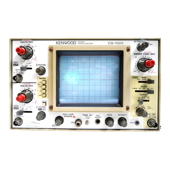
Page 8: Controls And Indicators
CONTROLS AND INDICATORS CS-1022, 1 0 2 1 , 1 0 1 2 C S - 1 0 2 0 , 1010 Fig. 2 Fig. 3 FRONT PANEL C S - 1 0 2 2 , 1 0 2 1 , 1 0 1 2... - Page 9 C S - 1 0 2 2 , 1 0 2 1 , 101.2 CS-1020, 1 0 1 0 © AC-GND-DC (4) AC-GND-DC Three-position lever switch which operates as follows: Three-position lever switch which operates as follows; A C : Blocks dc component of channel 1 input...
- Page 10 CS-1022, 1 0 2 1 , 1 0 1 2 Fig. 4 C S - 1 0 2 2 , 1 0 2 1 , 1 0 1 2 CS-1020, 1 0 1 0 MODE Five-position push switch; selects the basic operating modes of the oscilloscope.
- Page 11 C S - 1 0 2 2 , 1 0 2 1 , 1 0 1 2 CS-1020, 1 0 1 0 © GND terminal/binding post. (IJ) GND terminal/binding post. Earth and chassis ground. Earth and chassis ground. PROBE A D J . ©...
- Page 12 CS-1022, 1021, 1012 Fig. 5 C S - 1 0 2 0 , 1 0 1 0 C S - 1 0 2 2 , 1 0 2 1 , 1 0 1 2 COUPLING (§) COUPLING Three-position lever switch; selects coupling for sync Three-position lever switch;...
- Page 13 C S - 1 0 2 2 , 1 0 2 1 , 1 0 1 2 CS-1020, 1 0 1 0 CHOP: The display cannot be synchroniz- ed w i t h the input signal since the chopping signal becomes the trig- ger source.
-
Page 14: Rear Panel 1
Fig. 6 REAR PANEL C S - 1 0 2 2 , 1 0 2 1 , 1 0 1 2 C S - 1 0 2 0 , 1 0 1 0 Z AXIS INPUT (§) Z AXIS INPUT External intensity modulation input;... -
Page 15: Operation
Fig. 7 CS-1022, 1 0 2 1 , 1 0 1 2 CS-1020, 1 0 1 0 ( 1 ) NORMAL SWEEP DISPLAY OPERATION ( 1 ) NORMAL SWEEP DISPLAY OPERATION 1. - Page 16 •:'CSr1022, 1021, 1012 CS-1020, 1 0 1 0 one sweep displayes the channel 1 signal and the next provided signal of timing relationship to the observed sweep displays the channel 2 signal in an alternating se- signal, applying such a signal to the EXT TRIG INPUT jack. quence.
- Page 17 C S - 1 0 2 0 , 1 0 1 0 CS-1022. 1 0 2 1 . 1 0 1 2 signal being observed to synchronize the display. External • Triggering Level sync is prefered for waveform observation in many applica- Trigger point on waveform is adjusted by the LEVEL/PULL tions.
-
Page 18: Magnified Sweep Operation
ICS-1022, 1 0 2 1 , 1 0 1 2 CS-1020,, 1 0 1 0 (2) MAGNIFIED SWEEP OPERATION (2) MAGNIFIED SWEEP OPERATION Since merely shortening the sweep time t o magnify a por- Since merely shortening the sweep time to magnify a por- tion of an observed waveform can result in the desired por- tion of an observed waveform can result in the desired por- tion disappearing off the screen, such magnified display... -
Page 19: Application 1
APPLICATION PROBE COMPENSATION 2. Set the TRIG MODE to AUTO and AC-GND-DC t o the To obtain an accurate measurement result, the probe must GND position, which established the zero volt reference. be adjusted correctly before measurement. Using the • POSITION control, adjust the trace position 1 . -
Page 20: Measurements Of The Voltage Between Two Points On A Waveform 2
MEASUREMENT OF THE VOLTAGE BETWEEN TWO ELIMINATION OF UNDESIRED SIGNAL POINTS ON A WAVEFORM COMPONENTS (Unapplied to CS-1020 and 1 0 1 0 ) This technique can be used t o measure peak-to-peak The ADD feature can be conveniently used t o cancel out voltages. -
Page 21: Time Measurements 2
[EXAMPLE] For the example, the horizontal distance between the t w o points is 5.4 divisions. If the SWEEP TIME/DIV is 0.2 ms/div we calculate. (See Fig. 14) Substituting the given value: Time = 5.4 (div) x 0.2 (ms) = 1.08 ms FREQUENCY MEASUREMENTS Frequency measurements are made by measuring the period of one cycle of waveform and taking the reciprocal... -
Page 22: Pulse Width Measurements 2
by the number of cycles present in the given time span. Adjust t o the vertical scale If " x 10 M A G " is used multiply this further by 10. w i t h POSITION Note that errors will occur for displays having only a few cycles. -
Page 23: Time Difference Measurements 2
[EXAMPLE] Adjust t o the vertical scale For the example, the measured D is 1.8 divisions while D " w i t h POSITION is 2.2 divisions. If SWEEP TIME/DIV is 2 (is we use the following relationship. (See Fig. 19) Substituting the given value: Risetime = ( 1 . -
Page 24: Phase Difference Measurements 2
PHASE DIFFERENCE MEASUREMENTS (Unapplied Phase difference = Horizontal distance of new sweep range ( d i v ) x 4 5 ° / d i v to C S - 1 0 2 0 and 1 0 1 0 ) This procedure is useful in measuring the phase difference New SWEEP TIME/DIV setting of signals of the same frequency. - Page 25 Substituting the given value: 2. The vertical calibration coefficient is now the reference signal's amplitude (in volts) divided by the product of • • ,,. - 2 Vrms the vertical amplitude set in step 1 and the VOLTS/DIV Vertical coefficient = = 0 .
- Page 26 Unknown signal Fig. 24 [EXAMPLE] SWEEP TIME/DIV is 0.1 ms and apply 1.75 kHz reference signal. Adjust the VARIABLE so that the distance of one cycle is 5 divisions. Substituting the given value: Horizontal coefficient = = 1.142 5 x 0 . 1 (ms) Then, SWEEP TIME/DIV is 0.2 ms and horizontal amplitude is 7 divisions.
-
Page 27: Application Of X-Y Operation 2
A P P L I C A T I O N OF X - Y O P E R A T I O N CS-1022, 1 0 2 1 , 1 0 1 2 CS-1020, 1 0 1 0 •... - Page 28 C S - 1 0 2 2 , 1 0 2 1 . 1 0 1 2 * CS-1020, 1 0 1 0 No amplitude distortion, Amplitude distortion, No amplitude distortion, Amplitude distortion, 1 8 0 ° out of phase 1 8 0 °...
-
Page 29: Accessories
ACCESSORIES MOUNTING THE PROBE POUCH (MC-78) STANDARD ACCESSORIES INCLUDED This soft vinyl pouch attaches t o the right side of the Probe (PC-30) W 0 3 - 2 3 0 8 - 0 5 oscilloscope housing and provides storage space for t w o Attenuation 1/10, 1/1 probes and the operators manual. - Page 30 MEMO...
- Page 31 A p r o d u c t of KENWOOD CORPORATION 17-5, 2-chome, Shibuya, Shibuya-ku, Tokyo 150, Japan © PRINTED IN JAPAN B50-7570-30 (T) 91/12 11 10 9 8 7 6 5 4 3 2 1 90/12 11 1 0 9 8 7 6 5 4 3 2 1...