Advertisement
Quick Links
SERVICE MANUAL
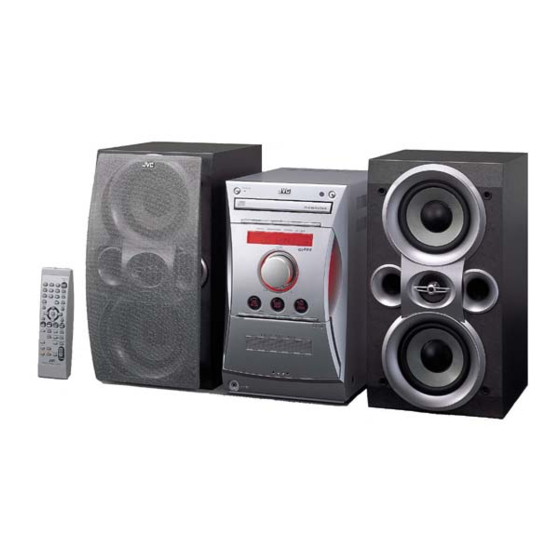
MICRO COMPONENT SYSTEM
UX-L40R/UX-L30R
STANDBY/ON
DISPLAY
CLOCK
/TIMER
SLEEP
BASS
TREBLE
UP
SET
DOWN
CANCEL
CD
TAPE
FM/AM
AUX/MD
AUTO
CD
REV.MODE FM MODE
PRESET
PRGM
RANDOM
REPEAT
PTY
SEARCH
SURROUND AHB PRO
+
DISPLAY
PTY
TA/News
SELECT
/Info
DIMMER
–
VOLUME
RM- SUXL40R REMOTE CONTROL
SP-UXL40
Contents
Safety precautions
Preventing static electricity
Important for laser products
Disassembly
Disassembly method
Main adjustment
STANDBY / ON
COMPACT
DIGITAL AUDIO
REC
SURROND
AHB PRO
CLOCK/TIMER
AUX/MD
MICRO COMPORNENT SYSTEM
UX-L40R
VOLUME
–
+
CD
TAPE
FM/AM
DOWN
UP
BASS
TREBLE
0
PUSH
OPEN
A U T O
R E V E R S E
PHONES
CA-UXL40R
SP-UXL40
1-2
1-4
1-5
1-6
1-15
1-23
COPYRIGHT
2002 VICTOR COMPANY OF JAPAN, LTD.
STANDBY/ON
1
2
3
4
5
6
DISPLAY
CLOCK
7
8
9
/TIMER
10
+10
SLEEP
BASS
UP
TREBLE
4
7
¢
SET
CANCEL
DOWN
3
8
23
/
CD
TAPE
FM/AM
AUX/MD
0
AUTO
CD
REV.MODE FM MODE
PRESET
PRGM
RANDOM
REPEAT
PTY
SEARCH
AHB PRO
+
DISPLAY
PTY
TA/News
SELECT
/Info
–
VOLUME
RM-SUXL30R REMOTE CONTROL
SP-UXL30
Flow of functional operation
until TOC read (CD)
Maintenance of laser pickup
Replacement of laser pickup
Description of major ICs
UX-L40R/UX-L30R
UX-L40R/UX-L30R
STANDBY / ON
COMPACT
DIGITAL AUDIO
REC
REV. MODE
AHB PRO
CLOCK/TIMER
AUX/MD
MICRO COMPORNENT SYSTEM
UX-L30R
VOLUME
–
+
CD
TAPE
FM/AM
DOWN
UP
BASS
TREBLE
0
PUSH
OPEN
A U T O
R E V E R S E
PHONES
CA-UXL30R
SP-UXL30
Area Suffix
B ---------------------------- U.K.
E -------- Continental Europe
EN ----------- Northem Europe
EV -------------- Eastem Europe
1-28
1-29
1-29
1-30~42
No.21070
Apr. 2002
1-1
Advertisement

Related Manuals for JVC UX-L40R


Summary of Contents for JVC UX-L40R
- Page 1 UX-L40R/UX-L30R UX-L40R/UX-L30R SERVICE MANUAL MICRO COMPONENT SYSTEM UX-L40R/UX-L30R STANDBY / ON STANDBY / ON COMPACT COMPACT DIGITAL AUDIO DIGITAL AUDIO SURROND AHB PRO CLOCK/TIMER AUX/MD REV. MODE AHB PRO CLOCK/TIMER AUX/MD MICRO COMPORNENT SYSTEM UX-L40R MICRO COMPORNENT SYSTEM UX-L30R VOLUME VOLUME –...
- Page 2 UX-L40R/UX-L30R 1. This design of this product contains special hardware and many circuits and components specially for safety purposes. For continued protection, no changes should be made to the original design unless authorized in writing by the manufacturer. Replacement parts must be identical to those used in the original circuits. Services should be performed by qualified personnel only.
- Page 3 UX-L40R/UX-L30R (U.K only) 1. This design of this product contains special hardware and many circuits and components specially for safety purposes. For continued protection, no changes should be made to the original design unless authorized in writing by the manufacturer.
- Page 4 UX-L40R/UX-L30R Preventing static electricity 1.Grounding to prevent damage by static electricity Electrostatic discharge (ESD), which occurs when static electricity stored in the body, fabric, etc. is discharged, can destroy the laser diode in the traverse unit (optical pickup). Take care to prevent this when performing repairs.
- Page 5 UX-L40R/UX-L30R Important for laser products 5.CAUTION : If safety switches malfunction, the laser is able 1.CLASS 1 LASER PRODUCT to function. 2.DANGER : Invisible laser radiation when open and inter 6.CAUTION : Use of controls, adjustments or performance of lock failed or defeated. Avoid direct exposure to beam.
- Page 6 UX-L40R/UX-L30R Disassembly method <Main body> Removing the Metal cover (See Fig.1 to 3) Remove the six screws A on the back of the main body. Remove the screw B on each side and remove the cover in the direction of the arrow.
- Page 7 UX-L40R/UX-L30R Removing the Rear cover (See Fig.4) Remove the metal cover. Remove the two screws C retaining the rear cover. Fig.4(UX-L30RE) Removing the Rear panel (See Fig.5) Remove the metal cover and the rear cover. Remove the ten screws D retaining the rear panel.
- Page 8 UX-L40R/UX-L30R Removing the Tuner board (See Fig.6) Remove the metal cover. Disconnect the card wire from connector CN1 on the tuner board. Remove the two screws E on the rear side and the screw F on the side. Tuner board Fig.6...
- Page 9 UX-L40R/UX-L30R Removing the CD-R/RW mechanism assembly (See Fig.8) Remove the metal cover, the rear cover, the rear panel, the tuner board and the optical digital board. CD-R/RW mechanism assembly Disconnect the card wire from connector CN903 and CN904 on the main board.
- Page 10 UX-L40R/UX-L30R CD-R/RW mechanism assembly CN905 CN902 CN904 CN903 Removing the Main board/ the Heat sink board (See Fig.9 to 11) Remove the metal cover, the rear cover and the rear panel. Disconnect the card wire from connector CN902, CN903, CN904 and CN905 on the main board and remove the CD-R/RW mechanism assembly.
- Page 11 UX-L40R/UX-L30R Removing Power transformer assembly (See Fig.12) Remove the metal cover, the rear cover, the rear panel, the CD-R/RW mechanism assembly and the main board. Disconnect the power cord from connector J1000 on the power transformer assembly. Remove the four screws J.
- Page 12 UX-L40R/UX-L30R Front panel assembly Removing the Front panel assembly (See Fig.13 to 16) Remove the metal cover. Remove the screw K on each side. Pull the joint h on both sides and lift the front panel assembly to release the joint g.
- Page 13 UX-L40R/UX-L30R Removing the Phones board (See Fig.17) Prior to performing the following procedure, remove the metal cover and the front panel assembly. Disconnect connector CN913 on the main board. Main board CN913 Phones board Fig.17 Removing the Cassette mechanism assembly (See Fig.18)
- Page 14 UX-L40R/UX-L30R Removing the Control board (See Fig.19) Prior to performing the following procedure, remove the metal cover and the front panel assembly. Remove the seven screws M to remove the control board. Control board Fig.19 Removing the Volume board (See Fig.20 and 21) Prior to performing the following procedure, remove the metal cover and the front panel assembly.
- Page 15 UX-L40R/UX-L30R <CD mechanism assembly section> CD servo board Removing the CD servo board (See Fig.1, 2) CN601 CAUTION: Solder the shorting round before disconnecting the card wire extending from the pickup. If you do not follow this instruction, the pickup may be damaged.
- Page 16 UX-L40R/UX-L30R Removing the clamper base / tray Joint a Fitting Joint a (See Fig.3 ~ 5) Bring up the fitting in the direction of the arrow to release the three joints a. On the front side of the body, move the cam plate lever to the center.
- Page 17 UX-L40R/UX-L30R Removing the CD mechanism assembly (See Fig.6, 7) CD mechanism assembly Prior to performing the following procedure, remove damper damper the clamper base / tray and the CD servo board. Remove the screw D attaching the CD mechanism assembly.
- Page 18 UX-L40R/UX-L30R Removing the loading motor / loading motor board (See Fig.8, 9) Loading motor Prior to performing the following procedure, remove the clamper base / tray and the CD servo board. From upside of the loading base, remove the belt from the motor pulley.
- Page 19 UX-L40R/UX-L30R Removing the C.D. gear (1), (2) and (3) CD base (See Fig.10 ~ 13) Prior to performing the following procedure, remove the CD servo board. Remove the two screws F attaching the CD base on the bottom of the loading base.
- Page 20 UX-L40R/UX-L30R <Cassette mechanism section> Cassette mechanism Removing the playback / recording & eraser head (See Fig. 1 ~ 3) While shifting the trigger arms seen on the right side of the head mount in the arrow direction, turn the flywheel R in counterclockwise direction until the Flywheel (R) head mount has gone out with a click (See Fig.
- Page 21 UX-L40R/UX-L30R Removing the head amplifier & mechanism control board (See Fig. 4) Belt Remove the cassette mechanism assembly. CN32 Main motor assembly After turning over th cassette mechanism assembly, remove the three screws A retaining the head amplifier & mechanism control board.
- Page 22 UX-L40R/UX-L30R Removing the flywheel (See Fig. 7, 8) Remove the head amplifier & mechanism control P.C. board. Remove the main motor assembly. After turning over the cassette mechanism, remove Flywheel (R) Flywheel (L) the two slit washers and fixing the capstan shafts R and L, and pull out the flywheel (R) and (L) respectively from behind the cassette mechanism.
- Page 23 UX-L40R/UX-L30R Adjustment method Measurement Instruments Required for Tuner section Adjustment FM Band cover: 87.5 108MHz 1. Low frequency oscillator MW Band cover: 522 1,629kHz LW Band cover: 144 288kHz This oscillator should have a capacity to output 0dBs to 600...
- Page 24 UX-L40R/UX-L30R << >> Arrangement of Adjusting Position Cassette mechanism section Cassette mechanism section (Back side) Head azimuth Head azimuth adjusting screw adjusting screw (Forward side) (Reverse side) Head azimuth Head azimuth Playback/Recording & adjusting screw adjusting screw eraser head (Forward side)
- Page 25 UX-L40R/UX-L30R Tape Recorder Section Measurement Adjusting Standard Items Measurement method conditions positions Values Adjust the head Confirmation Test tape 1 Playback the test tape VTT703L (8kHz) Maximum azimuth screw of head angle : VTT703L (8kHz) 2 With the recording & playback mechanism,...
- Page 26 UX-L40R/UX-L30R Electrical Performance Adjusting Measurement Standard Items Measurement method positions conditions Values VR31 AC-225 Adjustment of Mode: Forward or 1 With the recording and playback : 4.20 recording bias reverse mode mechanism, load the test tapes (AC-514 to AC-514 current...
- Page 27 UX-L40R/UX-L30R Extension code connecting method CD mechanism assembly 1-27...
- Page 28 UX-L40R/UX-L30R Flow of functional operation until TOC read (CD) Check Point Slider turns REST Power Key Power ON Check that the voltage at the pin4 SW ON. of CN601 is 0V (a moment)? Automatic tuning of TE offset Check that the voltage at the...
- Page 29 UX-L40R/UX-L30R Maintenance of laser pickup Replacement of laser pickup (1) Cleaning the pick up lens Befor you replace the pick up, please try to Turn off the power switch and,disconnect the clean the lens with a alcohol soaked cotton power cord from the ac outlet.
- Page 30 UX-L40R/UX-L30R Description of major ICs LA1838 (IC1) : FM AM IF amp & Detector, FM MPX decoder 1. Block diagram DECODER RF.AMP ANIT-BIRDIE MUTE BUFF STEREO P-DET AM IF PILOT 384KHz COMP S-METER AM/FM S-CLRVE S-METER IF-BUFF TUNING STEREO DRIVE...
- Page 31 UX-L40R/UX-L30R LC72136N (IC2) : PLL frequency synthesizer 1. Pin layout FM/AM LPFOUT LPFIN CLOCK FM/ST/VCO FMIN AM/FM AMIN IFCONT SDIN IFIN 2. Block diagram Phase Reference Detector Driver Charge Pump Swallow Counter Swallow Counter 1/16,1/17 4bit 1/16,1/17 4bit Unlock Detector...
- Page 32 UX-L40R/UX-L30R LA72723 (IC3) : RDS demodulation 1. Pin layout RDS-ID/READY VREF RDCL MPXIN RDDA Vdda Vssa MODE FLOUT Vddd Vssd XOUT 2. Block diagram FLOUT VREF Vdda CLOCK Vddd RECOVERY (1187.5Hz) REFERENCE (57kHz) VOLTAGE Vssa Vssd VREF 57kHz MPXIN (SCF)
- Page 33 UX-L40R/UX-L30R LA6541-X (IC801) : Servo driver 1. Pin Layout & block diagram Vref Vin4 Vin3 Level B T L B T L Level RESET shift driver driver shift Level B T L B T L Level Regulator shift driver driver...
- Page 34 UX-L40R/UX-L30R LC75345M-X (IC901) : E.volume 1. Pin layout 36 35 34 33 32 31 30 29 28 27 26 25 24 23 22 21 20 19 2. Block diagram LINP LINM LVref LOPOUT CONTROL CIRCUIT LOGIC Vref INTERFACE CIRCUIT CONTROL...
- Page 35 UX-L40R/UX-L30R 3. Pin function Pin No. Symbol Function Serial data and clock input pin for control. Chip enable pin. Ground pin. LOPOUT Output pin of general-purpose operation amplifier. LINM Non-inverted input pin of general-purpuse operation amplifier. LINP Non-inverted input pin of general-purpuse operation amplifier.
- Page 36 UX-L40R/UX-L30R AN7317 (IC32) : R/P amp. 1. Pin layout & block diagram 112k Mute 112k 2. Pin functions Pin No. Function Channel 1 playback amplifier input Channel 1 playback amplifier negative feedback Channel 1 playback amplifier output Channel 1 record amplifier input...
- Page 37 UX-L40R/UX-L30R TDA7294 (IC940, IC941) : Audio amp. 1. Pin layout -Us (POWER) +Us (POWER) N.C. N.C. MUTE STAND-BY -Us (SIGNAL) +Us (SIGNAL) BOOTSTRAP N.C. NON INUERTING INPUT INVERTING INPUT STAND-BY GND 2. Block diagram BOOTSTRAP BOOTSTRAP OUTPUT BIPOLAR MOS GHAIN &...
- Page 38 UX-L40R/UX-L30R L4909 (IC942) : Regulator 1. Pin layout 9 10 11 12 13 14 15 2. Block diagram VINA THERMAL REFERENCE VINB 3,13 REF+20% SHUTDOWN GENERATOR REG1 REG1 ENABLE REG2 CONTROL REG3 REG2 OVER CURRENT CHECK TRIG REG3 3. Pin functions Pin No.
- Page 39 UX-L40R/UX-L30R KIA78S06P-T (IC932) : Regulator 1. Pin layout 2. Block diagram 3 INPUT 1 2 3 1 OUTPUT 2 COMMON BU4094BCF-X (IC33) : Shift/store registor 1. Pin layout 2. Block diagram DATA SERIAL 8-STAGE OUTPUT OUTPUT ENABLE SHIFT REGISTER CLOCK...
- Page 40 UX-L40R/UX-L30R MN662748RPMFA (IC651) : DSP 1. Terminal layout 80~61 21~40 2. Pin function Symbol Function Symbol Function 1 BCLK Not use 41 PLLF2 Not use 2 LRCK Not use 42 TOFS Not use 3 SRDATA Not use 43 WVEL Not use...
- Page 41 UX-L40R/UX-L30R AN22000A-W (IC601) : RF head amp. 1. Pin layout 9 10 11 12 13 14 15 16 2. Block diagram 3TOUT NRFDET FEOUT TEOUT TEBPF VDET VREF 3. Pin function Pin No. Function Pin No. Function APC amp input terminal.
- Page 42 UX-L40R/UX-L30R MN101C38CEK1 (IC931) : Micro controller 1. Pin layout 2. Pin Function Pin No. Symbol Function Pin No. Symbol I/O Function LCD Bias co mmon LCD DIM control. DIMMER ON =L COM3~0 DIMCTL LCD Bias voltage VLC3~1 LEDCTL Power standby LED control...
- Page 43 UX-L40R/UX-L30R < M E M O > 1-43...
- Page 44 UX-L40R/UX-L30R UX-L40R/UX-L30R VICTOR COMPANY OF JAPAN, LIMITED AUDIO & COMUNICATION BUSINESS DIVISION PERSONAL & MOBILE NETWORK BUSINESS UNIT. 10-1,1chome,Ohwatari-machi,Maebashi-city,371-8543,Japan Printed in Japan 1-44 (No.21070) 200204...
- Page 45 UX-L40R/UX-L30R Block diagram FMH-036-3 FMA-006 IFOUT FMC-028 FMH-036-4 ONLY FOR IC901 OSCOUT MUTE/IFOUT B/E/EN/EV LOUT REMOCON FM RF MATRIX MATRIX FM/AM ONLY TUL,TUR ROUT FM/AM SQIN FMDET KEY1 FMH-036-1 KEYD COM0-3, ST/MONO AM DET ONLY FOR S0-S34 AMOSC AMRF TUDATA...
- Page 46 UX-L40R/UX-L30R UX-L40R/UX-L30R Standard schematic diagrams Front circuit CN904 CN903 QGF1205F1-16 QGF1205F1-13 R2503 R2502 *R7511 R7503 R7504 R7505 R7506 R7507 R7508 R7509 1.2K 1.8K 2.2K 2.7K 3.9K C7506 2SC2785/FE/-T QUM026-11DGZ4 Q7031 FW750 0.01 R7155 R7157 ROUT R7151 R7149 LOUT R7147 GP1UM-261XK...
- Page 47 UX-L40R/UX-L30R Main circuit CN915 CN916 CN917 CN918 QGB2510J1-10 QGB2510J1-11 QGD2504C1-03Z QGD2504C1-03Z C2119 0.27 R2803 22/16 C2117 QSK0109-001 B2094 KTC3199/GL/-T C2215 RY901 22/16 Q2800 470( 1W) 150K R2147 L2800 R2801 R2802 0.012 QQR0797-001 C2126 1/50 R2702 C2702 D2701 R2712 IC901 330K...
- Page 48 UX-L40R/UX-L30R UX-L40R/UX-L30R Subwoofer circuit IC940 IC941 TDA7294 TDA7294 D4219 DZ8.2BSC-T2 C4204 R4000 C4004 C4000 C4001 C4005 R4001 C4203 100p 100p 22/50 22/50 100/16 C4002 10/50 D4221 R4012 R4010 R4013 R4011 C4018 C4013 DZ11BSB-T2 10/50 1.2K 10/50 1.2K C4202 C4010 C4011...
- Page 49 UX-L40R/UX-L30R CD servo circuit J902 GP1FA550TZ CN905 QGA2501F1-03 W605 QJP001-031200 R601 270K TBAL R602 680K FBAL GCTRL 0.022 C604 0.022 C603 R604 180K C606 R643 0.047 C641 STAT C601 560K R642 VDET SQCK C602 0.0022 LDON SUBQ C633 C653 MCLK 0.022...
- Page 50 UX-L40R/UX-L30R UX-L40R/UX-L30R Cassette amplifier circuit 1SR139-400-T2 SG-105F3-BB,C C211 R212 2.2K 0.0015 C208 R208 R211 C204 R203 R202 5.6K 4.7/25 0.033 2.4K 1.8K R204 1.2K MSI-5U2LWA QGB2011L1-10 IC31 BA3126N R304 FW31 CN32 QGB2011M1-10 VWS304-06A13K R301 IC32 AN7317 LV42902-001A R207 R371 R107 R104 1.2K...
- Page 51 UX-L40R/UX-L30R Tuner circuit QAU0160-001 0.0039 0.47/50 0.0022 0.047 22/16 0.27 470P 1/50 0.047 22/16 10/16 0.001 10/16 1SS133-T2 100/10 1000P 1SS133-T2 0.0018 0.0018 3.3K QAX0420-001 LC72136N 1SS133-T2 LA1838 2SC2412K/R/-X 2SC2412K/R/-X 1SS133-T2 QNB0014-001 DTA114YKA-X QAX0458-001Z 5.6K DTA114YKA-X 150P QQR0793-001 150P 150P 1/50 1.2K...
- Page 52 UX-L40R/UX-L30R UX-L40R/UX-L30R Power supply circuit FW950 CN951 QUM156-15DGZ4 QGD2504C1-03Z Q1000 2SC2785 2SC2235 Q1001 DZ6.8BSB-T2 C1009 D1011 0.0047 470/16 R1002 C1010 C1011 1000/25 D1012 R1003 R1004 4.7K 1SS119-041-T2 F1000 Q1002 C1012 KTC3199/GL/-T 10/25 J1000 QGA7901C1-02 Parts are safety assurance parts. When replacing those parts make...
- Page 53 UX-L40R/UX-L30R Printed circuit boards Main board...
- Page 54 UX-L40R/UX-L30R UX-L40R/UX-L30R Front board 2-10...
- Page 55 UX-L40R/UX-L30R CD servo board 2-11...
- Page 56 UX-L40R/UX-L30R Tuner board 2-12...
- Page 57 UX-L40R/UX-L30R Head amplifier board Cassette switch board 2-13...
- Page 58 UX-L40R/UX-L30R PARTS LIST [ UX-L40R ] [ UX-L30R ] * All printed circuit boards and its assemblies are not available as service parts. Area suffix B ------------------------------- U.K. E ----------- Continental Europe EN ------------ Northern Europe EV -------------- Eastern Europe...
- Page 59 UX-L40R/UX-L30R < M E M O >...
- Page 60 UX-L40R/UX-L30R Exploded view of general assembly and parts list Block No. Input board Tuner board board Volume board Power trans board Control board Heat shink board...
- Page 61 CD MECHA ASSY GV30318-001A RATING LABEL 1 UX-L40R B,E,EN GV10102-001A CLAMPER BASE GV30318-002A RATING LABEL 1 UX-L40R MAGNET VYH7313-005 GV30276-002A RATING LABEL 1 UX-L30R CD YOKE E306836-223SS QUQ412-0914CJ FFC WIRE 1 UX-L30R FC33 VYH1240-001 TRAY QUQH12-0914AJ FFC WIRE 1 UX-L40R FC33...
- Page 62 Parts list (General assembly) Block No. M1MM Item Parts number Parts name Q'ty Description Area QUQH12-1018AJ FFC WIRE 1 UX-L40R FC34 QUQ412-1018CJ FFC WIRE 1 UX-L30R FC34 QUQ412-1314DJ FFC WIRE 1 UX-L30R FC652 QUQH12-1314BJ FFC WIRE 1 UX-L40R FC652 QUQH12-1614BJ...
- Page 63 UX-L40R/UX-L30R CD loading base assembly and parts list Block No. LOAD-JEM-2M Grease = G-474C = EBS0006-009B FIG A Apply grease to groove and support convex. FIG A Dimension gap for motor pulley...
- Page 64 UX-L40R/UX-L30R Parts list (CD loading base) Block No. MDMM Item Parts number Parts name Q'ty Description Area VYH1238-001 LODING BASE MMN-6F1LB8K MOTOR QGF1201F3-05 CONNECTOR 1 CN505 QSW0472-001 SWITCH 1 S851 QYSPSPT2640Z MINI SCREW E75984-221SS CD M.PULLEY BELT E75950-002 E75985-221SS CD GEAR (1)
- Page 65 UX-L40R/UX-L30R Cassette mechanism assembly and parts list Block No. SLC-S101M Grease = EM-30L =UD-24 =UD-24H2 =LEN-320M =JC-888B =MOBIL-1 The lower side Switch board Head amplifier board...
- Page 66 UX-L40R/UX-L30R Parts list (Cassette mechanism) Block No. MPMM Item Description Parts number Parts name Q'ty Area VKS1165-00J CHASSIS B.ASS'Y VKS2274-002 REEL GEAR VKW5286-002 B.T. SPRING PLAY IDLE GEAR VKS5559-001 VKS5595-002 BLIND VKS5560-003 FR IDLE GEAR LV42013-001A EARTH SPRING SLC-RP3SVM HEAD MOUNT VKY3149-002 CASSETTE SP.
- Page 67 UX-L40R/UX-L30R Electrical parts list (Input board) Block No. 01 Item Parts number Parts name Remarks Area Item Parts number Parts name Remarks Area CN900 QGF1201C3-10 CONNECTOR C2820 QCBB1HK-222Y C CAPACITOR 2200PF 10% 50V CN901 QGF1205C1-09 CONNECTOR C2821 QCBB1HK-222Y C CAPACITOR...
- Page 68 UX-L40R/UX-L30R Electrical parts list (Input board) Block No. 01 Item Parts number Parts name Remarks Area Item Parts number Parts name Remarks Area L2500 QQL231K-820Y INDUCTOR R2140 QRE141J-471Y C RESISTOR 470 5% 1/4W L2501 QQL231K-820Y INDUCTOR R2141 QRE141J-182Y C RESISTOR 1.8K 5% 1/4W...
- Page 69 UX-L40R/UX-L30R Block No. 01 Electrical parts list (Input board) Item Remarks Parts number Parts name Area R7116 QRE141J-222Y C RESISTOR 2.2K 5% 1/4W R7117 QRE141J-103Y C RESISTOR 10K 5% 1/4W R7118 QRE141J-222Y C RESISTOR 2.2K 5% 1/4W R7119 QRE141J-823Y C RESISTOR...
- Page 70 UX-L40R/UX-L30R Electrical parts list (Main board) Block No. 02 Item Parts number Parts name Remarks Area Item Parts number Parts name Remarks Area CN731 QGF1201F3-23 CONNECTOR C7351 QDYB1CM-103Y C CAPACITOR CN732 QGF1201F3-23 CONNECTOR C7352 QDYB1CM-103Y C CAPACITOR CN905 QGA2501F1-03 CONNECTOR...
- Page 71 UX-L40R/UX-L30R Electrical parts list (Main board) Block No. 02 Item Parts number Parts name Remarks Area Item Parts number Parts name Remarks Area Q1002 KTC3199/GL/-T TRANSISTOR R4206 QRE141J-122Y C RESISTOR 1.2K 5% 1/4W Q4000 2SC3576-JVC-T TRANSISTOR R4207 QRE141J-820Y C RESISTOR...
- Page 72 UX-L40R/UX-L30R Electrical parts list (CD board) Block No. 03 Item Parts number Parts name Remarks Area Item Parts number Parts name Remarks Area C 601 NCB31CK-104X C CAPACITOR CN651 QGF1205F1-16 CONNECTOR C 602 NCB31HK-222X C CAPACITOR CN652 QGF1205F1-13 CONNECTOR C 603...
- Page 73 UX-L40R/UX-L30R Block No. 03 Electrical parts list (CD board) Item Remarks Parts number Parts name Area R 805 NRSA63J-912X MG RESISTOR R 806 NRSA63J-513X MG RESISTOR R 807 NRSA63J-392X MG RESISTOR R 808 NRSA63J-563X MG RESISTOR R 821 NRSA63J-0R0X MG RESISTOR...
- Page 74 UX-L40R/UX-L30R Electrical parts list (Tuner board) Block No. 04 Item Parts number Parts name Remarks Area Item Parts number Parts name Remarks Area CF 1 QAX0420-001 C FILTER NCB21HK-223X C CAPACITOR CF 2 QAX0458-001Z C FILTER NCB21HK-103X C CAPACITOR CF 3...
- Page 75 UX-L40R/UX-L30R Electrical parts list (Head amplifier board) Block No. 05 Item Parts number Parts name Remarks Area Item Parts number Parts name Remarks Area C 101 NCS21HJ-821X C CAPACITOR R 103 NRSA63J-242X MG RESISTOR C 102 NCS21HJ-221X C CAPACITOR R 104...
- Page 76 UX-L40R/UX-L30R < M E M O > 3-19...
- Page 77 UX-L40R/UX-L30R Packing materials and accessories parts list Block No. Block No. A1~A7,A10,A11 UX-L40R ONLY A8, A9 A8, A9 A8, A9 A8, A9 3-20...
- Page 78 715-250068-00 MIRAMAT SHEET 2 UX-L40R 715-250009-00 MIRAMAT SHEET 2 UX-L30R 700-120074-10 POLY BAG 2 UX-L30R FOR SPK 700-120073-10 POLY BAG 2 UX-L40R FOR SPK P 10 GV40168-005A SHEET P 11 GV40341-001A SPACER 1 CASS. DOOR/F.PANEL P 12 GV40256-002A SPACER 1 UX-L40R Parts list (Accessories) Block No.