Advertisement
Quick Links
I N S P I R E D O U T D O O R L I V I N G
I N S P I R E D O U T D O O R L I V I N G
DANGER
If you smell gas:
• Shut off gas to the appliance.
• Extinguish any open flame.
• If odor continues, keep away from the
appliance and immediately call your gas
supplier or fire department.
Failure to follow these instructions could result in
fire or explosion, which could cause property
damage, personal injury, or death.
DANGER
Do not store or use gasoline or other flammable vapors
and liquids in the vicinity of this or any other appliance.
A propane-cylinder not connected for use shall not be
stored in the vicinity of this or any other appliance.
WARNING
Improper installation, adjustment, alteration, service or
maintenance can cause property damage, injury or
death.
Read the installation, operating and maintenance
instructions thoroughly before installing or servicing
this equipment.
WARNING: For Outdoor Use Only.
Installation and service must be performed by a
qualified installer, service agency, or the gas supplier.
CARBON MONOXIDE HAZARD
This appliance can produce
DANGER
carbon monoxide which has no
odor.
Using it in an enclosed space can
kill you.
Never use this appliance in an
enclosed space such as a
camper, tent, car or home.
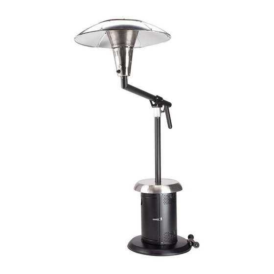
PERFECT POSITION PROPANE
PATIO HEATER
MODEL NO: COH-400
Customer Service Hotline
1-866-994-6390
DO NOT RETURN PRODUCT
TO THE STORE
Before visiting your local retailer, please email
grilling@thefulhamgroup.com, call 1-866-994-6390,
or visit www.thefulhamgroup.com to online chat with a
representative. To best serve you, our Representatives
are available to answer your calls and live chats
Monday to Friday, 9 AM - 5 PM EST.
INSTALLER: Leave this manual with the appliance.
CONSUMER: Retain this manual for future
reference.
CALIFORNIA PROPOSITION 65 WARNING:
• WARNING: FUELS USED IN LIQUEFIED PROPANE
GAS APPLIANCES, AND THE PRODUCTS OF
COMBUSTION OF SUCH FUELS, CAN EXPOSE YOU
TO CHEMICALS INCLUDING BENZENE, WHICH IS
KNOWN TO THE STATE OF CALIFORNIA TO CAUSE
CANCER AND CAUSE BIRTH DEFECTS OR OTHER
REPRODUCTIVE HARM.
For more information go to:
www.P65Warnings.ca.gov.
Advertisement

Related Manuals for Cuisinart COH-400

Summary of Contents for Cuisinart COH-400
-
Page 1: Cover Page
I N S P I R E D O U T D O O R L I V I N G I N S P I R E D O U T D O O R L I V I N G MODEL NO: COH-400 DANGER If you smell gas: •... -
Page 2: Safety Information
SAFETY INFORMATION WARNINGS AND USAGE IMPORTANT: ALL INSTRUCTIONS AND SAFEGUARDS ON THIS SECTION MUST BE FOLLOWED TO PREVENT DAMAGE AND/OR INJURY. USE CAUTION AND COMMON SENSE WHEN USING YOUR OUTDOOR PATIO HEATER. FAILURE TO ADHERE TO THE SAFETY WARNING AND GUIDELINES IN THE MANUAL COULD RESULT IN BODILY INJURY OR PROPERTY DAMAGE. - Page 3 SAFETY INFORMATION •Ensure aerosols are not used near this unit when in use. •Ensure all packaging and plastic bags are disposed of safely. •Ensure the heater is at a safe distance from glass and PVC doors and windows to stop damage from any heat. •Read the warnings and use instructions before operation.
- Page 4 SAFETY INFORMATION • CAUTION: Do not touch the heating dome when burner is in operation, allow to cool down completely before touching. • CAUTION: Do not walk under burner head while it is in raised position. • WARNING: Before allowing anyone to operate the heater, be certain that they have fully understood the manual. •...
-
Page 5: Table Of Contents
TABLE OF CONTENTS Cover Page.……......…………..………………………….………...….………….………….….…………………..……..1 Safety Information……….….....……………………...………...….………….….………….………......……..……..2 Table of Contents……...…….……………………..….………...….…………......………………..……….…….…..5 Exploded View……....………….…………………….…………………….......……….………........6 What’s in the Box….………......……..…..….……...…....……………..………………........7 Assembly Instructions…......…………………...……………………….….…......…........9 Operation…................…..……..……………………......…....17 Care and Maintenance....…......……….………………..…………….……...….….…........22 Warranty and Replacement Parts…..………..……….……………………..…………..………......……...23... -
Page 6: Exploded View
EXPLODED VIEW Carefully remove all pieces from the carton and make sure that you have all parts listed (refer to components list). If you are missing parts, please contact 1-866-994-6390 for further assistance. Use caution when removing the parts from packaging. It is recommended to wear gloves when assembling and handling loose parts. -
Page 7: What's In The Box
WHAT’S IN THE BOX COMPONENTS PART DESCRIPTION PART DESCRIPTION Base (x1) Upper Support Pole (x1) Cylinder Chamber Supports (A, B, C) (x3) Main Burner and Hose (x1) Lower Support Pole (x1) Burner Mesh (x1) Cylinder Chamber Wall (x1) Parasol Supports (x3) Cylinder Chamber Door (x1) - Page 8 PRE-ASSEMBLY PLANNING ASSEMBLY When you are ready to start, make sure that you have the right tools at hand, plenty of space and a clean dry area for assembly. WARNING: While every precaution has been made in the manufacture of this product, care must be taken during assembly in case sharp edges are present.
-
Page 9: Assembly Instructions
ASSEMBLY INSTRUCTIONS STEP 1 ASSEMBLING THE LEGS STEP 2 ATTACHING THE LOWER SUPPORT POLE •Attach the cylinder chamber supports (2) to the •Attach the lower support pole (3) to the cylinder corresponding section on the base (1) with six of the chamber supports (2) using six bolts (CC) and nuts bolts (CC). - Page 10 ASSEMBLY INSTRUCTIONS STEP 3 ATTACHING THE CYLINDER CHAMBER WALL STEP 4 ATTACHING THE CYLINDER CHAMBER DOOR •Using six of the bolts (AA) and nuts (BB), attach the •Hang the cylinder chamber door (5) on the hinges. cylinder chamber wall (4) to the cylinder chamber •Ensure that the alignment is correct and tighten all supports (2).
- Page 11 ASSEMBLY INSTRUCTIONS STEP 5 ATTACHING THE CYLINDER CHAMBER TOP STEP 6 ATTACHING THE PARASOL SUPPORTS •Slide the cylinder chamber top (6) down over the •Attach the three parasol supports (11) to the burner lower support pole (3) as shown and secure to the mesh (10) using six of the pre-fitted bolts.
- Page 12 ASSEMBLY INSTRUCTIONS STEP 8 ATTACHING THE LANTERN STEP 7 ASSEMBLING THE LANTERN •Lower the burner mesh (10) onto the main burner •Feed the hose down through the upper support pole (9) and secure with three of the pre-fitted bolts. (8) and secure the assembled lantern to the upper support pole (8) using four bolts (CC), washers (DD) and spring washers (GG).
- Page 13 ASSEMBLY INSTRUCTIONS STEP 9 ATTACHING THE HANDLE STEP 10 ATTACHING THE SWIVEL HEAD •Attach the handle (12) to the upper support pole (8) •Attach the swivel head (7) to the upper arm using three bolts (CC), washers (DD) and spring assembly using the pre-fitted bolt, as shown below.
- Page 14 ASSEMBLY INSTRUCTIONS STEP 11 ASSEMBLING THE UPPER SECTION STEP 12 ATTACHING THE REGULATOR AND PROPANE BOTTLE •Feed the hose down through the lower support pole NOTE: THE CYLINDER MUST BE POSITIONED AS (3) and lower the upper arm assembly, attaching the SHOWN IN THE PATIO HEATER CYLINDER swivel head (7) to the lower support pole (3) using CHAMBER TO PROVIDE VAPOR WITHDRAWAL.
- Page 15 ASSEMBLY INSTRUCTIONS STEP 13 ASSEMBLING THE REFLECTOR STEP 14 ATTACHING THE REFLECTOR TO THE LANTERN WARNING: While every precaution has been made in •Fit the reflector to the lantern using three bolts the manufacture of this product, care must be taken (FF) and washers (EE).
- Page 16 ASSEMBLY INSTRUCTIONS STEP 15 SECURING THE UPPER SECTION STEP 16 FITTING THE BATTERY •Raise the upper arm upwards and secure using •Unscrew sparker button (A) and insert battery (B), the pre-fitted pin. positive side facing outwards.
-
Page 17: Operation
OPERATION Fig. 1 •Beware of the pinch point between the burner arm (horizontal rod) and the vertical pole, when lowering and raising the head (Fig.1). •Certain materials or items, when stored under the heater, will be subjected to radiant heat and could be seriously damaged. •Inspect the visible portion of the hose before each use of the appliance. - Page 18 OPERATION (CONTINUED) •Keep this appliance away from any flammable materials! •Important - Make sure the propane tank is placed level within the base. •Should you need to change the gas bottle, confirm the gas supply is turned off at the regulator or bottle / cylinder valve, and there are no sources of ignition (cigarettes, open flame, sparks, etc.) near before proceeding.
- Page 19 OPERATION (CONTINUED) RAISING AND LOWERING THE BURNER HEAD To fold the burner head down, Ensure that the swivel lock is in position the lantern opposite the lock position. the wheels as shown above. Remove the lock pin and gently Put the lock pin back into lower down the burner head.
- Page 20 OPERATION (CONTINUED) BEFORE LIGHTING 1. Inspect the visible portion of the hose before each use of the appliance. 2. Inspect the entire hose assembly at least annually. If disassembly is required, perform a leak test to check the connections upon re-assembly. Inspect the portion of the hose that is not visible. The hose assembly must be replaced prior to the appliance being put into operation.
- Page 21 OPERATION (CONTINUED) •A slight leak could cause a fire. •If no bubbles appear after one minute, turn the tank OFF, wash off soapy solution with cold water and towel dry. •Leak test annually and whenever the gas bottle is removed or replaced. WARNING: When leak testing this appliance, make sure to test and tighten all loose connections.
-
Page 22: Care And Maintenance
CARE AND MAINTENANCE STORAGE •Do not leave the patio heater exposed to outside weather conditions or stored in damp moist conditions. •To save space during long-term storage, the reflector can be removed. Take care to ensure the shape of the reflector is not damaged or deformed, as this will affect performance. -
Page 23: Warranty And Replacement Parts
WARRANTY AND REPLACEMENT PARTS EXPLODED VIEWS Top Panel (Dome) Side Panels (6) Parasol Supports Thermocouple / Tiltswitch Assembly Burner Mesh Upper Support Main Burner and Hose Pole Control Knob (Burner) Ignitor Button / Battery Contact Swivel Bolt Lock Pin Swivel Handle Head Hose... - Page 24 WARRANTY AND REPLACEMENT PARTS PARTS LIST PART DESCRIPTION PART DESCRIPTION S60059 S60072 Base Handle S60060 S60073 Cylinder Chamber Support A Regulator S60061 S60074 Cylinder Chamber Support B Top Panel (Dome) S60062 S60075 Cylinder Chamber Support C Side Panels (6) S60063 S60076 Lower Support Pole Lock Pin...
- Page 25 1-866-994-6390 from 9:00am to 5:00pm Eastern time, Monday through Friday. ©2021 Cuisinart Cuisinart® is a registered trademark under license to The Fulham Group. Get Social With Us @CuisinartBBQ Distributed by The Fulham Group, Newton, MA. 02466 U.S.A.