Table of Contents
Advertisement
Quick Links
Advertisement
Table of Contents

Related Manuals for Bosch Rexroth VFC 3210


Summary of Contents for Bosch Rexroth VFC 3210
- Page 1 Frequency Converter VFC 3210 Operating Instructions Edition 01 R912007862...
- Page 2 Edition 01 Edition 01 Copyright © Bosch Rexroth (Xi'an) Electric Drives and Controls Co., Ltd. 2018 All rights reserved, also regarding any disposal, exploitation, reproduction, edit- ing, distribution, as well as in the event of applications for industrial property rights.
- Page 3 VFC 3210 Bosch Rexroth AG Deutsch English Français Lebensgefahr bei Danger to life in Danger de Nichtbeachtung der nachstehenden case of non‑compliance with the mort en cas de non‑respect des Sicherheitshinweise! below-mentioned safety consignes de sécurité figurant ci- instructions! après !
- Page 4 Bosch Rexroth AG VFC 3210 Deutsch English Français Electromagnetic / Champs Elektromagnetische / magnetische magnetic fields! Health hazard for électromagnétiques / magnétiques ! Felder! Gesundheitsgefahr für persons with heart pacemakers, Risque pour la santé des porteurs de Personen mit Herzschrittmachern, metal implants or hearing aids! stimulateurs cardiaques, d’implants...
- Page 5 VFC 3210 Bosch Rexroth AG Español Português Italiano Pericolo di ¡Peligro de Perigo de vida em morte in caso di inosservanza delle muerte en caso de no observar las caso de inobservância das seguintes seguenti indicazioni di sicurezza! siguientes indicaciones de instruções de segurança!
- Page 6 Bosch Rexroth AG VFC 3210 Español Português Italiano Campi ¡Campos Campos elettromagnetici / magnetici! Pericolo electromagnéticos/magnéticos! eletromagnéticos / magnéticos! per la salute delle persone portatrici ¡Peligro para la salud de las personas Perigo de saúde para pessoas com di pacemaker, protesi metalliche o con marcapasos, implantes marcapassos, implantes metálicos...
- Page 7 VFC 3210 Bosch Rexroth AG Svenska Dansk Nederlands Livsfara om följande Livsfare ved säkerhetsanvisningar inte följs! manglende overholdelse af Levensgevaar bij niet-naleving van nedenstående onderstaande veiligheidsinstructies! Använd inte produkterna innan du sikkerhedsanvisninger! har läst och förstått den Stel de producten pas in bedrijf nadat dokumentation och de Tag ikke produktet i brug, før du har...
- Page 8 Bosch Rexroth AG VFC 3210 Svenska Dansk Nederlands Elektromagnetiska/ magnetiska fält! Hälsofara för Elektromagnetiske/magnetiske Elektromagnetische / magnetische personer med pacemaker, implantat felter! Sundhedsfare for personer velden! Gevaar voor de gezondheid av metall eller hörapparat! med pacemakere, metalliske van personen met pacemakers, implantater eller høreapparater!
- Page 9 VFC 3210 Bosch Rexroth AG Suomi Polski Český Näiden Zagrożenie Nebezpečí života v turvaohjeiden noudattamatta życia w razie nieprzestrzegania případě nedodržení níže uvedených jättämisestä on seurauksena poniższych wskazówek bezpečnostních pokynů! hengenvaara! bezpieczeństwa! Před uvedením výrobků do provozu si Ota tuote käyttöön vasta sen jälkeen, Nie uruchamiać...
- Page 10 Bosch Rexroth AG VFC 3210 Suomi Polski Český Pola Elektromagnetická/ Sähkömagneettisia/magneettisia elektromagnetyczne / magnetyczne! magnetická pole! Nebezpečí pro kenttiä! Terveydellisten haittojen Zagrożenie zdrowia dla osób z zdraví osob s kardiostimulátory, vaara henkilöille, joilla on rozrusznikiem serca, metalowymi kovovými implantáty nebo sydämentahdistin, metallinen...
- Page 11 VFC 3210 Bosch Rexroth AG Slovensko Slovenčina Română Življenjska Nebezpečenstvo Pericol de nevarnost pri neupoštevanju ohrozenia života pri nedodržiavaní moarte în cazul nerespectării naslednjih napotkov za varnost! nasledujúcich bezpečnostných următoarelor instrucţiuni de pokynov! siguranţă! Izdelke začnite uporabljati šele, ko v celoti preberete, razumete in Výrobky uvádzajte do prevádzky až...
- Page 12 Bosch Rexroth AG VFC 3210 Slovensko Slovenčina Română Câmpuri Elektromagnetna / magnetna polja! Elektromagnetické/magnetické polia! electromagnetice / magnetice! Pericol Nevarnost za zdravje za osebe s Nebezpečenstvo pre zdravie osôb s pentru sănătatea persoanelor cu spodbujevalniki srca, kovinskimi kardiostimulátormi, kovovými stimulatoare cardiace, implanturi vsadki ali slušnimi aparati!
- Page 13 VFC 3210 Bosch Rexroth AG Magyar Български Latviski Turpinājumā Опасност за живота при alábbi biztonsági útmutatások doto drošības norādījumu неспазване на посочените по-долу figyelmen kívül hagyása neievērošana var apdraudēt dzīvību! инструкции за безопасност! életveszélyes helyzethez vezethet! Sāciet lietot izstrādājumu tikai pēc Използвайте...
- Page 14 Bosch Rexroth AG VFC 3210 Magyar Български Latviski Електромагнитни / магнитни Elektromágneses / mágneses mező! Elektromagnētiskais / magnētiskais полета! Опасност за здравето на Káros hatással lehet a szívritmus- lauks! Veselības apdraudējums хора със сърдечни стимулатори, szabályozó készülékkel, personām ar sirds stimulatoriem, метални...
- Page 15 VFC 3210 Bosch Rexroth AG Lietuviškai Eesti Ελληνικά Alljärgnevate Κίνδυνος Pavojus gyvybei ohutusjuhiste eiramine on eluohtlik! θανάτου σε περίπτωση μη nesilaikant toliau pateikiamų συμμόρφωσης με τις παρακάτω οδηγίες saugumo nurodymų! Võtke tooted käiku alles siis, kui olete ασφαλείας! toodetega kaasasolevad materjalid Naudokite gaminį...
- Page 16 Bosch Rexroth AG VFC 3210 Lietuviškai Eesti Ελληνικά Elektromagnetilised / magnetilised väljad! Terviseohtlik Ηλεκτρομαγνητικά/μαγνητικά πεδία! Elektromagnetiniai / magnetiniai südamestimulaatorite, Κίνδυνος για την υγεία ατόμων με laukai! Pavojus asmenų su širdies metallimplantaatide ja καρδιακούς βηματοδότες, μεταλλικά stimuliatoriais, metaliniais implantais kuulmisseadmetega inimestele! εμφυτεύματα...
- Page 17 VFC 3210 Bosch Rexroth AG 中文 如果不按照下述指定的安全说明使用,将会导致人身伤害! 在没有阅读,理解随本产品附带的文件并熟知正当使用前,不要安装或使用本产品。 如果没有您所在国家官方语言文件说明,请与 Rexroth 销售伙伴联系。 只允许有资格人员对驱动器部件进行操作。 安全说明的详细解释在本文档的第一章。 高电压!电击导致生命危险! 只有在安装了永久良好的设备接地导线后才可以对驱动器的部件进行操作。 在接触驱动器部件前先将驱动器部件断电。 确保电容放电时间。 危险运动!生命危险! 保证设备的运动区域内和移动部件周围无障碍物。 防止人员意外进入设备运动区域内。 在接近或进入危险区域之前,确保传动设备安全停止。 电磁场/磁场!对佩戴心脏起搏器、金属植入物和助听器的人员会造成严重的人身伤害 ! 上述人员禁止进入安装及运行的驱动器区域,或者必须事先咨询医生。 热表面(大于 60 度)!灼伤风险! 不要触摸金属表面(例如散热器)。驱动器部件断电后需要时间进行冷却(至少 15 分钟)。 安装和运输不当导致受伤危险!当心受伤! 使用适当的运输和安装设备。 使用适合的工具及用适当的防护设备。 电池操作不当!受伤风险! 请勿对低电量电池重新激活或重新充电(爆炸和腐蚀的危险)。 请勿拆解或损坏电池。请勿将电池投入明火中。 DOK-RCON04-VFC3210****-IT01-EN-P...
- Page 18 Bosch Rexroth AG VFC 3210 DOK-RCON04-VFC3210****-IT01-EN-P...
-
Page 19: Table Of Contents
VFC 3210 Bosch Rexroth AG Table of Contents Table of Contents Page Safety Instructions for Electric Drives and Controls......1 Definitions of Terms................1 Explanation of Signal Words and the Safety Alert Symbol....General Information................4 1.3.1 Using the Safety Instructions and Passing Them on to Others....4 1.3.2... - Page 20 Bosch Rexroth AG VFC 3210 Table of Contents Page 6.1.1 Input....................6.1.2 Output....................6.1.3 V/f Control Performance..............19 6.1.4 Main Functions..................20 6.1.5 Communication..................20 6.1.6 Operating Panel................... 20 6.1.7 Protection.................... 6.1.8 Conditions................... Technical Data..................22 6.2.1 Electric Data..................6.2.2 Derating of Electric Data..............
- Page 21 VFC 3210 Bosch Rexroth AG Table of Contents Page Digital input NPN wiring..............Analog input terminals (AI, +10 V, Earth and GND)......Relay output terminals................. 42 Control terminals wiring step.............. Electromagnetic Compatibility (EMC)..........EMC Requirements................9.1.1 General Information................44 The electromagnetic compatibility (EMC) or electromagnetic inter- ference (EMI) includes the following requirements:......
- Page 22 Bosch Rexroth AG VFC 3210 Table of Contents Page 10.6 Digit Shifting Function for Modification of Parameter Values....68 Quick Start................... 69 11.1 Checklist before Quick Start..............69 11.1.1 Step 1: Check application conditions..........11.1.2 Step 2: Check mounting conditions............. 69 11.1.3 Step 3: Check the wiring..............
- Page 23 VFC 3210 Bosch Rexroth AG Table of Contents Page Acceleration and deceleration time configuration......102 Acceleration and deceleration curve mode configuration....12.4.4 Output Frequency Limitation............. 105 Direct output frequency limitation............. 105 Behavior at low speed running............12.4.5 Frequency Setting Saving..............106 12.5...
- Page 24 Bosch Rexroth AG VFC 3210 Table of Contents Page 12.7.2 Frequency Arrival................12.7.3 Frequency Level Detection..............130 12.7.4 High Resolution Current Display............131 12.8 Simple PLC..................12.8.1 Function Description................. 12.8.2 Set the Simple PLC Mode..............133 12.8.3 Set Speed / Direction / Acceleration and Deceleration Time....
- Page 25 VFC 3210 Bosch Rexroth AG Table of Contents Page Motor slip frequency configuration............ 162 Motor parameter auto-tuning............. 163 12.11.3 V/f Control..................V/f curve selection................166 User-defined V/f curve configuration..........167 Slip compensation factor configuration..........169 Torque boost setting................170 Optimization functions for V/f control..........
- Page 26 Bosch Rexroth AG VFC 3210 Table of Contents Page 13.4.25 Error 42 (E-St): Terminal Error Signal..........182 13.4.26 Error 43 (FFE-): Firmware Version Mismatch........182 13.4.27 Error 44 (rS-): Modbus Communication Error........13.4.28 Error 45 (E.Par): Parameter Settings Invalid........183 13.4.29 Error 48 (idA-): Internal Communication Error........
- Page 27 VFC 3210 Bosch Rexroth AG Table of Contents Page Communication state register (0x7FA0)..........Additional status register (0x7FA1)........... Fault status register (0x7FB0)............Communication frequency setting register (0x7F01)......14.3.5 Modbus Communication Example............. 14.3.6 Special Notes..................207 14.3.7 Communication Networking.............. Networking..................Recommendations on networking.............
- Page 28 Bosch Rexroth AG VFC 3210 Table of Contents Page 19.3 Appendix III: Parameter List............... 229 19.3.1 Terminology and Abbreviation in Parameter List....... 19.3.2 Group b: System Parameters............. 230 b0: Basic system parameters............. 230 19.3.3 Group C: Power Parameters.............. C0: Power control parameters............231 C1: Motor and system parameters.............
-
Page 29: Safety Instructions For Electric Drives And Controls
VFC 3210 Bosch Rexroth AG Safety Instructions for Electric Drives and Controls 1 Safety Instructions for Electric Drives and Controls 1.1 Definitions of Terms Documentation A documentation comprises the entire documentation used to inform the user of the product about the use and safety-relevant features for configuring, integrat- ing, mounting, installing, commissioning, operating, maintaining, repairing and decommissioning the product. - Page 30 Bosch Rexroth AG VFC 3210 Safety Instructions for Electric Drives and Controls as well as control and power circuits, which have been assembled for a specific application. A machine is, for example, intended for processing, treatment, movement or packaging of a material. The term "machine" also covers a combi- nation of machines which are arranged and controlled in such a way that they function as a unified whole.
-
Page 31: Explanation Of Signal Words And The Safety Alert Symbol
VFC 3210 Bosch Rexroth AG Safety Instructions for Electric Drives and Controls 1.2 Explanation of Signal Words and the Safety Alert Symbol The Safety Instructions in the available application documentation contain spe- cific signal words (DANGER, WARNING, CAUTION or NOTICE) and, where re- quired, a safety alert symbol (in accordance with ANSI Z535.6-2011). -
Page 32: General Information
You must follow these safety instructions. Bosch Rexroth is not liable for damages resulting from failure to observe the ● safety instructions. - Page 33 VFC 3210 Bosch Rexroth AG Safety Instructions for Electric Drives and Controls which measures of risk reduction for personal safety depend on electrical, electronic or programmable control systems. The information given in the application documentation with regard to the use ●...
-
Page 34: Hazards By Improper Use
Bosch Rexroth AG VFC 3210 Safety Instructions for Electric Drives and Controls 1.3.3 Hazards by Improper Use High electrical voltage and high working current! Danger to life or serious in- ● jury by electric shock! High electrical voltage by incorrect connection! Danger to life or injury by ●... -
Page 35: Instructions With Regard To Specific Dangers
VFC 3210 Bosch Rexroth AG Safety Instructions for Electric Drives and Controls 1.4 Instructions with Regard to Specific Dangers 1.4.1 Protection Against Contact With Electrical Parts and Housings This section concerns components of the electric drive and control system with voltages higher than 50 volts. -
Page 36: Protective Extra-Low Voltage As Protection Against Electric Shock
If extra-low voltage circuits of devices containing voltages and circuits higher than 50 volts (e.g., the mains connection) are connected to Bosch Rexroth prod- ucts, the connected extra-low voltage circuits must comply with the require- ments for PELV ("Protective Extra-Low Voltage"). - Page 37 VFC 3210 Bosch Rexroth AG Safety Instructions for Electric Drives and Controls that faulty drive movements will occur. The extent of faulty drive movements de- pends upon the type of control and the state of operation. Dangerous movements! Danger to life, risk of injury, serious injury or property...
-
Page 38: Protection Against Magnetic And Electromagnetic Fields During Operation And Mounting
Bosch Rexroth AG VFC 3210 Safety Instructions for Electric Drives and Controls and radio equipment in its possible positions of normal use. It might possibly be necessary to perform a special electromagnetic compatibility (EMC) test. 1.4.4 Protection Against Magnetic and Electromagnetic Fields During... -
Page 39: Protection Against Contact With Hot Parts
VFC 3210 Bosch Rexroth AG Safety Instructions for Electric Drives and Controls 1.4.5 Protection Against Contact with Hot Parts Hot surfaces of components of the electric drive and control system. Risk of burns! Do not touch hot surfaces of, for example, braking resistors, heat sinks, sup- ●... -
Page 40: Important Directions For Use
The user alone carries all responsibility of the risks. Before using Bosch Rexroth products, make sure that all the pre-requisites for appropriate use of the products are satisfied. Personnel that in any way or form use our products must first read and under- ●... -
Page 41: Documentation Information
Do not attempt to install or put the product into operation until you have com- pletely read and understood the descriptions in this documentation! 3.2 Reference For documentation available in other type or language, please consult your local Bosch Rexroth sales partner or check www.boschrexroth.com.cn/fc. Documentation type Short text / Type code Language... -
Page 42: Delivery And Storage
4.1 Product Identification 4.1.1 Packing Nameplate Check if the model information on the packing nameplate is the same as you or- dered immediately after receipt. If the model is wrong, please contact Bosch Rexroth distributor. Product series Production week: e.g., 14W20 means... -
Page 43: Product Nameplate
Bosch Rexroth AG Delivery and Storage 4.1.2 Product Nameplate Check if the model information on product nameplate is the same as you or- dered immediately after unpacking. If the model is wrong, please contact Bosch Rexroth distributor. Brand logo Certification... -
Page 44: Visual Inspection
This is also applicable if the packaging is undamaged. 4.3 Scope of Supply If any of the following standard supply items is missing, please contact Bosch Rexroth distributor. Frequency Converter VFC 3210 ●... -
Page 45: Transport Of The Components
VFC 3210 Bosch Rexroth AG Delivery and Storage 4.4 Transport of the Components Description Symbol Unit Value Temperature range ℃ -25…70 a_tran Relative humidity – 5…95 Absolute humidity – 1…60 Climate category (IEC 721) – – Moisture condensation – –... -
Page 46: Drive System Overview
Bosch Rexroth AG VFC 3210 Drive System Overview 5 Drive System Overview Fig. 5-1: Drive system overview ①: To select an appropriate fuse, see chapter 8 "Frequency Convert- er Wiring" on page ②: Excessively frequent starting and stopping will shorten the life time of relay contacts and DC-bus capacitors, and may destroy the resistor for capacitor charging and current limitation. -
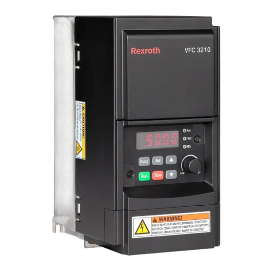
Page 47: Frequency Converter Overview
VFC 3210 Bosch Rexroth AG Frequency Converter Overview 6 Frequency Converter Overview 6.1 Product Features 6.1.1 Input 1P 200...240 VAC (-10 % / +10 %) (IT-Net, TN-Net) Power supply voltage 3P 380...480 VAC (-15 % / +10 %) (IT-Net, TN-Net) Power supply frequency 50 / 60 Hz (±5 %) -
Page 48: Main Functions
Bosch Rexroth AG VFC 3210 Frequency Converter Overview 6.1.4 Main Functions Analog setting: 1/1,000 of maximum frequency Frequency setting resolution Digital setting: 0.01 Hz Analog setting: ±0.1 % of maximum frequency (25 ℃ ± 10 ℃) Frequency setting accuracy Digital setting: ±0.01 % of maximum frequency (-10...50 ℃) -
Page 49: Protection
VFC 3210 Bosch Rexroth AG Frequency Converter Overview 6.1.7 Protection Over current protection, over- / under- voltage protection, surge current / short circuit protection, in- put / output phase loss protection, converter over- / under- temperature protection, motor overload protection, motor over temperature protection, direction lock protection, analog input broken wire de- tection, etc. -
Page 50: Technical Data
Bosch Rexroth AG VFC 3210 Frequency Converter Overview 6.2 Technical Data 6.2.1 Electric Data Motor power 200 V / 240 V 200 V / 240 V Output capacity Model [kW] Input current [A] Output current [A] [kVA] 0K40 6.2 / 5.1 2.4 /2.0... -
Page 51: Derating Of Electric Data
VFC 3210 Bosch Rexroth AG Frequency Converter Overview 6.2.2 Derating of Electric Data Derating and ambient temperature The ambient temperature for Frequency converter VFC 3210 is -10...50 ℃. Out of this range, there will be no possibility to install and run the frequency converter, even the performance data have been additionally reduced. -
Page 52: Derating And Mains Voltage
Bosch Rexroth AG VFC 3210 Frequency Converter Overview Derating and mains voltage Reduce overcurrent based on mains voltage. Frequency converter VFC 3210 is thermally dimensioned for the rated current. This rated current is available with the specified rated voltage. With deviating voltages in the permissible range, please pay attention to the following: <... -
Page 53: Derating And Carrier Frequency
VFC 3210 Bosch Rexroth AG Frequency Converter Overview Derating and carrier frequency In case of higher carrier frequency, the output current is reduced so that the power dissipation in power section remains more or less constant. The figure below shows the current reduction based on the carrier frequency for the fre-... -
Page 54: Frequency Converter Mounting
Bosch Rexroth AG VFC 3210 Frequency Converter Mounting 7 Frequency Converter Mounting 7.1 Installation Conditions To avoid overheating, the device must be ventilated. The recommended mini- mum top and bottom distance between frequency converter and adjacent items (may prevent air flow)are shown as figure below: Fig. -
Page 55: Heat Dissipation
VFC 3210 Bosch Rexroth AG Frequency Converter Mounting 7.2 Heat Dissipation 1P 200 VAC Heat dissipation Frame Model [BTU/h] 0K40 0K75 1K50 2K20 Tab. 7-1: 1P 200 VAC heat dissipation 3P 400 VAC Heat dissipation Frame Model [BTU/h] 0K40 0K75... -
Page 56: Air Flow Of Fans
Bosch Rexroth AG VFC 3210 Frequency Converter Mounting 7.3 Air Flow of Fans 1P 200 VAC Fan for heat sink Fan for internal components Frame Model [CFM] [CFM] /min] /min] 0K40 – – – – 0K75 – – – –... -
Page 57: Figures And Dimensions
VFC 3210 Bosch Rexroth AG Frequency Converter Mounting 7.4 Figures and Dimensions 7.4.1 Figures Fig. 7-2: VFC 3210 0K40...1K50 dimensions figure Fig. 7-3: VFC 3210 2K20...4K00 dimensions figure 29/253 DOK-RCON04-VFC3210****-IT01-EN-P... -
Page 58: Dimensions
Bosch Rexroth AG VFC 3210 Frequency Converter Mounting 7.4.2 Dimensions VFC 3210 Model Dimensions [mm] Screw Frame Ød size weight [kg] ① 0K40 80 135 125 146 4.5 105 2xM4 0.90 0K75 85 145 135 156 4.5 120 2xM4 1.14 1K50 85 185 175 196 4.5 125... -
Page 59: Frequency Converter Wiring
VFC 3210 Bosch Rexroth AG Frequency Converter Wiring 8 Frequency Converter Wiring 8.1 Wiring Diagram Fig. 8-1: Wiring diagram For cable size, fuse, screw torque, see chapter 8.2 "Cable Specifi- ● cations" on page For terminals, see chapter 8.3 "Terminals" on page ●... -
Page 60: Cable Specifications
Bosch Rexroth AG VFC 3210 Frequency Converter Wiring 8.2 Cable Specifications 8.2.1 Power Cables Cable specification for international without USA / Canada ONLY USE copper wires of 90 ℃ or above with XLPE or EPR insu- ● lation according to IEC60364-5-52. -
Page 61: Cable Specification For Usa / Canada
VFC 3210 Bosch Rexroth AG Frequency Converter Wiring Cable specification for USA / Canada The data listed in the table below are only used to select fuse and ● cable dimensions for USA / Canada. ONLY USE copper wires of 75 ℃ or above according to UL 508C. - Page 62 Bosch Rexroth AG VFC 3210 Frequency Converter Wiring Field wiring: Routing of cross sections of terminal connectors wired by the user (in the field). B1 Conductors in installation pipes and Cables or lines on walls in installation channels that can be...
-
Page 63: Control Cables
VFC 3210 Bosch Rexroth AG Frequency Converter Wiring 8.2.2 Control Cables The following requirements are applicable to the signal connection wiring: Flexible cables with wire end sleeves ● Cable cross-section: 0.5...1.0 mm ● Cable cross-section for connectors with insulation sleeves: 0.75 mm ●... -
Page 64: Terminals
Bosch Rexroth AG VFC 3210 Frequency Converter Wiring 8.3 Terminals 8.3.1 Power Terminals Power Terminals Figure Fig. 8-4: Power terminals (1P 200 VAC) Fig. 8-5: Power terminals (3P 400 VAC) Terminal Description L1, L2 Mains supply input terminals U, V, W... -
Page 65: Main Circuit Wiring Step
VFC 3210 Bosch Rexroth AG Frequency Converter Wiring 8.3.2 Main Circuit Wiring Step Fig. 8-6: Main circuit wiring step As the brake resistor is not supported for VFC 3210 to connect, the excessive energy produced in the process of braking can not be eliminated. -
Page 66: Control Terminals
Bosch Rexroth AG VFC 3210 Frequency Converter Wiring 8.3.3 Control Terminals Control terminals figure Fig. 8-7: Control circuit terminals CAUTION The frequency converter might be damaged! Please make sure that the power supply of the frequency converter has been switched off before plugging or unplugging the connector. -
Page 67: Control Terminals Description
VFC 3210 Bosch Rexroth AG Frequency Converter Wiring Control terminals description Digital inputs Terminal Signal function Description Signal requirement Multi-function Inputs via opto-electric couplers: X1...X4 See Group E1 digital inputs 24 VDC, 8 mA / 12 VDC, 4 mA Shared connection for isola-... -
Page 68: Digital Input Npn Wiring
Bosch Rexroth AG VFC 3210 Frequency Converter Wiring Digital outputs Terminal Signal function Description Signal requirement Rated capacity: Relay changeover contacts See Group E2 250 VAC, 3 A; 30 VDC, 3 A Relay shared contact Analog outputs Terminal Signal function... -
Page 69: Analog Input Terminals (Ai, +10 V, Earth And Gnd)
VFC 3210 Bosch Rexroth AG Frequency Converter Wiring Analog input terminals (AI, +10 V, Earth and GND) Fig. 8-9: Analog input terminals Incorrect operation may occur due to interference on the analog sig- nal. In such cases, connect a ferrite magnetic ring at the input side of the analog signal, as shown above. -
Page 70: Relay Output Terminals
Bosch Rexroth AG VFC 3210 Frequency Converter Wiring Relay output terminals When relay output terminals are connected with inductive loads (relays, contac- tors, solenoid valves, motors, etc.), following noise suppression circuits need to be applied at the coils of the inductive loads, as close as possible to the induc- tive loads, in order to reduce the electromagnetic interference generated from inductive load action. -
Page 71: Control Terminals Wiring Step
VFC 3210 Bosch Rexroth AG Frequency Converter Wiring Control terminals wiring step Fig. 8-11: Control terminals wiring step 43/253 DOK-RCON04-VFC3210****-IT01-EN-P... -
Page 72: Electromagnetic Compatibility (Emc)
Bosch Rexroth AG VFC 3210 Electromagnetic Compatibility (EMC) 9 Electromagnetic Compatibility (EMC) 9.1 EMC Requirements 9.1.1 General Information The electromagnetic compatibility (EMC) or electromagnetic interference (EMI) includes the following requirements: Sufficient noise immunity of an electric installation or an electric device ●... -
Page 73: Minimum Immunity Requirements For Pdss Intended For Use In The Second Environment
VFC 3210 Bosch Rexroth AG Electromagnetic Compatibility (EMC) Minimum immunity requirements for PDSs intended for use in the second envi- ronment Basic standard Performance Port Phenomenon for test Level (acceptance method criterion) 4 kV CD or 8 kV AD IEC 61000-4-2 if CD impossible 80...1000 MHz 10 V/m... -
Page 74: Noise Emission Of The Drive System
Bosch Rexroth AG VFC 3210 Electromagnetic Compatibility (EMC) 9.1.3 Noise Emission of the Drive System Causes of noise emission Controlled variable-speed drives contain converters containing snappy semiconductors. The advantage of modifying the speed with high precision is achieved by means of pulse width modulation of the converter voltage. This can generate sinusoidal current with variable amplitude and frequency in the motor. - Page 75 VFC 3210 Bosch Rexroth AG Electromagnetic Compatibility (EMC) Curves of limit IEC / EN In this CISPR 11 Explanation value 61800-3 document characteristic One of the following 3 requirements must have been fulfilled: Mains connection current > 400 A, ●...
- Page 76 Bosch Rexroth AG VFC 3210 Electromagnetic Compatibility (EMC) 1.1 C3 2 3.2 C2 1 environment, QP, I > 100 A (class environment, AV (1 environment, A, group 2, I > 100 A) even if source of interference in 2 1.2 C3 2 environment, AV, I >...
- Page 77 VFC 3210 frequency converter with external EMC filter is applicable to industrial environment (category C3). See the following chapters for the limit classes (as per categories C1, C2, C3, C4 according to EN 61800-3) which can be reached for Bosch Rexroth frequency converter VFC 3210. 49/253...
-
Page 78: Ensuring The Emc Requirements
Bosch Rexroth AG VFC 3210 Electromagnetic Compatibility (EMC) 9.2 Ensuring the EMC Requirements Standards and Laws On the European level there are the EU Directives. In the EU states these Direc- tives are transformed into laws valid on a national level. The relevant directive for EMC is EU Directive 2004/108/EC which was transformed on the national level in Germany into the law EMVG (“Law concerning electromagnetic compati-... - Page 79 VFC 3210 Bosch Rexroth AG Electromagnetic Compatibility (EMC) in the declaration of EMC conformity. This fulfills the legal requirements ac- cording to EMC directive. Case 2: Acceptance test of a machine or installation with the installed drive ● systems. The product standard for the respective type of machine/installation, if exist- ing, applies to the acceptance test of the machine or installation.
-
Page 80: Emc Measures For Design And Installation
Bosch Rexroth AG VFC 3210 Electromagnetic Compatibility (EMC) 9.3 EMC Measures for Design and Installation 9.3.1 Rules for Design of Installations with Drive Controllers in Compli- ance with EMC The following rules are the basics for designing and installing drives in compli-... - Page 81 VFC 3210 Bosch Rexroth AG Electromagnetic Compatibility (EMC) Twisted Wires Twist unshielded wires belonging to the same circuit (feeder and return cable) or keep the surface between feeder and return cable as small as possible. Wires that are not used have to be grounded at both ends.
-
Page 82: Emc-Optimal Installation In Facility And Control Cabinet
Bosch Rexroth AG VFC 3210 Electromagnetic Compatibility (EMC) 9.3.2 EMC-optimal Installation in Facility and Control Cabinet General Information For EMC-optimal installation, a special separation of the interference-free area (mains connection) and the interference-susceptible area (drive components) is recommended, as shown in the figures below. - Page 83 VFC 3210 Bosch Rexroth AG Electromagnetic Compatibility (EMC) even better, via grounding straps with the same cross section. Make sure con- nection points have good contact. 55/253 DOK-RCON04-VFC3210****-IT01-EN-P...
-
Page 84: Control Cabinet Mounting According To Interference Areas - Exem- Plary Arrangements
Bosch Rexroth AG VFC 3210 Electromagnetic Compatibility (EMC) 9.3.3 Control Cabinet Mounting according to Interference Areas – Ex- emplary Arrangements Fig. 9-3: Control cabinet mounting according to interference areas – exemplary arrange- ments 56/253 DOK-RCON04-VFC3210****-IT01-EN-P... -
Page 85: Design And Installation In Area A - Interference-Free Area Of Control Cabinet
VFC 3210 Bosch Rexroth AG Electromagnetic Compatibility (EMC) 9.3.4 Design and Installation in Area A – Interference-free Area of Con- trol Cabinet Arrangement of the Components in the Control Cabinet Comply with a distance of at least 200 mm (distance d1 in the figure): Between components and electric elements (switches, pushbuttons, fuses, ●... - Page 86 Bosch Rexroth AG VFC 3210 Electromagnetic Compatibility (EMC) Routing and Connecting a Neutral Conductor (N) If a neutral conductor is used together with a three-phase connection, it must not be installed unfiltered in areas B and C, in order to keep interference off the mains.
-
Page 87: Design And Installation In Area B - Interference-Susceptible Area Of Control Cabinet
VFC 3210 Bosch Rexroth AG Electromagnetic Compatibility (EMC) Point of Connection for Environment Grounding Conductor at Machine, Installa- tion, Control Cabinet The equipment grounding conductor of the power cable of the machine, installa- tion or control cabinet has to be permanently connected at point PE and have a... -
Page 88: Design And Installation In Area C - Strongly Interference-Susceptible Area Of Control Cabinet
Bosch Rexroth AG VFC 3210 Electromagnetic Compatibility (EMC) 9.3.6 Design and Installation in Area C – Strongly Interference-suscepti- ble Area of Control Cabinet Area C mainly concerns the motor power cables, especially at the connection point of the drive controller. -
Page 89: Ground Connections
VFC 3210 Bosch Rexroth AG Electromagnetic Compatibility (EMC) 9.3.7 Ground Connections Housing and Mounting Plate By means of appropriate ground connections, it is possible to avoid the emis- sion of interference, because interference is discharged to ground on the short- est possible way. -
Page 90: Installing Signal Lines And Signal Cables
Bosch Rexroth AG VFC 3210 Electromagnetic Compatibility (EMC) 9.3.8 Installing Signal Lines and Signal Cables Line Routing The following measures are recommend: Route signal and control lines separately from the power cables with a mini- ● mum distance of d5 = 100 mm (see "Division into Areas (zones)"... -
Page 91: General Measures Of Radio Interference Suppression For Relays, Contactors, Switches, Chokes And Inductive Loads
VFC 3210 Bosch Rexroth AG Electromagnetic Compatibility (EMC) 9.3.9 General Measures of Radio Interference Suppression for Relays, Contactors, Switches, Chokes and Inductive Loads If, in conjunction with electronic devices and components, inductive loads, such as chokes, contactors, relays are switched by contacts or semiconductors, ap- propriate interference suppression has to be provided for them: By arranging free-wheeling diodes in the case of d.c. -
Page 92: Operating Panel And Dust Cover
Bosch Rexroth AG VFC 3210 Operating Panel and Dust Cover 10 Operating Panel and Dust Cover 10.1 LED Panel The LED panel is removable and composed of two areas: display and buttons. The display shows mode settings and operating state of the frequency converter. -
Page 93: Led Indicator
VFC 3210 Bosch Rexroth AG Operating Panel and Dust Cover 10.3 LED Indicator Mode Power off Ready Green / Off Off / Green Run (FWD) Green Green Run (REV) Green Green Run pending Blinks in green DC-braking at start (Short green... -
Page 94: Operating Descriptions
Bosch Rexroth AG VFC 3210 Operating Panel and Dust Cover 10.4 Operating Descriptions Fig. 10-3: Operating mode Fig. 10-4: Operating example 66/253 DOK-RCON04-VFC3210****-IT01-EN-P... -
Page 95: Fast Access To Parameters With Button Combinations
VFC 3210 Bosch Rexroth AG Operating Panel and Dust Cover 10.5 Fast Access to Parameters with Button Combinations VFC 3210 provides fast access to parameters within a parameter group with '<Func> + <▲>' or '<Func> + <▼>' combinations. This function is only valid for the tens digit of the function code index '□□.x□'. -
Page 96: Digit Shifting Function For Modification Of Parameter Values
Bosch Rexroth AG VFC 3210 Operating Panel and Dust Cover 10.6 Digit Shifting Function for Modification of Parameter Values VFC 3210 also provides the digit shifting function for modification of parameter values. To activate this function, press '<Func> + <▲>' or '<Func> + <▼>' once when the frequency converter is displaying a certain parameter value. -
Page 97: Quick Start
VFC 3210 Bosch Rexroth AG Quick Start 11 Quick Start 11.1 Checklist before Quick Start 11.1.1 Step 1: Check application conditions Rated ambient temperature -10...40 ℃ Derating / ambient temperature 1.5 % / 1 °C (40...50 °C) Rated storage temperature -20...60 ℃... -
Page 98: Quick Start Parameters
Bosch Rexroth AG VFC 3210 Quick Start 11.2 Quick Start Parameters Code Name Setting range Default Min. Attri. C0.05 Carrier frequency C1.05 Motor rated power 0.1...1,000.0 kW Stop C1.06 Motor rated voltage 0...480 V Stop C1.07 Motor rated current 0.01...655.00 A 0.01... -
Page 99: Control The Motor
VFC 3210 Bosch Rexroth AG Quick Start 11.3 Control the Motor WARNING Ensure the enclosure is in place before the device is powered on. Wait for at least 5 minutes after powering off to allow the DC capacitor being discharged,... -
Page 100: Motor Parameters Auto-Tuning
Bosch Rexroth AG VFC 3210 Quick Start 11.4 Motor Parameters Auto-Tuning For the applications with higher requirement to control accuracy in V/f control, motor parameter auto-tuning is necessary. Check and make sure the following points before auto-tuning: The motor is in standstill and not at high temperature. -
Page 101: Possible Errors During Quick Start And Respective Solutions
VFC 3210 Bosch Rexroth AG Quick Start 11.5 Possible Errors during Quick Start and Respective Solutions Errors Solutions Over current (SC, OC-1 or OC-2) Increase the acceleration time occurs during acceleration Over voltage (OE-3) Increase the deceleration time occurs during deceleration Over current (SC, OC-1 or OC-2) Incorrect wiring. -
Page 102: Functions And Parameters
Bosch Rexroth AG VFC 3210 Functions and Parameters 12 Functions and Parameters 12.1 Basic Settings 12.1.1 Parameter Group Access Control This function is used to set parameters or read parameter settings fast. Five ac- cess modes are available with parameter b0.00. -
Page 103: Parameter Initialization
VFC 3210 Bosch Rexroth AG Functions and Parameters If a parameter in group '-PF-' is changed back to its default set- ● ting, that parameter is still visible in group '-PF-'. It is invisible af- ter exit from and re-access to group '-PF-'. -
Page 104: Parameter Set Selection
Bosch Rexroth AG VFC 3210 Functions and Parameters 12.1.3 Parameter set selection This function allows to switch between two sets of parameters. It is used if the motors are switched at the output of the frequency converter and two motors should be driven by one device. - Page 105 VFC 3210 Bosch Rexroth AG Functions and Parameters Fig. 12-1: Parameter set selection by b0.12 By digital input: ● Parameter set switch will be carried out with an digital input if one of the pa- rameters E1.00…E1.03 is set to option “46: Parameter set selection”. If one of the digital inputs is configured to option 46 it will override the setting of b0.12 and load the parameter set according to the digital input during power...
-
Page 106: Password Protection
Bosch Rexroth AG VFC 3210 Functions and Parameters 12.1.4 Password Protection Two types of passwords are available, user password and manufacturer pass- word: User password: used to protect parameter settings from unauthorized or un- ● intended changes. Manufacturer password: for service ONLY. -
Page 107: Input And Output Terminals Configuration
VFC 3210 Bosch Rexroth AG Functions and Parameters 12.2 Input and Output Terminals Configuration 12.2.1 Digital Input Configuration 4 multi-function digital inputs are available with PNP and NPN wiring. Code Name Setting range Default Min. Attri. E1.00 X1 input –... - Page 108 Bosch Rexroth AG VFC 3210 Functions and Parameters Used for the 3-wire control mode, see chapter 12.6.3 "2-wire / 3-wire Control (Forward / stop, reverse / stop)" on page 123. 26: Simple PLC stop; 27: Simple PLC pause ● Used for the simple PLC to stop and pause a PLC cycle, see chapter 12.8.4...
-
Page 109: Analog Input Configuration
VFC 3210 Bosch Rexroth AG Functions and Parameters Digital input status is monitored by parameter d0.40 'Digital input 1'. 12.2.2 Analog Input Configuration Please read through the information on 'Wiring diagram' and 'Terminals' before configuration of 'Analog inputs AI', see chapter 8.1 "Wiring Diagram"... - Page 110 Bosch Rexroth AG VFC 3210 Functions and Parameters Fig. 12-3: Curve 1 Analog input status is monitored by parameter d0.30 'AI1 input'. 82/253 DOK-RCON04-VFC3210****-IT01-EN-P...
-
Page 111: Digital Output Configuration
VFC 3210 Bosch Rexroth AG Functions and Parameters 12.2.3 Digital Output Configuration Please read through the information on 'Wiring diagram' and 'Terminals' before configuration of 'Digital output', see chapter 8.1 "Wiring Diagram" on page 31 chapter "Digital outputs" on page 40 respectively. - Page 112 Bosch Rexroth AG VFC 3210 Functions and Parameters 11: Converter overload pre-warning ● chapter "Overload pre-warning" on page 150. 12: Motor overload pre-warning ● chapter "Motor overload pre-warning" on page 158. 13: Converter stop by external error ● chapter 12.10.2 "Reaction to External Error Signals" on page 155.
-
Page 113: Analog Output Configuration
VFC 3210 Bosch Rexroth AG Functions and Parameters 12.2.4 Analog Output Configuration Step 1: Set AO output mode Code Name Setting range Default Min. Attri. E2.26 AO1 output setting 0...12 – AO1 value in percentage E2.28 from extension card 0.00...100.00 % 0.00... - Page 114 Bosch Rexroth AG VFC 3210 Functions and Parameters AO1 output Ref. Reference Fig. 12-4: AO1 output curve Analog output status is monitored by parameter d0.35 'AO1 output'. 86/253 DOK-RCON04-VFC3210****-IT01-EN-P...
-
Page 115: Power Stage Configuration
VFC 3210 Bosch Rexroth AG Functions and Parameters 12.3 Power Stage Configuration 12.3.1 Carrier Frequency Setting Code Name Setting range Default Min. Attri. C0.05 Carrier frequency 2...12 kHz 0: Inactive Carrier frequency auto- C0.06 1: Active – Stop matic adjustment... -
Page 116: Fan Maintenance Reminder
Bosch Rexroth AG VFC 3210 Functions and Parameters 12.3.2 Fan Maintenance Reminder This function is used to remind users maintaining the cooling fan in time. The maintenance time can be set according to the actual application conditions. Code Name Setting range Default Min. -
Page 117: Basic Frequency Setting Sources
VFC 3210 Bosch Rexroth AG Functions and Parameters 12.4 Basic Frequency Setting Sources 12.4.1 Function Description Four means of frequency setting sources are available with priority (0, 1, 2, 3) as shown in the figure below. Only frequency setting source of the fourth priority '3: Basic frequency setting sources' is introduced in this chapter. -
Page 118: Select The Frequency Setting Source
Bosch Rexroth AG VFC 3210 Functions and Parameters 12.4.2 Select the Frequency Setting Source General setting Different frequency setting sources can be selected by setting parameter E0.00 'First frequency setting source' or E0.02 'Second frequency setting source'. Code Name Setting range Default Min. -
Page 119: Frequency Setting Source Switching
VFC 3210 Bosch Rexroth AG Functions and Parameters Frequency setting source switching When [E0.04] = 0, 'Frequency setting source combination' is inactive. The setting frequency can be switched between the first and second frequency setting source by digital input. If status of the selected digital input is changed when frequency converter is... -
Page 120: Frequency Setting Sources Combination
Bosch Rexroth AG VFC 3210 Functions and Parameters Frequency setting sources combination It is possible to combine the two frequency setting sources for complicated ap- plications. First frequency setting source Setting frequency SRC1 Second frequency setting source SRC2 Fig. 12-6: Combination of frequency sources... -
Page 121: Adjust The Setting Frequency By Panel Potentiometer
VFC 3210 Bosch Rexroth AG Functions and Parameters 3: First frequency setting * Second frequency setting ● The actual setting frequency is the result of the multiplication operation of the first and second frequency setting sources. 4: Bigger one of 2 sources ●... -
Page 122: Adjust The Setting Frequency By Panel Button
Bosch Rexroth AG VFC 3210 Functions and Parameters Adjust the setting frequency by panel button The setting frequency of the first and second frequency setting sources can be adjusted by pressing the <▲> / <▼> button on the operating panel. -
Page 123: Adjust The Setting Frequency By Digital Input Up / Down Command
VFC 3210 Bosch Rexroth AG Functions and Parameters Adjust the setting frequency by digital input Up / Down command The setting frequency can also be adjusted with command of Up / Down / Reset, by setting the status of digital inputs. - Page 124 Bosch Rexroth AG VFC 3210 Functions and Parameters Connect switch K2 to X2, and set [E1.01] = '21: Frequency Down command'. Response of setting frequency Closed / Open Closed / Open Closed Is reset to 0.00 Hz Increases from [E1.17] with the...
-
Page 125: Adjust The Setting Frequency By Multi-Speed Function
VFC 3210 Bosch Rexroth AG Functions and Parameters Adjust the setting frequency by multi-speed function Multi-speed function offers flexible, switchable 16 independent stages of setting frequency. The rotation direction of each stage depends on both the 'Stage ac- tion' and the 'Run command source', see the table below:... - Page 126 Bosch Rexroth AG VFC 3210 Functions and Parameters Code Name Setting range Default Min. Attri. E0.07 Digital setting frequency 0.00...[E0.09] Hz 50.00 0.01 E3.40 Multi-speed frequency 1 0.00...[E0.09] Hz 0.00 0.01 E3.41 Multi-speed frequency 2 0.00...[E0.09] Hz 0.00 0.01 E3.42 Multi-speed frequency 3 0.00...[E0.09] Hz...
- Page 127 VFC 3210 Bosch Rexroth AG Functions and Parameters Code Name Setting range Default Min. Attri. E3.18 Acceleration time 6 0.1...6,000.0 s 10.0 E3.19 Deceleration time 6 0.1...6,000.0 s 10.0 E3.20 Acceleration time 7 0.1...6,000.0 s 10.0 E3.21 Deceleration time 7 0.1...6,000.0 s...
- Page 128 Bosch Rexroth AG VFC 3210 Functions and Parameters Fig. 12-10: Multi-speed control via digital inputs Set [E1.15] = 0 or 1 first. Connect switch K1 to X1, and set [E1.00] = '1: Multi-speed control input 1'. Connect switch K2 to X2, and set [E1.01] = '2: Multi-speed control input 2'.
- Page 129 VFC 3210 Bosch Rexroth AG Functions and Parameters ON Digital output active Fig. 12-11: Multi-speed stage transition 101/253 DOK-RCON04-VFC3210****-IT01-EN-P...
-
Page 130: Acceleration And Deceleration Configuration
Bosch Rexroth AG VFC 3210 Functions and Parameters 12.4.3 Acceleration and Deceleration Configuration Acceleration and deceleration time configuration Acceleration / deceleration time setting is the time for frequency increase from 0.00 Hz to [E0.08] 'Maximum output frequency' / the time for frequency de- crease from [E0.08] to 0.00 Hz respectively. -
Page 131: Acceleration And Deceleration Curve Mode Configuration
VFC 3210 Bosch Rexroth AG Functions and Parameters Code Name Setting range Default Min. Attri. E3.21 Deceleration time 7 0.1...6,000.0 s 10.0 E3.22 Acceleration time 8 0.1...6,000.0 s 10.0 E3.23 Deceleration time 8 0.1...6,000.0 s 10.0 E1.00 X1 input 10: Acceleration / deceleration time 1 –... - Page 132 Bosch Rexroth AG VFC 3210 Functions and Parameters Fig. 12-13: Linear mode acceleration and deceleration [E0.25] = 1: S-curve ● ① ④ [E0.28] Acceleration starting phase [E0.28] Deceleration starting phase ③ ⑥ [E0.29] Acceleration stopping phase [E0.29] Deceleration stopping phase Fig.
-
Page 133: Output Frequency Limitation
VFC 3210 Bosch Rexroth AG Functions and Parameters 12.4.4 Output Frequency Limitation Direct output frequency limitation Code Name Setting range Default Min. Attri. E0.08 Maximum output frequency 50.00...400.00 Hz 50.00 0.01 Stop E0.09 Output frequency high limit [E0.10]...[E0.08] Hz 50.00 0.01... -
Page 134: Frequency Setting Saving
Bosch Rexroth AG VFC 3210 Functions and Parameters For applications, in which the running frequency cannot be too low, define the low limit frequency running mode when the output frequency is lower than [E0.10] 'Output frequency low limit'. [E0.15] = 1: Run with low limit frequency ●... -
Page 135: Run- / Stop- / Direction Command Source
VFC 3210 Bosch Rexroth AG Functions and Parameters 12.5 Run- / Stop- / Direction Command Source 12.5.1 Function Description The Run- / Stop- / Direction Command can be configured by the following means: First priority: PID control ● Second priority: Simple PLC ●... -
Page 136: Run Command Source
Bosch Rexroth AG VFC 3210 Functions and Parameters 12.5.2 Run Command Source First and second run command source configuration Code Name Setting range Default Min. Attri. E0.01 First run command source 0...2 – Stop E0.03 Second run command source 0...2 –... -
Page 137: Direction Control
VFC 3210 Bosch Rexroth AG Functions and Parameters 12.5.3 Direction Control Direction control via operation panel The actual direction is controlled by the configuration of parameter [U0.00] 'Di- rection control by panel' and [E0.17] 'Direction control'. Code Name Setting range Default Min. -
Page 138: Direction Change Dead Time
Bosch Rexroth AG VFC 3210 Functions and Parameters Direction change dead time A dead time exists if the direction is changed from forward / reverse to reverse / forward, which can be defined according to actual application. Code Name Setting range Default Min. -
Page 139: Start Behavior Setting
VFC 3210 Bosch Rexroth AG Functions and Parameters 12.5.4 Start Behavior Setting Start mode selection Code Name Setting range Default Min. Attri. 0: Start directly 1: DC-braking before start E0.35 Start mode – Stop 2: Start with speed capture 3: Automatic start / stop accord-... -
Page 140: Dc-Braking Before Start
Bosch Rexroth AG VFC 3210 Functions and Parameters DC-braking before start DC-braking is used in applications, in which regular deceleration to stop or a quick stop is required. The larger DC-braking current, the larger braking force. However, the withstanding capability of the mo- tor has to be considered before use the DC-braking function. -
Page 141: Start With Speed Capture
VFC 3210 Bosch Rexroth AG Functions and Parameters Start with speed capture This mode is used after transient power fault in applications with a large inertia load. The frequency converter firstly identifies the rotation speed and direction of the motor, and then starts with the current frequency of the motor to realize smooth starting without shock to the rotating motor. -
Page 142: Automatic Start / Stop According To Setting Frequency
Bosch Rexroth AG VFC 3210 Functions and Parameters Automatic start / stop according to setting frequency With this function, the converter starts when the setting frequency from analog input is higher than the threshold, and stops when the setting frequency from analog input is lower than the threshold. - Page 143 VFC 3210 Bosch Rexroth AG Functions and Parameters – Pressing <Stop> at this time, the frequency converter stops. – Pressing <Run> again, the frequency converter runs again. When using this function, press <Run> firstly before setting the ana- log input.
-
Page 144: Stop Behavior Setting
Bosch Rexroth AG VFC 3210 Functions and Parameters 12.5.5 Stop Behavior Setting Stop mode setting Code Name Setting range Default Min. Attri. E0.50 Stop mode 0...2 – Stop E1.00 X1 input – Stop E1.01 X2 input – Stop 15: Freewheeling stop activation E1.02 X3 input... -
Page 145: Dc-Braking During Deceleration To Stop
VFC 3210 Bosch Rexroth AG Functions and Parameters DC-braking during deceleration to stop Code Name Setting range Default Min. Attri. E0.50 Stop mode 0: Decelerating stop – Stop Stop DC-braking frequency E0.52 0.00...50.00 Hz 0.00 0.01 Stop threshold E0.53 Stop DC-braking time 0.0...20.0 s (0.0: Inactive) - Page 146 Bosch Rexroth AG VFC 3210 Functions and Parameters Fig. 12-23: Stop DC-braking 118/253 DOK-RCON04-VFC3210****-IT01-EN-P...
-
Page 147: Overexcitation Braking
VFC 3210 Bosch Rexroth AG Functions and Parameters Overexcitation braking This function is used to obtain an optimized braking performance of the fre- quency converter in V/f control mode. To realize this function, increase 'Convert- er output voltage' by fine tuning of parameter E0.55 'Overexcitation braking fac- tor' during deceleration process. -
Page 148: Special Running Behaviors
Bosch Rexroth AG VFC 3210 Functions and Parameters 12.6 Special Running Behaviors 12.6.1 Skip Frequency This function is used to avoid the mechanical resonance of the motor by defini- tion of skip frequencies. Code Name Setting range Default Min. Attri. -
Page 149: Jog Function
VFC 3210 Bosch Rexroth AG Functions and Parameters Parameter E0.74 is used to control the acceleration / deceleration speed inside the skip-window, the range for this factor is 1 (normal speed) to 100 (100 times speed of the normal speed). - Page 150 Bosch Rexroth AG VFC 3210 Functions and Parameters – 'Jog command' active: Accelerate to [E0.60] 'Jog frequency' according to [E0.61] 'Jog acceleration time'. – 'Jog command' inactive: Decelerate to prior 'Setting frequency' accord- ing to [E0.27] 'Deceleration time'. Fig. 12-25: Jog acceleration / deceleration time...
-
Page 151: 2-Wire / 3-Wire Control (Forward / Stop, Reverse / Stop)
VFC 3210 Bosch Rexroth AG Functions and Parameters 12.6.3 2-wire / 3-wire Control (Forward / stop, reverse / stop) 2-wire control mode 1 Step 1: Activate 2-wire control mode 1 Set [E1.15] = '0: Forward / stop, reverse / stop'. -
Page 152: 2-Wire Control Mode 2 (Forward / Reverse, Run / Stop)
Bosch Rexroth AG VFC 3210 Functions and Parameters 2-wire control mode 2 (Forward / reverse, run / stop) Step 1: Activate 2-wire control mode 2 Set [E1.15] = '1: Forward / reverse, run / stop'. Step 2: Define two digital inputs Set one of digital inputs as '35: Forward running (FWD)' ●... -
Page 153: 3-Wire Control Mode 1
VFC 3210 Bosch Rexroth AG Functions and Parameters 3-wire control mode 1 Step 1: Define 3 digital inputs Set one of digital inputs as '35: Forward running (FWD)' ● Set one of digital inputs as '36: Reverse running (REV)' ●... -
Page 154: 3-Wire Control Mode 2
Bosch Rexroth AG VFC 3210 Functions and Parameters 3-wire control mode 2 Different from the 3-wire control mode 1, 3-wire control mode 2 has a edge sen- sitive characteristic for direction control terminals. Step 1: Define 3 digital inputs Set one of digital inputs as '35: Forward running (FWD)' ●... -
Page 155: Special Functions
VFC 3210 Bosch Rexroth AG Functions and Parameters 12.7 Special Functions 12.7.1 Counter Function The internal counter counts the input pulses received from 'digital input' and compares it with the setting value of 'Counter middle value' or 'Counter target value'. - Page 156 Bosch Rexroth AG VFC 3210 Functions and Parameters Running status Status Inactive Inactive – – Counter value Internal counter value stays at [E2.80] / [E2.81] Edge Inactive = [E2.80] / [E2.81] Digital output is active Internal counter value is reset to ‘0’...
-
Page 157: Frequency Arrival
VFC 3210 Bosch Rexroth AG Functions and Parameters 12.7.2 Frequency Arrival This function is used to detect the difference between the output frequency and the setting frequency. When the difference is within the frequency detection width, an indication signal will be generated for further engineering in the appli- cation. -
Page 158: Frequency Level Detection
Bosch Rexroth AG VFC 3210 Functions and Parameters 12.7.3 Frequency Level Detection This function is used to detect the difference between the output frequency and the setting frequency. An indication signal will be generated ONLY when the out- put frequency is HIGHER than the lower limit of the frequency detection level. -
Page 159: High Resolution Current Display
VFC 3210 Bosch Rexroth AG Functions and Parameters 12.7.4 High Resolution Current Display Code Name Setting range Default Min. Attri. E5.01 High resolution output current filter time 5...500 ms d0.98 High resolution output current – – 0.01 Read E5.01 is used to set the time constant of dynamic output current in applications where a high resolution value with two decimals are required for monitoring or control. -
Page 160: Simple Plc
Bosch Rexroth AG VFC 3210 Functions and Parameters 12.8 Simple PLC 12.8.1 Function Description Simple PLC is an automatic running mode based on the current acceleration / deceleration time, setting frequency, duration and rotation direction. Simple PLC consists of 16 stages, each of which has its own settings of acceler- ation time, deceleration time, setting frequency, rotation direction and duration. -
Page 161: Set The Simple Plc Mode
VFC 3210 Bosch Rexroth AG Functions and Parameters 12.8.2 Set the Simple PLC Mode Code Name Setting range Default Min. Attri. E3.00 Simple PLC running mode 0...3 – Stop E3.01 Simple PLC time multiplier 1...60 Stop E3.02 Simple PLC cycle number 1...1,000... -
Page 162: Set Speed / Direction / Acceleration And Deceleration Time
Bosch Rexroth AG VFC 3210 Functions and Parameters 12.8.3 Set Speed / Direction / Acceleration and Deceleration Time Code Name Setting range Default Min. Attri. E0.07 Digital setting frequency 0.00...[E0.09] Hz 50.00 0.01 E3.40 Multi-speed frequency 1 0.00...[E0.09] Hz 0.00 0.01... - Page 163 VFC 3210 Bosch Rexroth AG Functions and Parameters Code Name Setting range Default Min. Attri. E3.12 Acceleration time 3 0.1...6,000.0 s 10.0 E3.13 Deceleration time 3 0.1...6,000.0 s 10.0 E3.14 Acceleration time 4 0.1...6,000.0 s 10.0 E3.15 Deceleration time 4 0.1...6,000.0 s...
-
Page 164: Stop And Pause Simple Plc Control
Bosch Rexroth AG VFC 3210 Functions and Parameters 12.8.4 Stop and Pause Simple PLC Control Active 'Simple PLC control' can be stopped or paused by configuration of digital inputs with functions of 'Simple PLC stop' or 'Simple PLC pause'. Code... -
Page 165: Indication Of Simple Plc Status
VFC 3210 Bosch Rexroth AG Functions and Parameters 12.8.5 Indication of Simple PLC Status An indication signal is active via 'DO1 output' or 'Relay 1 output' when a simple PLC cycle or stage is complete. Define the output with respective indication signals as below:... - Page 166 Bosch Rexroth AG VFC 3210 Functions and Parameters Fig. 12-36: Simple PLC cycle complete When a cycle is complete, a pulse signal is active for the duration of 0.5 s. 138/253 DOK-RCON04-VFC3210****-IT01-EN-P...
-
Page 167: Pid Control
VFC 3210 Bosch Rexroth AG Functions and Parameters 12.9 PID Control 12.9.1 Function Description PID control is used in process controls such as flow control, pressure control, temperature control, and in control of other engineering values. In PID control, a... -
Page 168: Selecting The Reference And Feedback
Bosch Rexroth AG VFC 3210 Functions and Parameters 12.9.2 Selecting the Reference and Feedback Before using PID control function make sure [E1.00]…[E1.04] ≠ '41: PID deacti- vation'. Take the following steps to configure the PID reference: Step 1: Select the PID reference channel... -
Page 169: Control Loop Configuration
VFC 3210 Bosch Rexroth AG Functions and Parameters 12.9.3 Control Loop Configuration Code Name Setting range Default Min. Attri. E4.15 Proportional gain - P 0.000...60.000 1.500 0.001 0.00...100.00 s E4.16 Integral time - Ti 1.50 0.01 (0.00: no integral) 0.00...100.00 s E4.17 Derivative time - Td... -
Page 170: Pid Regulation Mode Setting
Bosch Rexroth AG VFC 3210 Functions and Parameters 12.9.4 PID Regulation Mode Setting Code Name Setting range Default Min. Attri. E4.30 PID deadband 0.0...20.0 % This parameter is used to set the limit of the deviation between reference and feedback value. When the difference is within the defined 'PID deadband', PID control stops to bring a stable output. -
Page 171: Pid Feedforward Control
VFC 3210 Bosch Rexroth AG Functions and Parameters 12.9.5 PID Feedforward Control Code Name Setting range Default Min. Attri. PID feed forward dynamic E4.19 0.00...100.00 % 10.00 0.01 limit E4.20 PID feed forward limit offset 0.00...100.00 % 2.00 0.01 E4.33 PID feedforward settings 0: Inactive;... -
Page 172: Pid Deactivation By Digital Input
Bosch Rexroth AG VFC 3210 Functions and Parameters 12.9.6 PID Deactivation by Digital Input Fig. 12-39: PID deactivation by digital input The PID control is deactivated in the following ways: 'PID reference channel' [E4.00] = '0: No PID control' or ●... -
Page 173: Pid Status Indication
VFC 3210 Bosch Rexroth AG Functions and Parameters 12.9.8 PID Status Indication Code Name Setting range Default Min. Attri. E4.32 PID engineering value detection width 0.01...100.00 1.00 0.01 18: PID reference engi- E2.15 Relay 1 output selection – Stop neering value arrival [E4.32] 'PID engineering value detection width' is used to set the tolerance win-... -
Page 174: Sleep / Wake Function
Bosch Rexroth AG VFC 3210 Functions and Parameters 12.9.9 Sleep / Wake Function This function is used to achieve the maximum extent of energy-saving according to type of loads in actual applications. Code Name Setting range Default Min. Attri. E5.15 Sleep level 0.00...[E0.09] Hz... - Page 175 VFC 3210 Bosch Rexroth AG Functions and Parameters Fig. 12-41: Sleep and wake up process After [E5.16] 'Sleep delay', the PID controller boosts up with [E5.18] 'Sleep boost amplitude' within [E5.17] 'Sleep boost time', and then enters to sleep mode. In sleep mode, the frequency converter stops output with 'PSLP' dis- played on the operating panel.
-
Page 176: Pump Protection Function
Bosch Rexroth AG VFC 3210 Functions and Parameters 12.9.10 Pump Protection Function Two modes of pump protection are available: Pump dry protection: Protecting the pump from running without water load ● (e.g., water pump without water) Pump leakage protection: Protecting the pump from running with leakage ●... - Page 177 VFC 3210 Bosch Rexroth AG Functions and Parameters The 'Pump dry protection delay at start-up' E5.07 and the 'Pump ● leakage protection delay at start-up' E5.10 are used to prevent the two modes of protection at start-up process. These two modes of protection are only valid when PID control is ●...
-
Page 178: Protection Functions
Bosch Rexroth AG VFC 3210 Functions and Parameters 12.10 Protection Functions 12.10.1 Converter Protection Overload pre-warning When the frequency converter output current is higher than [C0.29] 'Converter overload pre-warning level' and lasts for longer than [C0.30] 'Converter overload pre-warning delay', the 'Converter overload pre-warning' signal will be active on the selected digital output terminal. -
Page 179: Stall Overvoltage Prevention
VFC 3210 Bosch Rexroth AG Functions and Parameters Stall overvoltage prevention This function is used to prevent the frequency converter from overvoltage during deceleration when the load is excessively heavy or the deceleration time is ex- cessively short. Code Name... -
Page 180: Stall Overcurrent Prevention
Bosch Rexroth AG VFC 3210 Functions and Parameters Stall overcurrent prevention This function is used to prevent the frequency converter from overcurrent when the load is excessively heavy or the acceleration time is excessively short. This function is always active during acceleration or at constant speed. - Page 181 VFC 3210 Bosch Rexroth AG Functions and Parameters Fig. 12-44: Stall overcurrent at constant speed [Output current] > [C0.27] ● The output frequency decreases till the output current is lower than [C0.27] with defined deceleration time. [Output current] < [C0.27] ●...
-
Page 182: Phase Loss Protection
Bosch Rexroth AG VFC 3210 Functions and Parameters Phase loss protection Error code 'IPH.L' is displayed on the operating panel in case of input phase loss error occurs; error code 'OPH.L' is displayed on the operating panel in case of output phase loss error occurs. -
Page 183: Reaction To External Error Signals
VFC 3210 Bosch Rexroth AG Functions and Parameters 12.10.2 Reaction to External Error Signals The frequency converter stops once an external error signal is active and the error code 'E-St' will be displayed on the operating panel if one X1...X4 input is defined as either 'Error signal N.O. - Page 184 Bosch Rexroth AG VFC 3210 Functions and Parameters The frequency converter stops and indicates error code 'E-St' if K1 is closed. The frequency converter stops and indicates error code 'E-St' if K2 is open. 156/253 DOK-RCON04-VFC3210****-IT01-EN-P...
-
Page 185: Motor Protection
VFC 3210 Bosch Rexroth AG Functions and Parameters 12.10.3 Motor Protection Motor derating frequency at low speed This function is used to reduce the overload and thermal risks as motors have worse cooling performance at low speed, compared at rated speed. -
Page 186: Motor Thermal Protection Without Temperature Sensor
Bosch Rexroth AG VFC 3210 Functions and Parameters Motor thermal protection without temperature sensor This function is to realize the motor thermal protection based on the thermal model of motor. Code Name Setting range Default Min. Attri. 0: Inactive C1.69 Motor thermal model protection setting –... -
Page 187: Motor Thermal Protection With Temperature Sensor
VFC 3210 Bosch Rexroth AG Functions and Parameters Motor thermal protection with temperature sensor For a temperature sensor with voltage supply, use terminals +10 V, AI and GND on the frequency converter. Fig. 12-48: Temperature sensor with voltage supply For a temperature sensor with current supply, use terminals AO, AI and GND on the frequency converter. - Page 188 Bosch Rexroth AG VFC 3210 Functions and Parameters Code Name Setting range Default Min. Attri. 0: Output frequency 1: Setting frequency 2: Output current 4: Output voltage E2.26 AO1 output setting – 5: Output power 6: AI1 analog input 12: Parameter setting...
-
Page 189: Power Loss Ride-Through Mode
VFC 3210 Bosch Rexroth AG Functions and Parameters If the input terminals are occupied by other functions, E1.60 cannot be set to 1. 12.10.4 Power loss ride-through mode Code Name Setting range Default Min. Attri. 0: Inactive 1: Output disabled C0.40... -
Page 190: Motor Control
Bosch Rexroth AG VFC 3210 Functions and Parameters 12.11 Motor Control 12.11.1 Expert mode Code Name Setting range Default Min. Attri. 0: Standard mode C1.02 Expert mode Stop 1: Expert mode 0: Every change of a motor parameter leads to a recalculation based on the as- cending rule. -
Page 191: Motor Parameter Auto-Tuning
VFC 3210 Bosch Rexroth AG Functions and Parameters Fig. 12-50: Slip frequency compensation If the slip frequency compensation is excessively large, the motor speed may exceed the synchronous speed. Code Name Setting range Default Min. Attri. C1.12 Motor rated slip frequency 0.00...60.00 Hz... - Page 192 Bosch Rexroth AG VFC 3210 Functions and Parameters Code Name Setting range Default Min. Attri. C1.23 Leakage inductance 0.00...200.00 mH 0.01 Stop C1.24 Mutual inductance 0.0...3,000.0 mH Stop For the applications with higher performance requirement in V/f control, motor parameter auto-tuning is necessary.
- Page 193 VFC 3210 Bosch Rexroth AG Functions and Parameters For example, if by applying the parameter auto-tuning function, the user goes first to set the parameters of physical parameter level and control parameter lev- el, and next execute the modify to the parameters of top level or nameplate lev- el.
-
Page 194: V/F Control
Bosch Rexroth AG VFC 3210 Functions and Parameters 12.11.3 V/f Control V/f curve selection Code Name Setting range Default Min. Attri. C2.00 V/f curve mode 0...2 – Stop The frequency converter provides three curve modes: 0: Linear ● This mode refers to linear voltage / frequency control, which is used for nor- mal constant torque loads. -
Page 195: User-Defined V/F Curve Configuration
VFC 3210 Bosch Rexroth AG Functions and Parameters This mode refers to voltage / frequency control with curve defined according to actual application, which is used for special loads of dewatering machines, centrifuges, etc. Fig. 12-53: User-defined V/f curve 3: V/f separation ●... - Page 196 Bosch Rexroth AG VFC 3210 Functions and Parameters User-defined V/f curve when [C2.05] ≤ [C1.08] ● In this mode, the output voltage is limited to 100 % even if [C2.06] 'V/f volt- age 3' is higher than 100 %. Fig. 12-54: User-defined V/f curve when [C2.05] ≤ [C1.08] User-defined V/f curve when [C2.05] ≥...
-
Page 197: Slip Compensation Factor Configuration
VFC 3210 Bosch Rexroth AG Functions and Parameters Fig. 12-55: User-defined V/f curve when [C2.05] ≥ [C1.08] Slip compensation factor configuration This function is used to compensate [C1.12] 'Motor rated slip compensation' ac- cording to the actual applications in V/f control. -
Page 198: Torque Boost Setting
Bosch Rexroth AG VFC 3210 Functions and Parameters Torque boost setting The torque boost function is used to obtain higher output torque and better sta- bilization by boosting the output voltage, especially at low speed. Code Name Setting range Default Min. - Page 199 VFC 3210 Bosch Rexroth AG Functions and Parameters Fig. 12-57: Manual torque boost with square curve In automatic boost mode, the output voltage boost percentage is determined au- tomatically by the output frequency and the load current. The linear and square V/f curves for automatic torque boost are shown as figures below.
- Page 200 Bosch Rexroth AG VFC 3210 Functions and Parameters Fig. 12-59: Automatic torque boot with square V/f curve For further adjustment of the voltage boost, set parameter C2.22 'Automatic tor- que boost factor'. Its default value 50 % means no adjustment. The calculation equation is shown as below: [Voltage boost] = √3 x 0.5 x I...
-
Page 201: Optimization Functions For V/F Control
VFC 3210 Bosch Rexroth AG Functions and Parameters Optimization functions for V/f control Zero speed control selection Code Name Setting range Default Min. Attri. 0: No output C2.20 0 Hz output mode Stop 1: Standard C2.20=0: No any torque output in this mode. - Page 202 Bosch Rexroth AG VFC 3210 Functions and Parameters Output current limitation This function is used to avoid the tripping caused by over current when the load has large inertia or sudden changes. Code Name Setting range Default Min. Attri. C2.40 Current limitation mode 0...2...
-
Page 203: Diagnosis
VFC 3210 Bosch Rexroth AG Diagnosis 13 Diagnosis 13.1 Display of LED Characters Character Display Character – Display – Tab. 13-1: Display of LED characters 13.2 Status Code Code Description 8.8.8.8.8. Displayed at power on, detecting the operating panel '-' '--' '---' '----' '-----' During parameter backup…... -
Page 204: Error Code
Bosch Rexroth AG VFC 3210 Diagnosis 13.4 Error Code 13.4.1 Error 1 (OC-1): Overcurrent at Constant Speed Possible reason Solution Sudden load change in run mode Reduce occurrence and scale of sudden change Low mains voltage Check input power supply... -
Page 205: Error 4 (Oe-1): Overvoltage At Constant Speed
VFC 3210 Bosch Rexroth AG Diagnosis Possible reason Solution Excessive overexcitation braking factor Reduce [E0.55] Wrong motor parameter setting Correct motor parameters setting 13.4.4 Error 4 (OE-1): Overvoltage at Constant Speed Possible reason Solution Surge voltage from power supply Check input power supply... -
Page 206: Error 7 (Oe-4): Overvoltage During Stop
Bosch Rexroth AG VFC 3210 Diagnosis 13.4.7 Error 7 (OE-4): Overvoltage during Stop Possible reason Solution ● Increase deceleration time (E0.27) Excessive inertia on the load ● Use suitable brake components Surge voltage from the power supply Check input power supply 13.4.8 Error 8 (UE-1): Undervoltage during Run... -
Page 207: Error 12 (Ess-): Soft Start Error
VFC 3210 Bosch Rexroth AG Diagnosis 13.4.12 Error 12 (ESS-): Soft Start Error Possible reason Solution Soft start resistor value has been changed Contact with service due to over temperature Power failure Check the input power supply Input phase loss occurs during start-up (3... -
Page 208: Error 23 (Ff): Fan Failure
Bosch Rexroth AG VFC 3210 Diagnosis 13.4.15 Error 23 (FF): Fan Failure Possible reason Solution Fan defect Contact with service 13.4.16 Error 24 (Pdr): Pump Dry Possible reason Solution ● Check if the feedback signal is valid PID feedback is excessively low while con- verter is running at output frequency high ●... -
Page 209: Error 31 (Ot): Motor Over Temperature
VFC 3210 Bosch Rexroth AG Diagnosis 13.4.19 Error 31 (Ot): Motor over Temperature Possible reason Solution ● Check load Excessive load or bad cooling ● Provide a better cooling condition Temperature sensor defect Check the motor temperature sensor feedback signal... -
Page 210: Error 41 (Dir2): Reverse Running Lock Error
Bosch Rexroth AG VFC 3210 Diagnosis 13.4.24 Error 41 (dir2): Reverse Running Lock Error Possible reason Solution Direction control [E0.17] = '2: Reverse only' Correct the parameter setting Direction command is forward 13.4.25 Error 42 (E-St): Terminal Error Signal Possible reason... -
Page 211: Error 45 (E.par): Parameter Settings Invalid
VFC 3210 Bosch Rexroth AG Diagnosis 13.4.28 Error 45 (E.Par): Parameter Settings Invalid Possible reason Solution 1. Check parameter group '-EP-' and modify the parameter values appeared Parameter settings are invalid after firmware update or in '-EP-' extension card removed or parameter copy 2. -
Page 212: Error Handling
Bosch Rexroth AG VFC 3210 Diagnosis 13.5 Error Handling 13.5.1 Restarting after Power Loss Code Name Setting range Default Min. Attri. 0: Inactive E0.45 Power loss restart mode 1: Active for panel control – Stop 2: Active only for 2-wire control E0.46 Power loss restart delay... -
Page 213: Automatic Error Reset
VFC 3210 Bosch Rexroth AG Diagnosis 13.5.2 Automatic Error Reset Automatic error reset function is used to ensure continuous running without hu- man intervention in the case of occasional errors, such as overcurrent or over- voltage at start or in the run mode. This function can be activated by setting [E9.00] ≠... - Page 214 Bosch Rexroth AG VFC 3210 Diagnosis Code Name Setting range Default Min. Attri. E1.00 X1 input – Stop E1.01 X2 input – Stop 34: Error reset E1.02 X3 input – Stop E1.03 X4 input – Stop Set the respective parameter of any digital input as '34: Error reset'. For wiring diagram, please refer to chapter "Digital input NPN wiring"...
-
Page 215: Communication
VFC 3210 Bosch Rexroth AG Communication 14 Communication 14.1 Brief Introduction VFC 3210 frequency converters provide standard RS485 communication inter- face to realize the communication between the master and slaves via Modbus protocol. With the help of a PC, a PLC or an external computer a 'single master /... -
Page 216: Setting The Data Format
Bosch Rexroth AG VFC 3210 Communication 14.2.2 Setting the Data Format Code Name Setting range Default Min. Attri. E8.11 Modbus data format 0...3 – Stop 0: 1 start bit, 8 data bits, 1 stop bit, no parity ● 1: 1 start bit, 8 data bits, 1 stop bit, even parity ●... -
Page 217: Communication Disruption And Response
VFC 3210 Bosch Rexroth AG Communication 14.2.5 Communication Disruption and Response Code Name Setting range Default Min. Attri. Communication error E8.01 0.0...60.0 s (0.0: Inactive) Stop detection time Communication error E8.02 0, 1, 2 – Stop protection mode When [E8.01] = 0.0 s, the disruption detection function is inactive. -
Page 218: Modbus Protocol
Bosch Rexroth AG VFC 3210 Communication 14.3 Modbus Protocol 14.3.1 Protocol Description Brief introduction Modbus is a master / slave protocol. Only one device may send commands in ● the network at a particular time. The master station manages message exchange by polling the slave stations. -
Page 219: Transmission
VFC 3210 Bosch Rexroth AG Communication Transmission The transmission is of RTU (Remote Terminal Unit) mode with frames containing no message header or end mark. A typical RTU frame format is shown below: Slave address Function code Data 1 byte 1 byte 0...252 byte(s) -
Page 220: Modbus Interface
Bosch Rexroth AG VFC 3210 Communication 14.3.2 Modbus Interface The Modbus communication is via RS485 interface, see descriptions on RS485+ and RS485- in chapter 8.1 "Wiring Diagram" on page 31 chapter 8.3 "Termi- nals" on page 14.3.3 Modbus Function and Message Format Supported functions The main function of Modbus is to read and to write parameters. - Page 221 VFC 3210 Bosch Rexroth AG Communication Slave Test word 1 Test word 2 CRC16 0x08 Hi | Lo Hi | Lo Lo | Hi Tab. 14-7: Function 8_Master request and slave response (in same format) Address of Number Number Last word...
-
Page 222: Function Example
Bosch Rexroth AG VFC 3210 Communication Function example Function 0x03: Read N register words, range: 1...16 Example: It is necessary to read 2 continuous words starting from communica- tion register 3000H of the slave frequency converter addressed at 01H. The frame structure is described in the tables below. -
Page 223: Function 0X06: Write One Register Word
VFC 3210 Bosch Rexroth AG Communication Function 0x06: Write one register word CAUTION Frequent writing may damage the internal registers! When data is written into the internal registers, there is a limit on the writing ● times. The register address may be damaged once the writing times is beyond the writing limit. -
Page 224: Function 0X08: Diagnostics
Bosch Rexroth AG VFC 3210 Communication Function 0x08: Diagnostics Example: To test the communication loop of 2 continuous words 1234H and 5678H with frequency converter slave address 01H, the frame structure is de- scribed in the tables below: Message start Transmission time for 3.5 bytes... -
Page 225: Function 0X10: Write N Register Words, Range: 1
VFC 3210 Bosch Rexroth AG Communication Function 0x10: Write N register words, range: 1...16 Example: To modify 2 continuous registers start from 4000H with words 0001H and 0000H with slave frequency converter address 01H. The frame structure is described in the tables below: Message start Transmission time for 3.5 bytes... - Page 226 Bosch Rexroth AG VFC 3210 Communication Message start Transmission time for 3.5 bytes Slave address Modbus function code Higher byte of read register start address Lower byte of read register start address Higher byte of read register number Lower byte of read register number...
-
Page 227: Error Code And Exception Code
VFC 3210 Bosch Rexroth AG Communication Error code and exception code If a slave receives the request without a communication error, but cannot handle it, the slave will return an exception response which includes error code and ex- ception code informing the master of the nature of the error. The error code is formed by setting the MSB of the function code to 1 (i.e. -
Page 228: Communication Mapping Register Address Distribution
Bosch Rexroth AG VFC 3210 Communication 14.3.4 Communication Mapping Register Address Distribution Frequency converter parameter address Frequency converter parameter registers correspond to the function codes one- to-one. Reading and writing of related function codes can be achieved through reading and writing of the contents in frequency converter parameter registers via Modbus communication. -
Page 229: Communication Control Register (0X7F00)
VFC 3210 Bosch Rexroth AG Communication Communication control register (0x7F00) The address of command word register for communication control is 0x7F00. This register is write-only. The frequency converter is controlled through writing data into the address. The definition of each bit is shown in table below:... -
Page 230: Communication State Register (0X7Fa0)
Bosch Rexroth AG VFC 3210 Communication Communication state register (0x7FA0) The frequency converter state can be monitored by reading the register. This register is read-only. The definition of each bit is shown in the table below: Value Description 15 ... 8 –... -
Page 231: Additional Status Register (0X7Fa1)
VFC 3210 Bosch Rexroth AG Communication Additional status register (0x7FA1) Additional status register is the extension of main status register(7FA0H), it stores other status information of frequency converter. This register is read-only. The definition of each bit is shown in the table below:... -
Page 232: Fault Status Register (0X7Fb0)
Bosch Rexroth AG VFC 3210 Communication Fault status register (0x7FB0) The fault status of frequency converter can be monitored by reading the register. This register is read-only. Description No error OC-1, overcurrent at constant speed OC-2, overcurrent during acceleration OC-3, overcurrent during deceleration... -
Page 233: Communication Frequency Setting Register (0X7F01)
VFC 3210 Bosch Rexroth AG Communication Description E-St, terminal error signal FFE-, firmware version mismatch rS-, modbus communication error E.Par, parameter settings invalid U.Par, unknown parameter restore error idA-, internal communication error idP-, internal parameter error IDE-, converter internal error... -
Page 234: Modbus Communication Example
Bosch Rexroth AG VFC 3210 Communication 14.3.5 Modbus Communication Example One slave address is 01H. The frequency setting of the frequency converter has been set to 'Given by communication' and the RUN command source is set to 'In- putting commands by communication'. It is required for the motor connected to the frequency converter to run with 50 Hz (forward rotation). -
Page 235: Special Notes
VFC 3210 Bosch Rexroth AG Communication 14.3.6 Special Notes 1. The external computer can not write to function codes b0.11 'Parameter copy', U1.00 'running monitoring display' and U1.10 'Stop monitoring dis- play'. 2. b0.20 'User password' and b0.10 'Parameter initialization' do not support multiple write including single write in multiple write;... -
Page 236: Communication Networking
Bosch Rexroth AG VFC 3210 Communication 14.3.7 Communication Networking Networking The communication network is shown in figure below, with a PC, a PLC or an ex- ternal computer as the master and all frequency converters as slaves, which are connected by shielded twisted pair cables. The slave at the end of the network needs a termination resistor with recommended value of 120 Ω, 0.25 W. -
Page 237: Accessories
VFC 3210 Bosch Rexroth AG Accessories 15 Accessories 15.1 Optional Accessories Optional accessory Type and descriptions For detailed information, please refer to chapter 15.2 "Ex- External EMC filter ternal EMC Filter" on page 209. Tab. 15-1: Optional accessories 15.2 External EMC Filter 15.2.1 External EMC Filter Type... -
Page 238: Technical Data
Bosch Rexroth AG VFC 3210 Accessories 15.2.2 Technical Data Dimensions Fig. 15-1: 0010-N-03 210/253 DOK-RCON04-VFC3210****-IT01-EN-P... - Page 239 VFC 3210 Bosch Rexroth AG Accessories Fig. 15-2: 0020-N-03, 0025-N-03 211/253 DOK-RCON04-VFC3210****-IT01-EN-P...
- Page 240 Bosch Rexroth AG VFC 3210 Accessories Fig. 15-3: 0008-A-05 Fig. 15-4: 0020-N-05 212/253 DOK-RCON04-VFC3210****-IT01-EN-P...
-
Page 241: Electric Data
VFC 3210 Bosch Rexroth AG Accessories Electric data Electric data of EMC filter for 1P 200 VAC models When using EMC filters in mains grounded via outer conductor, use an isolating transformer between mains and EMC filter. 0010- 0020- 0025-... - Page 242 Bosch Rexroth AG VFC 3210 Accessories Electric data of EMC filter for 3P 400 VAC models 0008- 0020- Description Symbol Unit A-05 N-05 Degree of protection according – – IP 20 to IEC 60529 Listing according to UL stand- –...
-
Page 243: Maintenance
VFC 3210 Bosch Rexroth AG Maintenance 16 Maintenance 16.1 Safety Instructions WARNING High electric voltage! Risk of death or severe bodily injury by electric shock! Only those trained and qualified to work with or on electric equipment are ● permitted to operate, maintain and repair this equipment. -
Page 244: Daily Inspection
Bosch Rexroth AG VFC 3210 Maintenance 16.2 Daily Inspection Please conduct daily inspection as indicated in the table below in order to pro- long the life cycle of frequency converters. Inspection Inspection Inspection item Inspection criteria category result Temperature -10...55 ℃ (no frost or condensation) Relative humidity ≤... -
Page 245: Periodic Inspection
VFC 3210 Bosch Rexroth AG Maintenance 16.3 Periodic Inspection In addition to daily inspection, periodic inspection of frequency converters is al- so necessary. The inspection cycle should be less than 6 months. For operation details, please see table below: Inspection... -
Page 246: Expired Replacement
Bosch Rexroth AG VFC 3210 Maintenance 16.4 Expired replacement All electronic devices or equipment has certain service life, extended use will cause damage or change properties of devices, and even cause personal injury and property damage. Therefore, it is necessary to replace the device in time. -
Page 247: Removable Components Maintenance
VFC 3210 Bosch Rexroth AG Maintenance 16.5 Removable Components Maintenance 16.5.1 Construction Overview (1) I/O cover (6) Main board (2) Control board (7) Heat sink (3) Middle shell (8) Fan (4) Terminal cover (9) Fan cover (5) Power board Fig. 16-1: Construction overview... -
Page 248: Disassembly And Assembly Of Fans
Bosch Rexroth AG VFC 3210 Maintenance 16.5.2 Disassembly and Assembly of Fans CAUTION The heat sink can produce high temperature, be careful not to be burned! Disassemble the fan after the heatsink fully cooling. ● Please be sure to wear protective gloves to remove the fan. - Page 249 VFC 3210 Bosch Rexroth AG Maintenance Fig. 16-3: Assembly of the fan 221/253 DOK-RCON04-VFC3210****-IT01-EN-P...
-
Page 250: Service And Support
Bosch Rexroth AG VFC 3210 Service and support 17 Service and support Our worldwide service network provides an optimized and efficient support. Our experts offer you advice and assistance should you have any queries. You can contact us 24/7. Service Germany Our technology-oriented Competence Center in Lohr, Germany, is responsible for all your service-related queries for electric drive and controls. -
Page 251: Environmental Protection And Disposal
VFC 3210 Bosch Rexroth AG Environmental protection and disposal 18 Environmental protection and disposal 18.1 Environmental protection Production processes The products are made with energy- and resource-optimized production pro- cesses which allow re-using and recycling the resulting waste. We regularly try to replace pollutant-loaded raw materials and supplies by more environment- friendly alternatives. - Page 252 Bosch Rexroth AG VFC 3210 Environmental protection and disposal Batteries and accumulators Batteries and accumulators can be labeled with this symbol. The symbol indicating "separate collection" for all batteries and accu- mulators is the crossed-out wheeled bin. The end user within the EU is legally obligated to return used batteries. Outside the validity of the EU Directive 2006/66/EC keep the stipulated directives.
-
Page 253: Appendix
VFC 3210 Bosch Rexroth AG Appendix 19 Appendix 19.1 Appendix I: Abbreviations FCAF: External EMC filter ● FSWA: Engineering software ● 225/253 DOK-RCON04-VFC3210****-IT01-EN-P... -
Page 254: Appendix Ii: Type Coding
Bosch Rexroth AG VFC 3210 Appendix 19.2 Appendix II: Type Coding 19.2.1 Frequency Converter Type Coding Fig. 19-1: Frequency converter type coding 226/253 DOK-RCON04-VFC3210****-IT01-EN-P... -
Page 255: External Emc Filter Type Coding
VFC 3210 Bosch Rexroth AG Appendix 19.2.2 External EMC Filter Type Coding Fig. 19-2: External EMC filter type coding 227/253 DOK-RCON04-VFC3210****-IT01-EN-P... -
Page 256: Engineering Software Type Coding
Bosch Rexroth AG VFC 3210 Appendix 19.2.3 Engineering Software Type Coding Fig. 19-3: Engineering software type coding 228/253 DOK-RCON04-VFC3210****-IT01-EN-P... -
Page 257: Appendix Iii: Parameter List
VFC 3210 Bosch Rexroth AG Appendix 19.3 Appendix III: Parameter List 19.3.1 Terminology and Abbreviation in Parameter List Code: Function / parameter code, written in bx.xx, Cx.xx, Ex.xx, Ux.xx, dx.xx ● Name: Parameter name ● Default: Factory default ● Min.: Minimum setting step ●... -
Page 258: Group B: System Parameters
Bosch Rexroth AG VFC 3210 Appendix 19.3.2 Group b: System Parameters b0: Basic system parameters Code Name Setting range Default Min. Attri. 0: Basic parameters 1: Standard parameters b0.00 Access authority setting 2: Advanced parameters – 3: Start-up parameters 4: Modified parameters 0: Inactive b0.10 Parameter initialization... -
Page 259: Group C: Power Parameters
VFC 3210 Bosch Rexroth AG Appendix 19.3.3 Group C: Power Parameters C0: Power control parameters Code Name Setting range Default Min. Attri. C0.05 Carrier frequency 2...12 kHz 0: Inactive Carrier frequency C0.06 1: Active – Stop automatic adjustment 2: Fixed carrier frequency... - Page 260 Bosch Rexroth AG VFC 3210 Appendix Code Name Setting range Default Min. Attri. Power loss ride-through decel- C0.44 0.1...6,000.0 s Stop erating to stop time C0.51 Fan total running time 0...65,535 h Read 0...65,535 h C0.52 Fan maintenance time Stop...
-
Page 261: C1: Motor And System Parameters
VFC 3210 Bosch Rexroth AG Appendix C1: Motor and system parameters Code Name Setting range Default Min. Attri. 0: Inactive C1.01 Motor parameter tuning – Stop 1: Static auto-tuning 0: Standard mode C1.02 Expert mode – Stop 1: Expert mode C1.05 Motor rated power... -
Page 262: C2: V/F Control Parameters
Bosch Rexroth AG VFC 3210 Appendix C2: V/f control parameters Code Name Setting range Default Min. Attri. 0: Linear C2.00 V/f curve mode 1: Square – Stop 2: User-defined C2.01 V/f frequency 1 0.00...[C2.03] Hz 0.00 0.01 Stop C2.02 V/f voltage 1 0.0...120.0 %... -
Page 263: Group E: Function Control Parameters
VFC 3210 Bosch Rexroth AG Appendix 19.3.4 Group E: Function Control Parameters E0: Set point and control parameters Code Name Setting range Default Min. Attri. E0.00 First frequency setting source 0...21 – Stop E0.01 First run command source 0...2 –... - Page 264 Bosch Rexroth AG VFC 3210 Appendix Code Name Setting range Default Min. Attri. E0.36 Start frequency 0.00...50.00 Hz 0.05 0.01 Stop E0.37 Start frequency holding time 0.0...20.0 s Stop E0.38 Start DC-braking time 0.0...20.0 s (0.0: Inactive) Stop E0.39 Start DC-braking current 0.0...150.0 %...
- Page 265 VFC 3210 Bosch Rexroth AG Appendix 0: Panel potentiometer 1: Panel button setting 2: AI1 analog input 11: Digital input Up / Down command 20: Communication 21: Multi-speed settings Setting range of E0.01, E0.03: 0: Panel 1: Multi-function digital input 2: Communication Setting range of E0.04:...
-
Page 266: E1: Input Terminal Parameters
Bosch Rexroth AG VFC 3210 Appendix E1: Input terminal parameters Code Name Setting range Default Min. Attri. E1.00 X1 input – Stop E1.01 X2 input – Stop 0...51 E1.02 X3 input – Stop E1.03 X4 input – Stop E1.15 2-wire / 3-wire control mode 0...4... - Page 267 VFC 3210 Bosch Rexroth AG Appendix 20: Frequency Up command 21: Frequency Down command 22: Up / Down command reset 25: 3-wire control 26: Simple PLC stop 27: Simple PLC pause 30: Second frequency setting source activation 31: Second run command source activation 32: Error signal N.O.
-
Page 268: E2: Output Terminal Parameters
Bosch Rexroth AG VFC 3210 Appendix E2: Output terminal parameters Code Name Setting range Default Min. Attri. E2.15 Relay 1 output selection 0...25 – Stop Bit8: DO1/relay1 output values from E2.20 extension card fieldbus commu- 0 (Tb_Ta is opened) –... - Page 269 VFC 3210 Bosch Rexroth AG Appendix 3: Converter running at zero speed 4: Speed arrival 5: Frequency level detection signal (FDT1) 6: Frequency level detection signal (FDT2) 7: Simple PLC stage complete 8: Simple PLC cycle complete 10: Converter undervoltage...
-
Page 270: E3: Multi-Speed And Simple Plc Parameters
Bosch Rexroth AG VFC 3210 Appendix E3: Multi-speed and simple PLC parameters Code Name Setting range Default Min. Attri. 0: Inactive 1: Stop after selected cycle E3.00 Simple PLC running mode – Stop 2: Continuously cycling 3: Run last stage after selected cycle E3.01 Simple PLC time multiplier 1...60... - Page 271 VFC 3210 Bosch Rexroth AG Appendix Code Name Setting range Default Min. Attri. E3.60 Stage 0 action 011, 012, 013, 014, 015, 016 ,017, – Stop 018, 021, 022, 023, 024, 025, 026, E3.62 Stage 1 action – Stop 027, 028, 031, 032, 033, 034, 035, E3.64 Stage 2 action...
-
Page 272: E4: Pid Control Parameters
Bosch Rexroth AG VFC 3210 Appendix E4: PID control parameters Code Name Setting range Default Min. Attri. E4.00 PID reference channel 0...9 – Stop E4.01 PID feedback channel 0: AI1 analog input – Stop E4.02 PID reference / feedback factor 0.01...100.00... -
Page 273: E5: Extended Function Parameters
VFC 3210 Bosch Rexroth AG Appendix E5: Extended function parameters Code Name Setting range Default Min. Attri. High resolution output current E5.01 5...500 ms filter time E5.02 User-defined speed scaling factor 0.01...100.00 1.00 0.01 E5.05 Pump dry protection ratio 0.0 %… [E5.08] 30.0... -
Page 274: E8: Standard Communication Parameters
Bosch Rexroth AG VFC 3210 Appendix E8: Standard communication parameters Code Name Setting range Default Min. Attri. Communication error 0.0...60.0 s E8.01 Stop detection time (0.0: Inactive) 0: Freewheeling stop Communication error E8.02 1: Keep running – Stop protection mode... -
Page 275: E9: Protection And Error Parameters
VFC 3210 Bosch Rexroth AG Appendix E9: Protection and error parameters Code Name Setting range Default Min. Attri. 0...3 E9.00 Automatic error reset attempts – Stop (0: Inactive) E9.01 Automatic error reset interval 0.1...60.0 s 10.0 Stop E9.02 Automatic error reset attempts restart time 0…65,535 Stop E9.05 Last error type... - Page 276 Bosch Rexroth AG VFC 3210 Appendix 24: Pdr, pump dry 25: CoL -, command value lost 30: OL -2, motor overload 31: Ot, motor over temperature 32: t-Er, motor parameter tuning error 38: AibE, analog input broken wire detection 39: EPS-, DC_IN power supply error...
-
Page 277: Group U: Panel Parameters
VFC 3210 Bosch Rexroth AG Appendix 19.3.5 Group U: Panel Parameters U0: General panel parameters Code Name Setting range Default Min. Attri. U0.00 Direction control by panel 0: Forward; 1: Reverse – 0: Active only for panel control U0.01 Stop button control –... -
Page 278: Group D0: Monitoring Parameters
Bosch Rexroth AG VFC 3210 Appendix 19.3.6 Group d0: Monitoring Parameters Code Name Minimum unit d0.00 Output frequency 0.01 Hz d0.01 Actual speed 1 rpm d0.02 Setting frequency 0.01 Hz d0.03 Setting speed 1 rpm d0.04 User-defined setting speed d0.05 User-defined output speed d0.10... -
Page 279: Appendix Iv: Certification
VFC 3210 Bosch Rexroth AG Appendix 19.4 Appendix IV: Certification 19.4.1 CE Declaration of conformity For Frequency Converters VFC 3210 (0K40...4K00), there are declarations of conformity which confirm that the devices comply with the applicable EN Stand- ards and EC Directives. If required, you may ask our sales representative for the declarations of conformity. - Page 280 Bosch Rexroth AG VFC 3210 252/253 DOK-RCON04-VFC3210****-IT01-EN-P...
- Page 281 VFC 3210 Bosch Rexroth AG Notes...
- Page 282 Bosch Rexroth AG Electric Drives and Controls P.O. Box 13 57 97803 Lohr, Germany Bgm.-Dr.-Nebel-Str. 2 97816 Lohr, Germany Phone +49 9352 18 0 Fax +49 9352 18 8400 www.boschrexroth.com/electrics *R912007862* R912007862 DOK-RCON04-VFC3210****-IT01-EN-P...