Table of Contents
Advertisement
Advertisement
Table of Contents

Related Manuals for Bosch CDR 900


Summary of Contents for Bosch CDR 900
- Page 1 CDR 900 en User Manual CDR 900...
-
Page 2: Table Of Contents
4.14 CDR 900 Software Setup 4.15 Setting Up Wireless Communications (software) 4.16 Checking CDR 900 Firmware 4.17 Power On Self-Test (POST) 4.18 Connecting the CDR 900 to a Vehicle 4.19 Connecting the CDR 900 to an ECU 4.20 Supported Vehicles 4.21 Finishing Up... -
Page 3: Symbols Used
This user manual is written for safe convenient setup ! Hazard prevention action and information. and use of the product. We recommend that you care- fully read the manual prior to using the CDR 900 and The key word indicates the likelihood of occurrence and software. -
Page 4: Electromagnetic Compatibility
Safety/Environmental Compliance directive 2004/108/EG. This equipment complies with the following worldwide The CDR 900 is a class/category A product as defined safety and environmental standards. by EN 61 326. The CDR 900 may cause high-frequency household interference (radio interference) so that interference suppression may be necessary. -
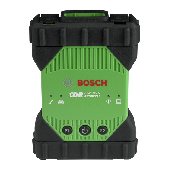
Page 5: Cdr 900 Components
CDR 900 Up- grade Kit (P/N 1699200630) or kits which may combine the CDR 900 and the CDR DLC Basic Kit with the older style CDR vehicle interface (CANplus Module). Regard- less of the kit offered, the CDR 900 main components... -
Page 6: Universal Serial Bus (Usb)
PC, you will Wireless Local Area Network (WLAN) need to connect 12V DC to the CDR 900. To power the The 802.11g WLAN connection on the CDR 900 is set CDR 900 with 12V DC for this purpose, plug in the CDR... -
Page 7: Supported Interfaces
Supported Interfaces The following sections list the interfaces supported by the CDR 900. It is not typical that CDR users require This cable is essential for powering the CDR 900 device this information but, it is important to note for those during setup, registration, programming and subse- interested the capabilities of the CDR 900. - Page 8 Connecting new CDR 900 device. the CDR 900 directly to an ECU to download EDR data requires a vehicle specific CDR cable and possibly an 4.12.4 1 m Extension Cable (P/N: 1699200617) adapter such as the CDR 500 FlexRay Adapter.
-
Page 9: Cdr 900 Vci Manager Software
Identifying Your CDR 900 by Serial Number to the CDR Tool Software for the latest instructions on The best way to keep track of your CDR 900 is by refer- getting the CDR 900 setup and registered for use. ring to the Serial Number on the back label of the CDR 900. -
Page 10: Cdr 900 Software Setup
Manager window depending on how the CDR 900 is connected to the PC. Icon Description 2. When you click on the new CDR 900 icon in the CDR CDR 900 VCI Manager will connect to CDR 900 900 VCI Manager screen, the Connect button will via USB... -
Page 11: 4.15 Setting Up Wireless Communications (Software
Registration can only be completed cable. Do not plug the CDR 900 USB cable into a when the CDR 900 is connected to the PC with the USB USB hub. cable and 12V power is supplied to it. Registration can- 2. -
Page 12: Checking Cdr 900 Firmware
CDR 900 and verifies the device can be communicated 1. Connect the 26-pin end of the CDR 900 Power and In- with and that is has the latest software. Users must en-... -
Page 13: Connecting The Cdr 900 To An Ecu
Vehicle LED is Blinking Red LED turns off. 3. Disconnect the CDR 900's DLC cable from the ve- If the CDR 900 does not detect 12V on Pin 16 of the hicle. DLC cable or that power is appled to CDR 900 Power 4. -
Page 14: Cdr 900 Speaker Is Beeping
Wireless Communication with Net- When the CDR 900 detects 12V on Pin 16 or when pow- work Unsuccessful using the Wire- ered though the cable, the Vehicle LED will stop blink- less 802.11n Dongle... -
Page 15: The Cdr 900 Over Wireless
• Does CDR 900 VCI Manager detect the device? • If the CDR 900 VCI Manager is still not able to com- If NO, then: municate with the CDR 900, perform the Recovery • Try a different USB Cable / Port on the PC Procedure on the CDR 900. -
Page 16: Recovering The Cdr 900 Software
You may see several symptoms such BITS PER SECOND as error messages directing you to go to RECOVERY CRASH DATA RETRIEVAL mode or an inability to connect to a detected CDR 900. CURSER HIGHLIGHTED TEXT OR DATA ON A DIS- PLAY SCREEN... -
Page 17: Hardware Specifications
Hardware Specifications | CDR 900 | 17 Hardware Specifications The following table lists the various hardware charac- teristics of the CDR 900. CDR 900 HARDWRE SPECIFICATIONS HOST INTERFACE Wired USB High Speed Client Port (480 Mbps) Ethernet 10/100 Mbps Wireless 802.11b/g/n on USB Dongle... -
Page 18: Warranty Information
DING ANY WARRANTY IMPLIED BY LAW, WHETHER FOR Products) it distributes through distributors authorized MERCHANTABILITY OR FITNESS FOR A PARTICULAR to sell Bosch products to be free from defects in mate- PURPOSE OR OTHERWISE AND SHALL BE EFFECTIVE rial and workmanship, in accordance with the following: ONLY FOR THE PERIOD THAT THIS EXPRESS WARRAN- TY IS EFFECTIVE. -
Page 19: Liability, Copyrights And Trademarks
© 2000 - 2018 Robert Bosch GmbH and Bosch Automo- tive Service Solutions Inc. All rights reserved, worldwide. The information in this CDR 900 User Manuals and CDR 900 VCI Manager software is subject to change without notice. The software described in the software help file... - Page 20 Bosch Automotive Service Solutions 2030 Alameda Padre Serra 93103 Santa Babara, CA www.boschdiagnotics.com/CDR/ 1699200755 | 2018-07-01...