Table of Contents
Advertisement
Quick Links
Advertisement
Table of Contents

Related Manuals for Motorola APX


Summary of Contents for Motorola APX
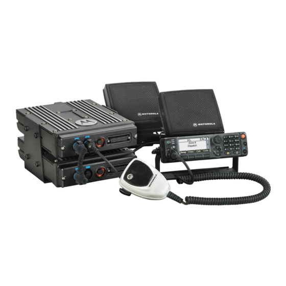
- Page 1 ASTRO APX MOBILE DUAL-RADIO O7 CONTROL HEAD SYSTEM INSTRUCTION MANUAL...
-
Page 3: Foreword
No duplication or distribution of this document or any portion thereof shall take place without the express written permission of Motorola. No part of this manual may be reproduced, distributed, or transmitted in any form or by any means, electronic or mechanical, for any purpose without the express written permission of Motorola. - Page 4 Notes...
-
Page 5: Table Of Contents
Introduction ................1-1 General............................1-1 1.1.1 APX Dual-Radio Software ....................1-2 Ordering Information ........................1-2 Notations Used in This Manual ......................1-3 Chapter 2 APX Mobile Dual-Radio Operation ........2-1 Overview ............................2-1 Initial Radio Setup ..........................2-1 O7 Control-Head Operation ......................2-2 2.3.1 Display..........................2-2 2.3.2 Basic Radio and Control Head Control ................2-2 2.3.3... - Page 6 FLASHport® Upgrade .......................2-7 APX Dual-Radio User Interface......................2-8 Chapter 3 Codeplug Configuration............3-1 Overview ............................3-1 3.1.1 Enabling APX Dual-Radio as Primary or Secondary Radio ..........3-1 3.1.2 Configuring APX Dual-Radio Emergency Operation............3-2 3.1.3 Configuring Secondary Radio Talkgroup Mute Operation..........3-3 3.1.4 Enabling Secondary Radio Transmission .................3-4 3.1.5...
- Page 7 Appendix A Other Configurations............A-1 Converting to a Single-Radio System ................... A-1 Changing the Control-Head Type....................A-1 Converting Radios Equipped With Dual-Radio Software into an APX Dual-Radio System ..A-1 Converting Radios Not Equipped With Dual-Radio Software into an APX Dual-Radio System..A-1 MN000770A01-AA...
- Page 8 Table of Contents Notes July 30, 2014 MN000770A01-AA...
-
Page 9: List Of Figures
List of Figures List of Figures Figure 2-1. APX Mobile Dual-Radio System Cabling Interconnect Diagram For O7 Remote Mount ..2-1 Figure 2-2. O7 Control Head........................2-2 Figure 2-3. Primary Radio Selected Diagram ..................2-8 Figure 2-4. Secondary Radio Selected Diagram ..................2-8 Figure 3-1. Enabling the APX Dual-Radio as Primary or Secondary Radio ..........3-1 Figure 3-2. -
Page 10: July
viii List of Figures Notes July 30, 2014 MN000770A01-AA... -
Page 11: List Of Tables
ASTRO APX Mobiles O2, O3, O5, O7 & O9 Control Head Installation Manual ......6878215A01 ASTRO APX Mobile Radios & O2, O3, O5, O7 & O9 Control Head Basic Service Manual...6875964M01 ASTRO APX 7500 Mobile Radio O2 & O7 Control Head Detailed Service Manual ...... 68012006086 CPS Programming Installation Guide ..................... - Page 12 List of Tables Notes July 30, 2014 MN000770A01-AA...
-
Page 13: Chapter 1 Introduction
Mobile radios known as the “bricks” to operate together with a single O7 Control Head. The APX Dual-Radio only supports APX7500, APX6500, and APX6500Li transceivers, and it allows users to mix and match models across tiers and power levels. For example, an APX7500 High- Power radio can operate with an APX6500 Mid-Power radio. -
Page 14: Apx Dual-Radio Software
APX Dual-Radios are considered to be “In-Band” when at least one frequency band of one radio overlaps with any one band of the other radio (single or dual band). APX Dual-Radios are considered to be “Cross-Band” when entirely different frequency bands exist for the two radios (single or dual band). -
Page 15: Notations Used In This Manual
Introduction: Notations Used in This Manual Notations Used in This Manual Throughout the text in this publication, you will notice the use of notes, cautions, and warnings. These notations are used to emphasize that safety hazards exist, and care must be taken and observed. - Page 16 Introduction: Notations Used in This Manual Notes July 30, 2014 MN000770A01-AA...
-
Page 17: Chapter 2 Apx Mobile Dual-Radio Operation
The Unselected Radio is normally in the receive, scan, or emergency state. Customers connect the two APX Mobile radios to each other via a short CAN cable, and connect an O7 Control Head to one of the radios. -
Page 18: O7 Control-Head Operation
User's Guide (68012006034) for detailed information regarding the use and operation of the APX Mobile Radio with the O7 Control Head. All radio features which are normally accessible with a O7 Control Head, are supported in a APX Dual-Radio System unless otherwise noted in this manual. 2.3.1 Display The display shows the status of the currently selected mobile radio. -
Page 19: Backlight
The split screen is used to indicate the status of both radios in system. The APX Dual-Radio icon represents the selected radio, and shows the different states of the receiving radio. The receiving icon on the vertical banner indicates that the unselected radio is receiving, and user needs to do Radio Swap to talk. -
Page 20: Ptt Operation
NOTE: a) Simulcast operation, where both radios transmit simultaneously, is not supported. b) If the APX Dual-Radio is on “In-Band” combination, and the selected radio is transmitting, the unselected radio’s speaker is muted. -
Page 21: Gun Lock
2.4.6 Advanced Unmute Rule For APX Dual Radio In-Band combinations, when one radio is transmitting voice, the other radio will automatically mute but can still play tones and Voice Announcement. For APX Dual Radio Cross-band combinations, customers are given the option of having the other radio mute or remain unmuted. -
Page 22: Radio Profile
2.4.11 Model Display While powering up, the O7 Control Head displays the model of the radio, for example APX7500, APX6500 or APX6500 Li. For APX Dual-Radio, it only displays the model of the Primary radio. 2.4.12 Data Terminal Data terminals can connect either to the transceiver or to the control head. If connected to the control head, the data terminal sets up a connection with the Primary Radio only. -
Page 23: Button Configuration
For CPS programming, a Primary Radio or a Secondary Radio can be powered independently in a standalone configuration, or can be connected in an APX Dual-Radio System. When connected in an APX Dual-Radio System, the radios cannot be programmed simultaneously. When one radio enters program mode, the other radio will not be allowed to enter program mode until the Dual-Radio System resets. -
Page 24: Apx Dual-Radio User Interface
APX Mobile Dual-Radio Operation: APX Dual-Radio User Interface APX Dual-Radio User Interface Enlarged white box indicates Primary Radio is selected Waves indicate audio is being received on Secondary Radio Gray background indicates Primary Radio is selected Waves indicate audio is being... -
Page 25: Chapter 3 Codeplug Configuration
Chapter 3 Codeplug Configuration Overview Following are the codeplug setting instructions, for configuring a mobile radio to function as part of the APX Dual-Radio System. Using CPS, the APX Dual-Radio options can be enabled in the Radio Configuration->Radio Wide->Dual Radio screen. 3.1.1 Enabling APX Dual-Radio as Primary or Secondary Radio In a Dual-Radio configuration, the radio selection determines which radio is the “Primary Radio”... -
Page 26: Configuring Apx Dual-Radio Emergency Operation
Codeplug Configuration: Overview 3.1.2 Configuring APX Dual-Radio Emergency Operation User selects which radio in a Dual-Radio configuration will handle the Emergency Mode Operation. It could be either the currently selected radio or the pre-determined Primary or Secondary Radio. This feature applies on a radio-wide basis. -
Page 27: Configuring Secondary Radio Talkgroup Mute Operation
Codeplug Configuration: Overview Figure 3-2. APX Dual-Radio Emergency Mode Operation Configuration There are three selections for the Emergency Radio as follows: 1. Selected Radio - When Emergency Mode is activated, the emergency transmission is sent on the currently user selected radio. -
Page 28: Enabling Secondary Radio Transmission
Enabling Secondary Radio Transmission The APX Dual-Radio CPS provides the capability to enable and disable the Secondary Radio transmission. It allows the Secondary Radio in APX Dual-Radio to transmit on the current channel, and this feature works on a Radio Wide basis. -
Page 29: Configuring Cross Band Mute Operation
3.1.5 Configuring Cross Band Mute Operation The Cross Band Mute Operation causes the speaker of the unselected radio in an APX Dual-Radio configuration to remain muted to receive audio, when the currently selected radio is transmitting voice and both radios are operating in a “cross-band” combination (operating in completely different frequency bands). -
Page 30: Enabling Fixed Swap Menu
Codeplug Configuration: Overview 3.1.6 Enabling Fixed Swap Menu Enables a “Radio Swap” menu selection to always appear in the left-most menu position of the control head in a Dual-Radio configuration, even when the radio user scrolls through the soft-menu buttons. Figure 3-6. -
Page 31: Chapter 4 Troubleshooting
If the error cannot be recovered, the radio keeps resetting before it enters the maintenance mode. See Chapter 3, "Codeplug Configuration" details on codeplug configuration. The improper APX Dual-Radio setup can have any of the following radio combination: • two Primary Radios •... -
Page 32: Control Head Id Error
Control Head ID Error The APX Dual-Radio only allows the O7 Control Head ID to be set to #1. If the ID is not set as required, “CH ID# ERR” shall be displayed and the radio is not able to function. User can use the control head Front Panel Programming feature to change the control head ID. -
Page 33: Error Display
Note: 01, 02, or 09 denotes a failure on the Primary Radio. 21, 22, or 29 denotes a failure on the Secondary Radio. See the ASTRO APX Mobile Radios and Control Heads Basic Service Manual (P/N 6875964M01) for all other error codes. - Page 34 Troubleshooting: Error Display Notes July 30, 2014 MN000770A01-AA...
-
Page 35: Chapter 5 Apx Dual-Radio Installation
SPEAKER 1 CABLE EMERGENCY FOOT SWITCH PRIMARY SECONDARY 07 CONTROL RADIO RADIO HEAD Figure 5-1. Side By Side Installation For APX Mobile Mid-Power Dual-Radio O7 Control Head System FUSE FUSE BATTERY SPEAKER 1 FUSE ANTENNA ANTENNA BLOCK EMERGENCY FOOT SWITCH... -
Page 36: Trunk Units
The Stack Mounting is only available for MP-MP combination, when both radios are Mid-Power models. For the APX Mobile Radio Mounting, refer to (Section 2.2, Radio Mounting) of the APX Mobiles And Control Heads Installation Manual (P/N 6878215A01). 5.2.1.1 Side-By-Side Installation... -
Page 37: Dual-Radio Combined Audio Configuration
• Connect the DC Power Cables (P/N HKN4192_), to each radio. Connect the other end of the cables to the battery terminals (RED POSITIVE). • Install the O7 Control Head, refer to the APX Mobiles And Control Heads Installation Manual (P/N 6878215A01). -
Page 38: Cables
Secondary Radio (female connector, labeled “Control Unit”). Securely tighten these two screws as well. The quick-disconnect end of the APX Dual-Radio Cable will attach to the O7 Control Head, and is mounted in the operator’s compartment. This end of the cable also contains the connections for the speakers, the emergency foot switch, and the ignition sense. -
Page 39: Ignition Cable
All cables should be pushed out of the way as much as possible to prevent damage. 5.2.2.3 Ignition Cable The APX Dual-Radio Cable (HKN6250_) has an ignition sense cable that must be used with every mobile installation. The ignition sense cable allows the radio to be turned on and off with the vehicle ignition switch, and allows the radio to remember the state of the radio on/off switch, even if it is changed while the vehicle is off. -
Page 40: Dual-Radio Accessory Cable
Refer to Figure 5-5, the APX Dual-Radio Cable (P/N HKN6250_) cable connects the O7 Control Head kit (P/N PMN1035_), to the dual remote radios via the quick-disconnect. NOTE: Follow standard installation practices when routing and connecting all system cables. Use labels to identify both ends of each cable and make sure that all connections are electrically sound. -
Page 41: Operator Compartment Units
5.6.2 Speaker Mounting Connect both speakers to the gray, two-pin connectors at the quick-disconnect end of the APX Dual- Radio Cable (P/N HKN6250_) cable. Note the speaker wires are black/red and black/violet for the Primary radio and are green and orange for the Secondary Radio. Be sure the plugs are fully seated, and then tie up any surplus cable. - Page 42 APX Dual-Radio Installation: Antenna Mounting As stated above, the antennas have a better ground plane the farther away from the edge of the roof. The antennas must also be a reasonable distance from each other to minimize the interference between them.
-
Page 43: Appendix A Other Configurations
5. Connect a standard O7 Control Head and cable to the newly configured APX Mobile Single-Radio System. Changing the Control-Head Type • The APX Dual-Radio System is only compatible with the O7 Control Head, and all other control head types are not supported. Converting Radios Equipped With Dual-Radio Software into an APX Dual-Radio System 1. - Page 44 A-2 Other Configurations: Converting Radios Not Equipped With Dual-Radio Software into an APX Dual-Radio System Notes July 30, 2014 MN000770A01-AA...
- Page 46 MOTOROLA, MOTO, MOTOROLA SOLUTIONS and the Stylized M logo are trademarks or registered trademarks of Motorola Trademark Holdings, LLC and are used under license. All other trademarks are the property of their respective owners. © 2014 Motorola Solutions, Inc. All rights reserved.