Table of Contents
Advertisement
Quick Links
Advertisement
Table of Contents

Related Manuals for Haier MVAB009MV2AA


Summary of Contents for Haier MVAB009MV2AA
-
Page 1: Service Manual
MINI 4-way Cassette Service Manual SYJS-07-2017 REV.A Edition: 2017-07... -
Page 2: Table Of Contents
CONTENTS 1. Feature ............................1 2. Specification ..........................2 3. Dimension ..........................5 4. Piping diagram ........................6 5. Wiring diagram ........................7 6. Electric characteristics ......................8 7. Air velocity and temperature distribution .................9 8. Sound pressure level ......................11 9. Installation ..........................12 9.1 Parts and functions ......................12 9.2 Safety ..........................13 9.3 Maintenance ........................15 9.4 Fault checkup ........................17... -
Page 3: Feature
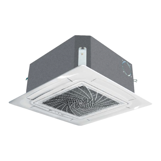
1. Feature • Compact design • New panel design 620*620mm • Low sound level... -
Page 4: Specification
2. Specification MVAB009MV2AA Rated Cooling Capacity Btu/hr 9,000 Rated Heating Capacity Btu/hr 10,000 Voltage, Cycle, Phase V/Hz/- 208/230-60-1 Fan Speed Stages 3+Auto Airflow (High/Med/Low) CFM 700/590/480 Motor Speed (High/Med/Low) RPM 760/650/520 Indoor Sound Level dB (High/Med/Low) 32/30/29 Grill Model PB-620KB... - Page 5 MVAB012MV2AA Rated Cooling Capacity Btu/hr 12,000 Rated Heating Capacity Btu/hr 13,500 Voltage, Cycle, Phase V/Hz/- 208/230-60-1 Fan Speed Stages 3+Auto Airflow (High/Med/Low) CFM 700/590/480 Motor Speed (High/Med/Low) RPM 760/650/520 Indoor Sound Level dB (High/Med/Low) 32/30/29 Grill Model PB-620KB Chassis Dimension: Height in (mm) 10 1/4 (260) Chassis Dimension: Width in (mm) 22 7/16(570)
- Page 6 MVAB018MV2AA Rated Cooling Capacity Btu/hr 19,000 Rated Heating Capacity Btu/hr 21,000 Voltage, Cycle, Phase V/Hz/- 208/230-60-1 Fan Speed Stages 3+Auto Airflow (High/Med/Low) CFM 700/590/480 Motor Speed (High/Med/Low) RPM 760/650/520 Indoor Sound Level dB (High/Med/Low) 33/30/29 Grill Model PB-620KB Chassis Dimension: Height in (mm) 10 1/4 (260) Chassis Dimension: Width in (mm) 22 7/16(570)
-
Page 7: Dimension
3. Dimension Unit: inch(mm) Indoor unt 22 7/16 570 ( ) less than100 ⑦ decoration board 24 7/16(620) pipe connection diagram connect drain pipe ⑥ ⑤ connect freh air inlet accessory Φ4( 100 )(direct installation) ④ 22 13/16 580 2 3/8(60) 2 3/8(60) (... -
Page 8: Piping Diagram
4. Piping diagram... -
Page 9: Wiring Diagram
5. Wiring diagram... -
Page 10: Electric Characteristics
6. Electric characteristics Indoor fan Units Power supply Power input (w) motor Volt. Output Model Phase Voltage Cooling Heating range MVAB009MV2AA 50/60 198~242 0.325 1.04 0.26 MVAB012MV2AA 50/60 198~242 0.325 1.04 0.26 MVAB018MV2AA 50/60 198~242 0.325 1.04 0.26 Symbols: MCA: Min. circuit amps (A) MFA: Max. -
Page 11: Air Velocity And Temperature Distribution
7. Air velocity and temperature distribution a. Cooling / Air velocity distribution Cooling Blowy angle: 40 Air velocity distribution 2.7m 1.5m/s 1.5m/s 1.0m/s 1.0m/s 0.5m/s 0.5m/s b. Cooling / Temperature distribution Cooling Blowy angle: 40 Temperature distribution 2.7m... - Page 12 c. Heating / Air velocity distribution Heating Blowy angle: 70 Air velocity distribution 2.7m 1.5m/s 1.5m/s 1.0m/s 1.0m/s 0.5m/s 0.5m/s d. Heating / Temperature distribution Heating Blowy angle: 70 Temperature distribution 2.7m 27℃ 27 ℃ 25 ℃ 25℃ 22 ℃ 22℃...
-
Page 13: Sound Pressure Level
1) Testing illustrate: 2) Testing condition: a: Unit running in the normal condition b: Test in the semi-anechoic chamber c: Noise level varies from the actual factors, such as room structure, etc. MVAB009MV2AA MVAB012/018MV2AA Limit of Limit of audible audible... -
Page 14: Installation
9. Installation 9.1 Parts and functions Outlet guide plate electrical cabinet (air direction can be adjusted by using direction adjustment key on the remote controller) Air-inlet grille Air filter (inside air-inlet grille) -
Page 15: Safety
• Only use branches supplied by Haier. Use of any other branches will void warranty. • Keep the condensate drain pipe away from toxic gas vents to prevent possible pollution of indoor environment. - Page 16 Attention • Do not put any heating apparatus under the • 3-minutes protection indoor units. The heat may cause distortion of the To protect the unit, there is a 3-minute time-out units. after the unit stops or after power is applied. •...
-
Page 17: Maintenance
9.3 Maintenance Attention • Repair can only be performed by licensed service technicians. • Before touching the electrical connections, all power supplies should be turned off. Only after switching off the power supply can the operator clean the air conditioner otherwise there is a risk of electric shock or injury. •... - Page 18 Installing air cleaner and air inlet grid: 1. Mounting the filter: opposite of dismantling the filter (as shown in hinge Fig. 3 above). lock port 2.Mounting the air inlet grid: as shown in the right figure, clip the locks locks on the grid as directed by the arrows, put the side with the hinges into the lock port, and then put the side with locks into the panel frame.
-
Page 19: Fault Checkup
9.4 Fault Checkup Please check the following when consigning repair service: Symptoms Reasons Water flow sound can be heard during starting operation, during operation or immediately after stopping operation. When it starts for 2-3 Water flow sound minutes, the sound may become louder, which is the flowing sound of refrigerant or the draining sound of condensate water. -
Page 20: Installation Procedures
9.5 Installation Procedures Caution: Choose a suitable installation location. Avoid places with high salinity (salt water) and high sulfur gas. Unit will corrode and damage will not be covered by warranty. Avoid excess oil (including mechanical oil) and steam. This can reduce efficiencies and product performance. Avoid areas where machines generate high frequency electromagnetic waves. - Page 21 gap between studs 21in(535mm) The ceiling and decorated board overlapping part should be more than 0.98in(25mm) indoor unit 22.4in(570mm) ceiling 23.2 in(590mm) decorated board 24.4in(620mm) decorated board ceiling Note: Before suspending the indoor unit, select an installation location according to the piping and wiring in the ceiling, and determine the direction of the piping.
- Page 22 Attention • For proper drainage, the drainpipes should be connected according to the installation manual. • Insulate the drainpipes to prevent exterior condensation. • Follow local plumbing codes when connecting drainpipes. Requirements: • The drainpipe of the indoor unit should be insulated. •...
- Page 23 • Confirm sound from the motor of the drainage pump and check for proper drainage. 3.9in(100 mm) below joint of drainpipe under the ceiling Tubing Permissible Length & Height Difference Please refer to the Haier MRV selection software. Model MVAB009~018MV2AA Tubing Materials & Specifications Gas pipe Ø1/2"(Ø12.7) Tubing Size in Please refer to the manual of the outdoor unit.
- Page 24 Installing the decorated panel on the body of indoor unit: receiving window for remote control the lamp will not flash when wired controller is used • Prior to attaching the panel to the unit locate the louver motor connector on the panel and the unit.
-
Page 25: Electrical Wiring
9.6 Electrical Wiring WARNING • Follow local codes when selecting wire gauge and connecting to house power. • Use the cable strain relief clips and locking conduit clamps to prevent wires from being pulled off terminal posts. • Unit must be properly grounded. Do not use water or gas piping, phone ground or lightning rod. Attention •... - Page 26 Signal Wiring Drawing Outdoor P Q A B C Communication wire between indoor & outdoor Control wire for wired controller with polarity without polarity Indoor 1 Indoor 2 Indoor 3 (950 CASSETTE) A B C P Q A B C P Q A B C A B C Wired controller...
- Page 27 Wire gauge size and breaker size for total indoor amp draw. Current NEC guidelines and local codes will trump this chart. Items Cross Rated Rated current of residual Section Length Current of Circuit Breaker(A) Cross Sectional Total in.(m) Overflow Ground Fault Interrupter(mA) Area of Signal Line Current of Breaker(A)
-
Page 28: Pcb Photo
10. PCB Photo 0151800244BA... -
Page 29: Dip Switch Setting
5# (wire controlled slave unit) ∙∙∙ ∙∙∙ ∙∙∙ ∙∙∙ ∙∙∙ 15# (wire controlled slave unit) Capability of indoor unit SW1_5 OFF OFF 9000BTU (MVAB009MV2AA) SW1_6 Capability of SW1_7 indoor unit OFF OFF 11000BTU (MVAB012MV2AA) SW1_8 18000BTU (MVAB018MV2AA) (B) Definition and description of SW3... - Page 30 Special function 1. Emergency switch: Press the emergency switch in stop condition, indoor unit operate with AUTO, AUTO SPEED, 24 Setting modes, pressure the emergency switch in start condition, indoor unit will stop operation. 2. Temp. compensation: The heating mode, the temp. compensation range is -14 ~ 0 . Set the temp.
-
Page 31: Indoor Unit Control
12. Indoor unit control 12.1 Cooling operation Set temp. in cooling: Ts=set temp. wired controller; After startup, indoor unit will send the request to outdoor according to the temp. difference between the set temp. and the room temp. 12.2 Heating operation Set temp. -
Page 32: Filter Cleaning
12.8 Anti-freeze protection In cooling mode, execute the anti-freeze protection due to the measured indoor coil temp. to avoid the indoor heat exchanger causing frost or ice. 12.9 Swing motor control Indoor will control swing motor ON/OFF due to the swing signal from wired controller. 12.10 Auxiliary electric heater control In heating mode, if the below conditions can be met, the electric heater will work: (1) Indoor fan motor and compressor are running;... -
Page 33: Failure Code
13. Failure code Failure code PCB LED5(Indoor at wired Units)/ Receiver Timer Fault Descriptions controller Lamp(Remote Controller) Fault of indoor unit ambient temp. transducer TA Fault of indoor unit pipe temp. transducer TC1 Fault of indoor unit pipe temp. transducer TC2 Fault of indoor unit dual heat source temp. -
Page 34: Troubleshooting
14. Troubleshooting Indoor failure diagnose [08] Indoor drainage system failure/float switch circuit on indoor PCB failure Reconnect If CN13 is fixed well If float switch works If CN4 is Modify the wiring with AC220V and the circuit voltage Check indoor PCB and replace it if necessary If water pump works Check water pump... - Page 35 [05] EEPROM failure If the chip is fixed well Reconnect Replace it If the chip is damaged Check if PCB is faulty, if yes, replace it [09] Indoor address repeated If wiring between P and Modify the wiring Q is normal If communication wire is Modify the communication connected with multi...
- Page 36 [06] Communication circuit between indoor and outdoor If wiring between P and Modify the communication wire Q is wrong or broken down If the port of CN15 on Modify the port indoor PCB is normal If the port of CN19 on outdoor connecting board is normal Electrify the outdoor If outdoor power source is normal...
- Page 37 [07] Communication abnormal between indoor and wired controller If wiring of terminal A, B, C of Modify the wiring wired controller is proper If the broken wire or port is Modify the connection fixed improperly If in group operation Set one indoor If there is indoor unit unit as No.
- Page 38 [12] No 50Hz zero passage signal Check if the Replace transformer is well transformer Check if the wiring of the Reconnect wired controller connect well Replace PCB...
- Page 39 [14] DC motor failure Check if the wiring of motor Reconnect is fixed well Replace motor If the motor is fault Replace the PCB...
- Page 40 [18] The 4-way valve of 3-pipe valve box reversing failure Adjust it correctly by after-sales If the 4-way valve of 3-pipe personnel on site. valve box is internal leakage Check if the TC1 and TC2 of indoor Adjust it correctly by after-sales unit are normal, if the resistance is personnel on site.
-
Page 41: Capacity
7071 9321 7071 9964 7071 10286 6750 8357 6750 8679 7071 9000 6750 9321 7071 9321 7071 9643 7071 9964 6750 MVAB009MV2AA 90.5 8357 6750 8679 7071 9000 6750 9000 6750 9321 7071 9643 7071 9964 6750 8357 6750 8357... - Page 42 6563 6563 6563 7500 7500 7500 6875 8438 8438 7813 6875 9688 9375 7813 6875 36.5 10000 10000 7813 6875 MVAB009MV2AA 42.8 10000 10000 7813 6875 43.7 10625 10000 7813 6875 11250 10000 7813 6875 54.5 11875 10000 7813 6875 59.9...
- Page 43 Haier Commercial Air Condition Web: Http://www.haier.com Haier reserves the right to make change without any notice.