Advertisement
Quick Links
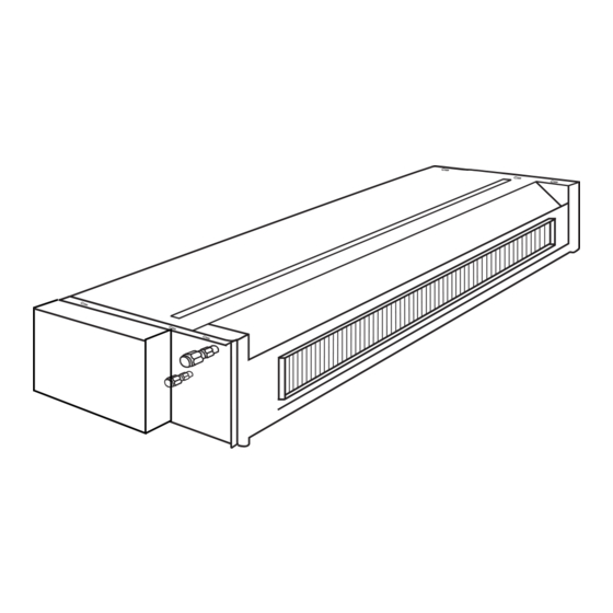
CEILING CONCEALED TYPE AIR CONDITIONER
INDOOR UNIT
OPERATION & INSTALLATION
MANUAL
SERIES 09~21 MODEL
SERIES 07 MODEL
No.
0010573331
Please read this manual carefully before use.
Please keep it attentively for future use.
SERIES 24 MODEL
H-MRV
Ceiling Concealed Type Room Air Conditioner
Contents
Before Application
Cautions
Part Description
Important Points of Safety
Maintenance
Trouble Shooting
When Fault Occurs
Notice to Users
Indoor Unit Installation
Installation Precautions
Installation Procedure
Installation Check and Trial Run
AE072FCAKA
AE122FCAKA
AE092FCAKA
AE142FCAKA
1
2
3-5
6-7
8
9
10-11
12-17
18
AE182FCAKA
AE212FCAKA
AE242FCAKA
Advertisement

Related Manuals for Haier MRV 09 Series


Summary of Contents for Haier MRV 09 Series
- Page 1 CEILING CONCEALED TYPE AIR CONDITIONER INDOOR UNIT OPERATION & INSTALLATION MANUAL H-MRV Ceiling Concealed Type Room Air Conditioner Contents Before Application SERIES 09~21 MODEL Cautions Part Description Important Points of Safety Maintenance Trouble Shooting When Fault Occurs Notice to Users SERIES 07 MODEL Indoor Unit Installation Installation Precautions...
- Page 2 Cautions Disposal of the old air conditioner Safety Instructions and Warnings Before disposing an old air conditioner that goes out of use, please make sure it's Before starting the air conditioner, read the inoperative and safe. Unplug the air information given in the User's Guide conditioner in order to avoid the risk of child carefully.
- Page 3 Series 07 Series 24 Series 09-21 have the Return air box (see the following picture) when shipping from the factory and they are back-side return air. During the installation, also can be changed to Down-side Return air according to the user's need. Series 09~21...
- Page 4 Important Points of Safety The following four important points of safety and suggestions should be paid great attention: Warning: Misuse may cause fatal result such as death or serious injury etc. Attention: Misuse may cause human injury or damage of machine, in some case fatal results.
- Page 5 Important Points of Safety Warning Avoid your body being blown If something abnormal (e.g.: burnt directly by cold wind for long smell etc.) occurs, stop running the period, otherwise your health machine, shut down the manual may be affected. power switch and contact after service.
- Page 6 Important Points of Safety Attention Ensure ventilation of the room DON’T lay any burning facilities if the machine is used with in place where winds produced by burning facilities. Deficient the machine can reach. Incomplete ventilation can cause oxygen combustion of burning facility may shortage.
- Page 7 Trouble Shooting The following cases are not troubles. Water flow sound is heard. During operation, the air conditioner may sometimes exhibit a sound of "clatter" or "Hua-Hua" "rumble". This is the common sound of refrigerant flow but not a trouble. This is caused by the thermal expansion A sound of "Pi-Pa"...
- Page 8 Trouble Shooting During DRY operation, there is no air sent out or fan speed cant be changed. In HEAT mode, the outdoor unit This occurs during removal of the frost generates water or steam. (in defrosting operation) on the radiator of outdoor unit.
- Page 9 When Fault Occurs Poor cooling or heating Is the operation controller Is there any door or window Are there any obstructs adjusted as required? left open? before the air inlet or outlet? Poor cooling Is there any other heat Is there any direct sunlight Are there too many people source in the room? into the room?
- Page 10 Notice to Users Notice to users To ensure proper operation of the system, the user shall follow this instruction manual to install the unit. When handling the air conditioner, please be care not to scratch the case surface. This instruction manual describes the installation method aided with the installation tools specified by manufacturer .
- Page 11 Installation Precautions Before installing, do read this "Safety precautions" carefully to guarantee the proper installation. The below attentive matters are divided into" Warning" " and " Note" two parts. When the wrong installation occur, it is very possible death and severe injury and other serious accidents will happen.
- Page 12 ! Attention This description does not address to all possible cases. For new requirement and query, please consult the regional sales center of Haier Air Conditioner General Co., Ltd. ! Warning This instruction manual must be read carefully before beginning of installation, improper ins- tallation may cause accidents and thus bring about machine damage and personal casualty.
- Page 13 Installation Procedure After selecting the unit installation location, proceed the following steps: 1. Drill a hole in the wall and insert the connecting pipe and wire through a PVC wall-through tube purchased locally. The wall hole shall be with a outward down slope of at least 1/100. (See Figure 2) 2.
- Page 14 Installation Procedure Figure 4 Air outlet grille Return air bellows Air supply No obstacles within 1 m(0Pa) Unit Return air Each air return and supply duct should fix to the floor precast slab by using an iron stand. Use glue to seal the interface closely.
- Page 15 Installation Procedure 2. Installation of air return duct Use rivets to connect the air return duct to the air return inlet of the indoor unit. The other end connects to the air return shutter. as shown in Fig.2. air return air return duct shutter...
- Page 16 Installation Procedure Original concrete slab Use hole hinge, hole plunger or hole bolt. Steel reinforcement structure Hanging bolt Use steel angle or new support steel angle directly. Support steel angle Suspension screw Hanging of the indoor unit Fasten the nut on the suspension screw and then hang the suspension screw in the T slot of the suspension part of the unit.
- Page 17 Installation Procedure Hose Drain pipe size: Ø19.05mm (3/4") PVC pipe The hose is used for adjusting the off-center and angle of the rigid PVC pipe. Directly stretch the hose to install without making any deformation. The soft end of the hose must be fastened with a hose clamp. Please apply the hose on horizontal part Hose Hose clamp...
- Page 18 Installation Procedure Pipe expansion dimensions as follows: Pipe diameter Ø Size A (mm) Incorrect Correct 6.35 mm (1/4 " ) 0.8 ~ 1.5 9.52 mm (3/8 " ) 1.0 ~ 1.8 12.7 mm (1/2 " ) 1.2 ~ 2.0 Slope Damage Bur Partial Overlong 15.88 mm (5/8 "...
- Page 19 Installation Check and Trial Run Check if the drain pipe and connection wires are arranged properly. The drain pipe shall be put below. The connection wire shall be put above. Be sure to wrap the drain pipe (especially the indoor part and the part inside the machine) with thermal ins- ulating materials.