
Related Manuals for Toro 30410


Summary of Contents for Toro 30410
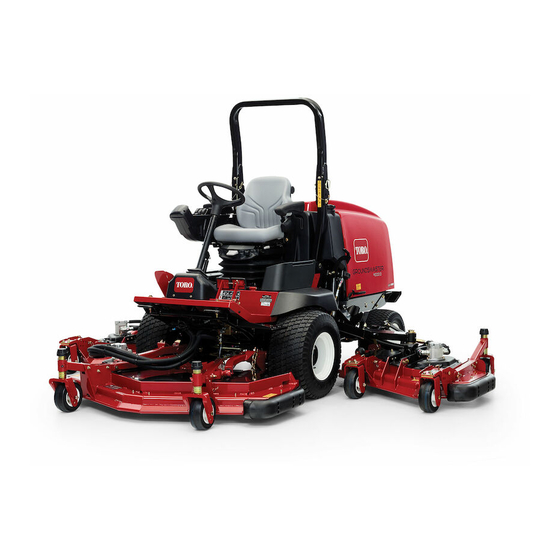
- Page 1 Form No. 3358-715 Rev B Groundsmaster ® 4000-D Traction Unit Model No. 30410—Serial No. 2800000001 and Up Model No. 30410TE—Serial No. 2800000001 and Up Register at www.Toro.com. Original Instructions (EN)
-
Page 2: Introduction
Whenever you need service, genuine Toro parts, or additional information, contact an Authorized Service Dealer or Toro Customer Service and have the model and serial numbers of your product ready. Write the numbers in the space provided. -
Page 3: Table Of Contents
Safety ................4 Belt Maintenance............ 44 Safe Operating Practices ........4 Servicing the Alternator Belt....... 44 Toro Mower Safety ..........6 Re-tensioning the Blade Drive Belts ....44 Sound Pressure Level ........... 7 Replacing the Blade Drive Belt ......45 Sound Power Level.......... -
Page 4: Safety
Preparation Safety • While mowing, always wear substantial footwear, This machine meets or exceeds CEN standard long trousers, hard hat, safety glasses, and ear protection. Long hair, loose clothing or jewelry may EN 836:1997, ISO standard 5395:1990, and ANSI get tangled in moving parts. Do not operate the B71.4-2004 specifications in effect at the time of production. -
Page 5: Maintenance And Storage
– Do not stop or start suddenly when going up or • Disengage drive to attachments when transporting downhill. or not is use. – The machine speed should be kept low on slopes • Stop the engine and disengage drive to attachment: and during tight turns. -
Page 6: Toro Mower Safety
The following list contains safety information specific near drop-offs, always have the ROPS installed. to Toro products or other safety information that you must know that is not included in the CEN, ISO, or • When operating a machine with a ROPS, always use ANSI standards. -
Page 7: Sound Pressure Level
• Never store the machine or fuel container inside only genuine Toro replacement parts and accessories. where there is an open flame, such as near a water Replacement parts and accessories made by other heater or furnace. manufacturers could be dangerous, and such use could void the product warranty. - Page 8 93-7275 100-5693 1. Read the Operator’s Manual. 2. Do not use starting aids. 1. Height of cut adjustment 100-6578 93-7818 1. Entanglement hazard, belt—do not operate the machine 1. Warning—read the Operator’s Manual for instructions on with the shields or guards removed; always keep the torquing the blade bolt/nut to 115 to 149 N•m (85 to 110 shields and guards in place;...
- Page 9 100-5694 104-3579 1. Height of cut adjustment 1. Low height of cut 2. High height of cut adjustment adjustment 104-3578 1. Height of cut adjustment 104-3599 1. Do not step here. 2. Traction pedal 3. Traction—forward 4. Traction—reverse 5. Danger—shut off PTO prior to raising the cutting units; do not operate the cutting units when they are in the raised position.
- Page 10 106–6752 (Affix over part no. 112–9118 for CE*) * This safety decal includes a slope warning required on the machine for compliance to the European Lawn Mower Safety Standard EN836:1997. The conservative maximum slope angles indicated for operation of this machine are prescribed by and required by this standard.
- Page 11 Battery Symbols 106-6755 Some or all of these symbols are on your battery 1. Engine coolant under 3. Warning—do not touch 1. Explosion hazard 6. Keep bystanders a safe pressure. the hot surface. distance from the battery. 2. Explosion hazard—read 4.
- Page 12 106-2046 1. Power Take-off (PTO) 6. Low 11. Silencer switch 16. Slow 2. Engage 7. Lock 12. Press the button 17. Continuous variable setting 3. Disengage 8. Flow divider 13. Key switch 18. Engine coolant temperature reset switch 4. Transmission 9.
-
Page 13: Setup
Setup Loose Parts Use the chart below to verify that all parts have been shipped. Procedure Description Qty. Seat kit (obtain separately) Seat suspension kit (obtain separately) Manual tube Install the seat, seat belt, and manual R-clamp tube. Seat belt Bolt Lock washer –... -
Page 14: Installing The Seat, Seat Belt, And Manual Tube
Greasing the Bearings and Bushings procedure of Lubrication , page 32. Failure to properly grease the machine will result in premature failure of critical parts. Installing the Seat, Seat Belt, and Manual Tube Replacing the Warning Decal Parts needed for this procedure: Seat kit (obtain separately) Parts needed for this procedure: Seat suspension kit (obtain separately) -
Page 15: Product Overview
Product Overview load, maximum ground speed, fully press the pedal while the throttle is in Fast. To stop, reduce your foot pressure on the traction pedal and allow it to return to the center position. Important: When in the mow position, the speed limiter screw must stop the traction pedal before the pump reaches full stroke or damage to the pump may occur. -
Page 16: Pto Switch
Glow Plug Indicator Light PTO Switch The PTO switch (Figure 4) has three positions: On When lit, the glow plug indicator light (Figure 2) (engage), Neutral, and Off (disengage). Carefully lift indicates that the glow plugs are on. and push the PTO switch forward to the On position to start the implement or cutting unit blades. -
Page 17: Specifications
• Alternate oil: SAE 10W-30 or 5W-30 (all Authorized Service Dealer or Distributor or go to temperatures) www.Toro.com for a list of all approved attachments and accessories. Toro Premium Engine Oil is available from your distributor in either 15W-40 or 10W-30 viscosity. See... -
Page 18: Adding Fuel
1. Park the machine on a level surface. Unlock the engine cover latches. If the engine has been running, the pressurized, 2. Open the engine cover. hot coolant can escape and cause burns. 3. Remove the dipstick, wipe it clean, install the •... - Page 19 flash point and cold flow characteristics which will ease starting and reduce fuel filter plugging. In certain conditions, fuel is extremely Use of summer grade fuel above 20° F (-7° C) will flammable and highly explosive. A fire or contribute toward longer fuel pump life and increased explosion from fuel can burn you and others power compared to winter grade fuel.
- Page 20 This is vegetable-oil based biodegradable oil tested and Checking the Hydraulic Fluid approved by Toro for this model. This fluid is not as resistant to high temperatures as standard fluid, so Service Interval: Before each use or daily...
- Page 21 Figure 9 1. Hydraulic tank cap Figure 10 4. Remove the dipstick from the filler neck and wipe it with a clean rag. Insert the dipstick into the filler 1. Check/drain plug neck; then remove it and check the fluid level. The fluid level should be between the two marks on the 2.
-
Page 22: Checking The Tire Pressure
Checking the Rear Axle Lubricant Service Interval: Every 400 hours The rear axle is shipped from the factory filled with SAE 85W-140 gear lube. Check the oil level before the engine is first started and every 400 hours thereafter. The capacity is 80 oz (2.4 l). Visually inspect for leaks daily. - Page 23 castor forks, add or remove an equal number of spacers below) onto the spindle shaft to get the desired from the castor forks, and secure the rear chain to the height-of-cut; then slide the washer onto the shaft. desired hole. Refer to the following chart to determine the combinations of spacers for the setting: 1.
- Page 24 Note: When using 1 inch (25 mm), 1-1/2 inch (38 mm), or occasionally 2 inch (51 mm) height-of-cut, move the skids and gage wheels to the highest holes. Side Cutting Units To adjust the height-of-cut on the side cutting units, add or remove an equal number of spacers from the castor forks, position the castor wheel axles in the high or low height-of-cut holes in the castor forks, and secure the...
- Page 25 Figure 23 Figure 21 Adjusting the Skids 8. Remove the hairpin cotters and clevis pins securing the damper links to the cutting unit brackets The skids should be mounted in the lower position (Figure 22). Align the damper link holes with the when operating in height of cuts greater than 2-1/2 selected height-of-cut bracket holes in the cutting inches (64 mm) and in the higher position when...
- Page 26 Front Cutting Unit Setup Rotate blade on each spindle until the ends face forward and backward. Measure from the floor to the front tip of the cutting edge. Adjust 1/8 inch shims on front castor fork(s) to match height of cut to decal (Figure 26);...
-
Page 27: Starting And Stopping The Engine
edge of side cutting unit to outside edge of front cutting unit. 4. If inside edge is still too high, remove an additional 1/8 inch shim from bottom of front inside castor arm of the side cutting unit and one 1/8 inch shim from the front outside castor arm of the side cutting unit. -
Page 28: Checking The Interlock Switches
start after 15 seconds, turn the key to the Off of the seat while the engine is running and the traction position, recheck the controls and procedures, pedal is in neutral. Although the engine will continue wait 15 additional seconds, and repeat the to run if the PTO lever is disengaged and the traction starting procedure. -
Page 29: Jacking Points
Jacking Points • On the front of the machine on the frame on the inside of each drive tire • On the rear of the machine at the center of the axle Tie Downs • On each side of the frame by the side cutting unit lift arms Figure 28 •... -
Page 30: Operating Tips
Operating Tips Another benefit of the brakes is to maintain traction. For example, in some slope conditions, the uphill wheel slips and loses traction. If this situation occurs, depress Mow When Grass is Dry the uphill turn pedal gradually and intermittently until the uphill wheel stops slipping, thus, increasing traction Mow either in the late morning to avoid the dew, which on the downhill wheel. -
Page 31: Maintenance
Maintenance Note: Determine the left and right sides of the machine from the normal operating position. Recommended Maintenance Schedule(s) Maintenance Service Maintenance Procedure Interval • Torque the wheel lug nuts. • Check the fan and alternator belt tension. After the first 10 hours •... -
Page 32: Premaintenance Procedures
If you leave the key in the ignition switch, someone could accidently start the engine and seriously injure you or other bystanders. Remove the key from the ignition before you do any maintenance. Premaintenance Procedures Service Interval Chart Figure 32 Lubrication •... - Page 33 Figure 33 Figure 36 Front Cutting Unit Figure 34 • Castor fork shaft bushings (2) (Figure 37) • Spindle shaft bearings (3) (located under the pulley) (Figure 38) • Idler arm pivot bushings (2) (Figure 38) Figure 35 Figure 37...
- Page 34 Figure 38 Front Lift Assemblies • Lift arm bushings (2) (Figure 39) • Lift cylinder bushings (4) (Figure 39) Figure 40 • Lift arm ball joints (2) (Figure 40) Side Cutting Units • Castor fork shaft bushing (1) (Figure 41) •...
- Page 35 • Bell crank pivot bushings (2) (Figure 44) • Rear arm bushings (4) (Figure 44) • Lift cylinder bushings (4) (Figure 45) Figure 44 Figure 42 Figure 45 Figure 43...
-
Page 36: Engine Maintenance
Engine Maintenance 3. Remove the primary filter (Figure 47). Cleaning of the used element is not recommended due to the possibility of damage to the filter media. Inspect the Air Cleaner Maintenance new filter for shipping damage, checking the sealing end of the filter and the body. -
Page 37: Servicing The Engine Oil And Filter
Servicing the Engine Oil and Fuel System Filter Maintenance Service Interval: After the first 50 hours Servicing the Fuel System Every 150 hours Change the oil and filter initially after the first 50 hours of operation; thereafter change the oil and filter every 150 hours. -
Page 38: Bleeding Air From The Injectors
2. Loosen the drain plug on the bottom of the filter 4. Tighten the pipe connector securely. canister. 5. Repeat the procedure on the remaining nozzles. Figure 51 1. Water separator filter canister 3. Clean the area where the filter canister mounts. 4. -
Page 39: Electrical System Maintenance
Electrical System Maintenance Battery electrolyte contains sulfuric acid which is a deadly poison and causes severe burns. Activating, Charging, and • Do not drink electrolyte and avoid contact with skin, eyes or clothing. Wear safety Connecting the Battery glasses to shield your eyes and rubber gloves to protect your hands. -
Page 40: Battery Care
Coat the battery posts and cable connectors with (+) terminal is all of the way onto the post and the Grafo 112X (skin-over) grease (Toro Part No. 505-47) cable is positioned snug to the battery. The cable or petroleum jelly to prevent corrosion. -
Page 41: Drive System Maintenance
Drive System ten or two o’clock position) until the level is up to the bottom of the brake housing check hole. Install Maintenance the plug. 8. Repeat the procedure on the opposite gear assembly. Changing the Planetary Gear Drive Oil Service Interval: After the first 200 hours Every 800 hours Change the oil initially after first 200 hours of operation. -
Page 42: Checking The Rear Wheel Toe-In
Checking the Rear Wheel Toe-In Service Interval: Every 800 hours After every 800 operating hours or annually, check the rear wheel toe-in. 1. Measure the center-to-center distance (at axle height) at the front and rear of the steering tires. The front measurement must be 1/4 inch (6 mm) less than the rear measurement. -
Page 43: Cooling System Maintenance
Cooling System Maintenance Servicing the Engine Cooling System Service Interval: Every 100 hours Every 2 years Remove debris from the oil cooler and radiator daily. Clean them more frequently in dirty conditions. Figure 62 1. Turn the engine off and raise the hood. Clean the 1. -
Page 44: Brake Maintenance
Brake Maintenance Belt Maintenance Servicing the Alternator Belt Adjusting the Service Brakes Service Interval: After the first 10 hours Adjust the service brakes when there is more than 1 inch Every 100 hours (25 mm) of “free travel” of the brake pedal, or when the brakes do not work effectively. -
Page 45: Replacing The Blade Drive Belt
Note: Make sure the belt is positioned on the spring side of the belt guide (Figure 64). Figure 65 Figure 64 1. Hydraulic motor 2. Mounting bolts 1. Belt 4. Belt guide 2. Eye bolt 5. Flange nut 3. Extension spring 6. -
Page 46: Controls System Maintenance
Controls System Maintenance Adjusting the Throttle Service Interval: After the first 50 hours Every 400 hours Adjust the throttle cable (Figure 66) so that the governor Figure 67 lever on the engine contacts the low and high speed set bolts before the throttle lever contacts the slot in the 1. -
Page 47: Hydraulic System Maintenance
Thereafter, change the filters after every 800 operating hours, in normal conditions. Service Interval: After the first 200 hours Use Toro replacement filters (Part No. 94-2621 for the Every 800 hours left side of the machine and 75-1310 for the right side Change the hydraulic fluid after every 800 operating of the machine). -
Page 48: Hydraulic System Test Ports
Hydraulic System Test Ports The test ports are used to test the pressure in the Figure 73 hydraulic circuits. Contact your local Toro distributor for assistance or refer to the Groundsmaster 4000 1. Test port C service manual. -
Page 49: Adjusting The Cutting Unit Flow Control
Figure 75 Figure 77 1. Test port E 1. Test port I 2. Test port H Test Port F (Figure 76), located under the seat, is used The counterbalance test port (Figure 78) is used to measure the lift circuit pressure. to adjust the pressure in the counterbalance circuit. -
Page 50: Mower Maintenance
Mower Maintenance Pivoting (Tilting) the Front Cutting Unit Upright Adjusting the Transport Latch Note: Although not needed for normal maintenance procedures, the front cutting unit can be pivoted (tilted) If the transport latch (Figure 80) has to be adjusted, to an upright position (Figure 82). Should you desire to adjust as follows: tilt the cutting unit, proceed as follows: 1. -
Page 51: Pivoting The Front Cutting Unit Down
Cutting unit pitch is the difference in height-of-cut from the front of the blade plane to the back of the blade plane. Toro recommends a blade pitch of 1/4 inch (6 mm). That is the back of the blade plane is 1/4 inch (6 mm) higher than the front. -
Page 52: Servicing The Castor Arm Bushings
Figure 87 1. Castor arm tube 2. Bushings 5. Apply grease to the inside and outside of the new bushings. Using a hammer and flat plate, drive the bushings into the mounting tube. 6. Inspect the castor spindle for wear and replace it if it is damaged. -
Page 53: Blade Maintenance
The blade must be replaced if a solid object is hit, the blade is out of balance, or if the blade is bent. Always use genuine Toro replacement blades to be sure of safety and optimum performance. Never use replacement blades made by other manufacturers because they could be dangerous. -
Page 54: Inspecting And Sharpening The Cutter Blade(S)
Important: The curved part of the blade must 1. Position the machine on a level surface. Raise the be pointing toward the inside of the cutting unit cutting unit, engage the parking brake, put the to ensure proper cutting. traction pedal in neutral, put the PTO lever in the Off position, stop the engine, and remove the Note: After striking a foreign object, torque all the ignition key. -
Page 55: Correcting Cutting Unit Mismatch
forward, and measure again. The difference between the dimensions must not exceed 1/8 inch (3 mm). If the dimension exceeds 1/8 inch (3 mm), replace If the blade is allowed to wear, a slot will form the blade because it is bent. Make sure to measure between the sail and flat part of the blade all of the blades. -
Page 56: Spark Arrestor Maintenance
C. Coat the cable terminals and battery posts with Grafo 112X skin-over grease (Toro Part No. 505-47) or petroleum jelly to prevent corrosion. D. Slowly recharge the battery every 60 days for 24 Do not stand in line with the clean-out port. -
Page 57: Schematics
Schematics Electrical Schematic (Rev. A) - Page 58 Hydraulic Schematic (Rev. F)
- Page 59 Notes:...
- Page 60 If for any reason you are dissatisfied with your Distributor’s service or have difficulty obtaining guarantee information, contact the Toro importer. If all other remedies fail, you may contact us at Toro Warranty Company.