
Related Manuals for Miele KM 6360


Summary of Contents for Miele KM 6360
- Page 1 Operating and Installation Instructions Induction Cooktops To prevent accidents and machine damage, read these instructions be‐ fore installation or use. en-US M.-Nr. 09 888 630...
-
Page 2: Table Of Contents
Contents IMPORTANT SAFETY INSTRUCTIONS..............4 Overview ....................... 15 KM 6360 / KM 6365....................15 KM 6370 / KM 6375....................16 KM 6377......................... 17 DirectSelection Plus controls ................. 18 Cooking zone data....................19 Before using for the first time................22 Cleaning the cooktop for the first time ..............22 Turning on the cooktop for the first time.............. - Page 3 Safety clearances....................54 Ventilation ......................58 Framed cooktops ....................59 Instructions for installation..................59 Installation dimensions ..................60 KM 6360 ......................60 KM 6370 ......................61 KM 6377 ......................62 Installation......................63 Flush-mounted (frameless) cooktops ..............64 Instructions for installation..................64 Installation dimensions ..................
-
Page 4: Important Safety Instructions
They contain important notes on installation, safety, use and maintenance. Miele cannot be held liable for damage occurring as a result of non-compliance with these instructions. Keep these instructions in a safe place and pass them on to any... - Page 5 IMPORTANT SAFETY INSTRUCTIONS This cooktop is intended for domestic use and use in other similar environments. This cooktop is not intended for outdoor use. The cooktop is intended for domestic use only to prepare food and keep it warm. Any other use may be dangerous. ...
- Page 6 IMPORTANT SAFETY INSTRUCTIONS Children As with any other appliance, children must be supervised. Do not leave children unattended: Children should not be alone or unsupervised in the area where the oven is installed. Do not allow them to sit or stand on the appliance. ...
- Page 7 Technical safety Installation, repair and maintenance work should be performed by a Miele authorized service technician in accordance with national and local safety regulations and the provided installation instruc‐ tions. Contact Miele’s Technical Service Department for examina‐ tion, repair or adjustment. Repairs and other work by unauthorized persons could be dangerous and may void the warranty.
- Page 8 If the power cord is damaged, it must be replaced by a qualified electrician with a special power cord, which is available from Miele Service. See "Electrical connection." The appliance must be completely disconnected from the elec‐...
- Page 9 Disconnect the cooktop from the power supply and contact Miele. If the cooktop is installed behind a cabinet door, do not close the door while the cooktop is in operation.
- Page 10 IMPORTANT SAFETY INSTRUCTIONS Proper use The cooktop gets hot when in use and remains hot for a while af‐ ter being turned off. There is a potential hazard until the residual heat indicator goes out. When in use, the cooktop emits a significant amount of heat, which can cause objects in the vicinity to catch fire.
- Page 11 IMPORTANT SAFETY INSTRUCTIONS If the cooktop is covered, there is a risk that the material of the cover will ignite, explode or melt if the range is still hot or if turned on inadvertently. Never cover the cooktop with a board, cloth or protec‐ tive sheet.
- Page 12 IMPORTANT SAFETY INSTRUCTIONS Do not allow solid or liquid sugar, or pieces of plastic or aluminum foil to get onto the burners when they are hot, as they can damage the ceramic surface when it cools down. If this should occur, turn off the appliance and scrape off all the sugar, plastic or aluminum resi‐...
- Page 13 IMPORTANT SAFETY INSTRUCTIONS Metal utensils stored in a drawer under the cooktop can become hot if the appliance is used intensively for a long time. Do not store any metal items or utensils in a drawer under the cooktop. ...
- Page 14 IMPORTANT SAFETY INSTRUCTIONS Cleaning and care Do not use a steam cleaner to clean the cooktop. The steam may reach electrical components and cause a short cir‐ cuit. If the cooktop is built in over a self cleaning oven, the cooktop should not be used while the self cleaning process is being carried out, as this could trigger the overheating protection mechanism on the cooktop (see relevant section).
-
Page 15: Overview
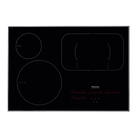
Overview KM 6360 / KM 6365 a Cooking zone with TwinBooster b Cooking zone with Booster c PowerFlex cooking zone with TwinBooster d PowerFlex cooking zone with TwinBooster cd can be combined to form PowerFlex cooking zone e DirectSelection Plus controls... - Page 16 Overview KM 6370 / KM 6375 a Cooking zone with Booster b PowerFlex cooking zone with TwinBooster c PowerFlex cooking zone with TwinBooster bc can be combined to form PowerFlex cooking zone d Cooking zone with Booster e Cooking zone with TwinBooster f DirectSelection Plus controls...
- Page 17 Overview KM 6377 a PowerFlex cooking zone with TwinBooster b PowerFlex cooking zone with TwinBooster ab can be combined to form PowerFlex cooking zone c Cooking zone with TwinBooster d PowerFlex cooking zone with TwinBooster e PowerFlex cooking zone with TwinBooster de can be combined to form PowerFlex cooking zone f DirectSelection Plus controls...
-
Page 18: Directselection Plus Controls
Overview DirectSelection Plus controls 0 1 2 3 4 5 6 7 8 9 0 1 2 3 4 5 6 7 8 9 0 1 2 3 4 5 6 7 8 9 0 1 2 3 4 5 6 7 8 9 0 1 2 3 4 5 6 7 8 9 Sensor buttons a Turning the cooktop On/Off... -
Page 19: Cooking Zone Data
to Time in minutes . to . Time in hours System lock/Safety lock activated Demo mode activated Cooking zone data KM 6360 / KM 6365 Cooking Output in watt** Diameter* Ø zone Inches Centimeters 208 V 240 V 7–11... - Page 20 Overview KM 6370 / KM 6375 Cooking Output in watt** Diameter* Ø zone Inches Centimeters 208 V 240 V 6–9 15–23 Normal 1900 2200 TwinBooster, Level 1 2700 3100 TwinBooster, Level 2 3350 3850 6–9 15–23 Normal 1900 2200 TwinBooster, Level 1 2700...
- Page 21 Overview KM 6377 Cooking Output in watt** Diameter* Ø zone Inches Centimeters 208 V 240 V 6–9 15–23 Normal 1900 2200 TwinBooster, Level 1 2700 3100 TwinBooster, Level 2 3350 3850 6–9 15–23 Normal 1900 2200 TwinBooster, Level 1 2700 3100 TwinBooster, Level 2...
-
Page 22: Before Using For The First Time
Before using for the first time Please adhere the extra data plate for Turning on the cooktop for the the appliance supplied with this doc‐ first time umentation in the space provided in Metal components are protected by a the "After sales service, data plate, conditioning agent. -
Page 23: Induction
Induction How it works When the appliance is turned on either inadvertently or by mistake, or An induction coil is located under each when there is residual heat present, cooking zone. When a zone is turned there is the risk of the metal items on, this coil creates a magnetic field heating up. -
Page 24: Noises
Induction Noises When you use an induction cooking zone, the following noises may occur, depending on the type and shape of the cookware bottom: On the higher power settings, it might buzz. This will decrease or cease alto‐ gether when the power setting is re‐ duced. -
Page 25: Cookware
Induction Cookware – To make optimum use of the cooking zones, choose pans with diameters Suitable cookware is made of: larger than the innermost markings but smaller than the outermost mark‐ – Stainless steel with a magnetizable ings (see "Cooking zone data"). If the bottom diameter of the pan is smaller than –... -
Page 26: Energy Saving Tips
Energy saving tips – Use a lid whenever possible to mini‐ mize heat loss. – For small quantities, select a small pan. A small pan on a small burner uses less energy than a large, only partially filled pan on a large burner. –... -
Page 27: Power Setting Ranges
Power setting ranges The cooktop is programmed with 9 power levels at the factory. If you wish to fine- tune a setting, you can extend the power setting range to 17 power levels (see "Programming"). Setting ranges Default Extended (9 power (17 power levels) levels) -
Page 28: Operation
Operation Basic operation Malfunction due to dirty and/or cov‐ ered sensor buttons The glass ceramic cooking zone is The sensor buttons do not react or equipped with electronic sensor but‐ unintentional switching procedures tons that react to finger contact. During result, perhaps even the automatic activation, the On/Off ... -
Page 29: Turning On
Operation Residual heat indicator Fire hazard! Do not leave the cooktop unattended When a cooking zone is hot, the residu‐ during operation! al heat indicator and the sensor but‐ Please note that the heat-up time for ton light up on the control scale after induction cooktops is shorter than deactivation. -
Page 30: Setting The Power Level - Expanded Setting Range
Operation Setting the power level - ex‐ PowerFlex cooking zone panded setting range You can combine the PowerFlex cook‐ ing zones into one large PowerFlex Tap the control scale between the cooking zone (see the "Overview – sensor buttons. Cooking zone"... -
Page 31: Auto Heat-Up
Operation Auto Heat-up Continued Auto Heat-up cooking level* time When Auto Heat-up has been activat‐ [min : sec] ed, the cooking zone turns on automat‐ ically at the highest level and then approx. 0 : 15 switches to the previously selected approx. -
Page 32: Twinbooster / Booster
Operation TwinBooster / Booster Two cooking zones are connected so the power for the booster can be ach‐ The cooking zones are equipped with a ieved. The connected zone will operate booster or TwinBooster (see "Overview at reduced power while the booster is –... - Page 33 Operation Turning the booster/TwinBooster During the booster time, the sensor On/Off button and all of the sensor buttons on the control scale are at brightness Tap the sensor button: level 2. – once (booster) Activating the booster –...
-
Page 34: Keep Warm Function
Operation Keep warm function Turning the keep warm function On/Off The keep warm function is for keeping Tap the sensor button for the de‐ food warm that has just been cooked, sired cooking zone. i.e., food that is still hot. It is not for reheating cold food. -
Page 35: Timer
Timer Timer The cooktop has to be turned on if you wish to use the timer. Setting the minutes You can set a time between 1 minute () and 9 hours (.). Example: You want to set a time of 15 minutes. - Page 36 Timer Setting the hours Changing the timer To set full hours, tap the respective Tap the sensor button. sensor button on the control scale. To Set a new time, as described above. set the half hours, tap the space be‐ tween 2 sensor buttons on the control Deleting the timer scale.
-
Page 37: Turning A Cooking Zone Off Automatically
Timer Turning a cooking zone off au‐ If you want to set another cooking zone to turn off automatically, follow tomatically the same steps as described above. You can set a time after which the cooking zone will turn off automatically. If more than one turn-off time is pro‐... -
Page 38: Using Both Timer Functions At The Same Time
Timer Using both timer functions at If you would like to call the other re‐ maining times so that they appear in the same time the display: The timer and automatic turn-off func‐ Tap the sensor button until: tions can be used at the same time. -
Page 39: Additional Functions
Additional functions Stop & Go function When activated, the Stop & Go reduces the power of all cooking zones in use to power level 1. The power levels of the zones and set‐ ting of the timer cannot be changed and the cooktop can only be turned off. -
Page 40: Safety Features
Safety features System lock / Safety lock The safety lock is activated when the cooktop is turned on. When the safety The system lock and safety lock are lock is activated, the cooktop can be deactivated if there is a power out‐ operated only under certain conditions: age. -
Page 41: Safety Shut-Off
Safety features Safety shut-off Safety shut-off if the sensors are covered Safety shut-off with an overlong Your cooktop will turn off automatically cooking time if one or several of the sensors remain The safety shut-off is triggered auto‐ covered for longer than 10 seconds, for matically if a cooking zone is heated for example, by finger contact, food boiling an unusually long period of time. -
Page 42: Overheat Protection
If, despite elimination of the cause, the Inductive coils overheat protection is triggered again, contact Miele Service. – Any booster function in operation will be turned off. – The power level that is set will be re‐... -
Page 43: Cleaning And Care
Cleaning and care Unsuitable cleaning agents Burn hazard! The burners must be turned off and To prevent damage to surfaces, avoid allowed to cool completely. the following while cleaning: – Liquid dish soap Risk of injury! – Cleaners containing soda, alkaline, The steam from a steam cleaner ammonia, thinners, or chlorides could reach electrical components... - Page 44 First wipe down the surface with a damp cloth to loosen soiling, then re‐ move stubborn crusting with a glass scraper. Clean the cooktop with the Miele ce‐ ramic and stainless steel cleaner (see "Optional accessories") or a commer‐ cial ceramic cleaner and paper towel or a clean cloth.
-
Page 45: Programming
Programming You can adapt the programming of the Starting the programming cooktop to your personal needs. Sever‐ function al settings can be changed in succes‐ When the cooking zone is turned sion. off, tap the and sensor buttons After the programming function is start‐... - Page 46 Programming Settings Program Status Demo mode and factory de‐ Demo mode on fault settings Demo mode off Factory default settings reinstated Stop & Go Number of power settings 9 power levels 17 power levels Induction buzzer tone when there is no or unsuitable cook‐ Quiet ware.
- Page 47 Programming Settings Program Status Con@ctivity Not currently available - only on communication-ena‐ Logged off bled appliances retrofitted with a wireless stick - Logged on Buzzer tone if the sensors are covered Sensor button reaction speed Slow Normal Fast Unlisted programs are not assigned. The factory setting is shown in bold.
-
Page 48: Frequently Asked Questions
Risk of injury! Improperly performed installation, maintenance or repair work can pose a serious danger to users of the appliance. Installation, maintenance and repairs may only be carried out by Miele author‐ ized technicians. Do not attempt to open the cooktop casing yourself. - Page 49 Frequently asked questions Problem Possible cause and solution After the cooktop is ac‐ The system lock or safety lock is activated. tivated, appears in Deactivate the system lock or safety lock (see the timer display for "System lock / Safety lock"). several seconds.
- Page 50 Take any pans off the cooktop and wipe away any food deposits. Interrupt the power supply to the cooktop for ap‐ prox. 1 minute. If the problem persists after power is restored, please contact Miele Service.
- Page 51 Make sure it has not been blocked by something like a fork. Remove the cause of the blockage. If this fault message continues to appear in the display, contact Miele Service. and other numbers There is a fault in the electronic module.
-
Page 52: Con@Ctivity
Con@ctivity Your cooktop is communication ena‐ Conclude the log-on on the hood/ bled and can communicate with the display devices (see the correspond‐ ventilation hood using the wireless USB ing instructions). stick included with selected ventilation Logging off the cooktop hoods (Con@ctivity). -
Page 53: Important Safety Instructions - Installation
IMPORTANT SAFETY INSTRUCTIONS - INSTALLATION After the installation of the Installation and connection of cooktop, the electrical cord may the cooktop to the electrical power supply may only be performed by a not come into contact with any qualified electrician. -
Page 54: Safety Clearances
Safety clearances Safety clearance above the cooktop For a ventilation hood above the cook‐ top, always use the clearance specified by the hood manufacturer. If there are no specifications from the hood manu‐ facturer or if flammable materials (e.g. a utensil rail) are installed above the cooktop, the clearance must be at least 30"... - Page 55 Safety clearances Safety clearances to the sides and back of the cooktop In installing a cooktop there may be an optionally high cabinet or room wall against the rear side and one of the sides (right or left) (see illustrations). ...
- Page 56 Safety clearances Minimum clearance under‐ Protective base neath the cooktop Installation of a protective base under the cooktop is allowed but not required. To ensure proper ventilation of the cooktop, a minimum clearance is re‐ A gap of 3" (75 mm) at the back is re‐ quired between the appliance and an quired for the power supply cord.
- Page 57 Safety clearances Safety distance from the wall covering If a wall covering is installed, a minimum safety distance must be maintained be‐ tween the countertop cut-out and the covering, since high temperatures can dam‐ age these materials. If the covering is made of a combustible material (such as wood), the distance be‐ tween the countertop cut-out and the wall covering must be a minimum of 2"...
-
Page 58: Ventilation
Leave an air gap of 3" (75 mm) at the back for the power cord. Cooktop Dimensions of the ventilation cutout KM 6360 / KM 6365 24¹/₂" x 3" (622 x 75 mm) KM 6370 / KM 6375 30" x 3" (762 x 75 mm) KM 6377 35¹/₂"... -
Page 59: Framed Cooktops
Framed cooktops Instructions for installation Tiled countertop Seal between cooktop and counter The grouting and shaded area under the appliance frame must be flat and even so that the frame will lie evenly and the sealing strip under the edge of In case a disassembly is required, the upper part of the appliance can the appliance must not be perma‐... -
Page 60: Installation Dimensions
Framed cooktops Installation dimensions KM 6360 a Front b Installation height c Flexible metal hose with power cord L = 3' 11¹/₄" (1200 mm) d Data plate... - Page 61 Framed cooktops KM 6370 a Front b Installation height c Flexible metal hose with power cord L = 3' 11¹/₄" (1200 mm) d Data plate...
- Page 62 Framed cooktops KM 6377 a Front b Installation height c Flexible metal hose with power cord L = 3' 11¹/₄" (1200 mm) d Data plate...
-
Page 63: Installation
Framed cooktops Installation Installing the cooktop Feed the appliance power cord down Preparing the counter through the counter cut-out. Create the counter cut-out as shown Center the cooktop in the cut-out. in the cooktop diagram and in the de‐ Make sure that the seal under the tailed drawing. -
Page 64: Flush-Mounted (Frameless) Cooktops
Flush-mounted (frameless) cooktops Instructions for installation The cooktop can be installed – directly into a suitable cut-out in a Flush mounted cooktops are only suit‐ granite or marble counter. able for installation in granite, marble, tiled or solid wood counters. See "In‐ –... -
Page 65: Installation Dimensions
Flush-mounted (frameless) cooktops Installation dimensions KM 6365 a Front c Flexible metal hose with power cord, L = 3' 11¹/₄" (1200 mm) b Installation height d Data plate Cut-out dimensions for granite or marble counters. Please take careful note of the diagram. - Page 66 Flush-mounted (frameless) cooktops KM 6375 a Front c Flexible metal hose with power cord, L = 3' 11¹/₄" (1200 mm) b Installation height d Data plate Cut-out dimensions for granite or marble counters. Please take careful note of the diagram.
-
Page 67: Installation
Flush-mounted (frameless) cooktops Installation KM 6365 Granite and marble counters d Stepped cut-out a Countertop KM 6375 b Cooktop c Gap As the ceramic glass slab and the counter cut-out have a certain dimen‐ sional tolerance, the width of the gap ... - Page 68 Flush-mounted (frameless) cooktops Solid wood / tiled / glass counters Connect the cooktop to the electrical power supply. Check that the cooktop works. Seal the remaining gap with a sili‐ cone sealant that is heat-resistant to at least 320°F (160°C).
-
Page 69: Electrical Connection
Miele-authorized service technician. Work by unquali‐ Installer: fied persons can cause considerable danger to users. Miele cannot be Please leave these instructions with held liable for any damage arising as the customer. a result of such work. - Page 70 Black: Connect to L1 (hot) Red: Connect to L2 (hot) Green: Connect to GND (ground) KM 6360 / KM 6365 208/240 V, 60 Hz, 40 A KM 6370 / KM 6375 / KM 6377 208/240 V, 60 Hz, 50 A...
-
Page 71: Caring For The Environment
Caring for the environment Disposal of the packing mate‐ Disposal of your old appliance rial Old electrical and electronic appliances often still contain valuable materials. The cardboard box and packing materi‐ However, they also contain harmful als protect the appliance during ship‐ substances that were essential for the ping. -
Page 72: Technical Service, Data Plate, Warranty
In the event of a fault which you cannot easily correct yourself, please contact: – your Miele dealer, or – the Miele Technical Service Department. See back cover for contact details. Please quote the model and serial number of your appliance when contacting Miele. -
Page 73: Mielecare
Contract in the industry that guarantees repairs by a Miele Authorized Service Provider using genuine Miele parts. On‐ ly genuine Miele parts installed by fac‐ tory trained professionals can guaran‐ tee the safety, reliability, and longevity of your Miele appliance. - Page 75 Technical Service. U.S.A. Canada Miele, Inc. Importer Miele Limited National Headquarters 9 Independence Way Headquarters and Miele Centre Princeton, NJ 08540 161 Four Valley Drive Phone: 800-843-7231 Vaughan, ON L4K 4V8 609-419-9898 www.miele.ca 609-419-4298...
- Page 76 KM 6360 / KM 6365 / KM 6370 / KM 6375 / KM 6377 en-US M.-Nr. 09 888 630 / 02...