Table of Contents
Advertisement
Advertisement
Table of Contents
Troubleshooting

Related Manuals for Yamaha AG200F


Summary of Contents for Yamaha AG200F
- Page 1 OWNER’S MANUAL AG200F(X) 3GX-28199-33...
- Page 3 INTRODUCTION EAU00000 Congratulations on your purchase of the Yamaha AG200F(X). This model is the result of Yamaha’s vast experience in the production of fine sporting, touring, and pacesetting racing machines. It represents the high degree of craftsmanship and reliability that have made Yamaha a leader in these fields.
- Page 4 If there is any question concerning this manual, please consult your Yamaha dealer. *Product and specifications are subject to change without notice.
- Page 5 IMPORTANT MANUAL INFORMATION EW000002 PLEASE READ THIS MANUAL CAREFULLY AND COMPLETELY BEFORE OPERATING THIS MOTORCYCLE. EAU00006 THIS MOTORCYCLE IS DESIGNED AND MANUFACTURED FOR OFF-ROAD USE ONLY. IT IS ILLEGAL TO OPERATE THIS MOTORCYCLE ON ANY PUBLIC STREET, ROAD OR HIGHWAY. SUCH USE IS PROHIBITED BY LAW.
- Page 6 EAU00008 AG200F(X) OWNER’S MANUAL ©2007 by Yamaha Motor Co., Ltd. 1st Edition, November 2007 All rights reserved. Any reprinting or unauthorized use without the written permission of Yamaha Motor Co., Ltd. is expressly prohibited. Printed in Japan...
-
Page 7: Table Of Contents
EAU00009 TABLE OF CONTENTS SAFETY INFORMATION ........1-1 Starter (choke) (For 6 V model).......3-8 Safe riding ............1-1 Starter (choke) “1” (For 12 V model)....3-8 Protective apparel ..........1-2 Kick starter ............3-8 Modification............1-3 Seat ..............3-9 Loading and accessories .........1-3 Rear shock absorber adjustment ....3-9 Gasoline and exhaust gas .......1-4 Front and rear carriers ........3-10 Location of the important labels.....1-6... - Page 8 TABLE OF CONTENTS Panel removal and installation .......6-6 Front fork inspection........6-23 Panel A and B ...........6-6 Steering inspection ........6-23 Spark plug inspection ........6-7 Wheel bearings ..........6-24 Engine oil ............6-8 Battery (For 6 V model)........6-24 Air filter ............6-10 Battery (For 12 V model)........6-26 Carburetor adjustment ........6-11 Fuse replacement (For 6 V model)....6-27 Idle speed adjustment ........6-12...
- Page 9 TABLE OF CONTENTS SPECIFICATIONS (For 6 V model) ....8-1 SPECIFICATIONS (For 12 V model) ....8-4 How to use the conversion table ....8-7 CONSUMER INFORMATION ......9-1 Identification numbers record......9-1 Key identification number .......9-1 Vehicle identification number ......9-2 Model label ............9-2...
-
Page 10: Safety Information
EAU00020 Q SAFETY INFORMATION TWO-WHEELED MOTORCYCLES ARE SINGLE TRACK VEHICLES. THEIR SAFE USE AND OPER- ATION ARE DEPENDENT UPON THE USE OF PROPER RIDING TECHNIQUES AS WELL AS THE EXPERTISE OF THE OPERATOR. EVERY OPERATOR SHOULD KNOW THE FOLLOWING REQUIREMENTS BEFORE RIDING. HE OR SHE SHOULD: 1. -
Page 11: Protective Apparel
Q SAFETY INFORMATION 5. Many motorcycle accidents have been caused by motorcycle operator errors. A typical error made by the operator is veering wide on a turn due to EXCESSIVE SPEED or under- cornering (insufficient lean angle for the speed). Never travel faster than warranted by con- ditions. -
Page 12: Modification
Q SAFETY INFORMATION Modification Modifications made to the motorcycle not approved by Yamaha, or the removal of original equipment, may render your motorcycle unsafe for use and may cause severe personal injury. Modifications may also make your motorcycle illegal to use. -
Page 13: Gasoline And Exhaust Gas
Q SAFETY INFORMATION b. Bulky or large accessories may seriously affect the stability of the motorcycle due to aero- dynamic effects. Wind may attempt to lift the motorcycle, or the motorcycle may become unstable in cross winds. These accessories may also cause instability when being passed by or passing large vehicles. - Page 14 Q SAFETY INFORMATION 4. When transporting the motorcycle in another vehicle, be sure it is kept upright and that the fuel cock is turned to “ON” or “RES” (for vacuum type)/”OFF” (for manual type). If it should lean over, gasoline may leak out of the carburetor or fuel tank. 5.
-
Page 15: Location Of The Important Labels
EAU00025 LOCATION OF THE IMPORTANT LABELS Please read the following labels carefully before operating this motorcycle. Before you operate this vehicle, read the owner’s manual. Prima di usare il veicolo, leggete il manuale di istruzioni. Lire le manuel du propri étaire avant d ’utiliser ce v éhicule. Lesen Sie die Bedienungsanleitung bevor Sie dieses Fahrzeug fahren. -
Page 16: Description
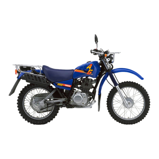
EAU00026 DESCRIPTION Left view 1. Headlight (page 6-29 ~ 6-30) 6. Shift pedal (page 3-4) 2. Fuel cock (page 3-7) 3. Fuse (For 12 V model) (page 6-28) 4. Tool kit (page 6-1) 5. Air filter (page 6-10) -
Page 17: Right View
DESCRIPTION Right view 7. Rear shock absorber spring preload 11. Fuse (page 6-27 ~ 6-28) adjuster (page 3-9) 8. Rear brake pedal (page 3-5) 9. Kick starter (page 3-8) 10. Battery (page 6-24 ~ 6-27) -
Page 18: Controls/Instruments
DESCRIPTION Controls/Instruments 12. Clutch lever (page 3-4, 6-15 ~ 6-16) 17. Starter (choke) “1” 13. Left handlebar switches (page 3-2 ~ 3-4) (For 12 V model) (page 3-8) 14. Starter (choke) 18. Right handlebar switches (page 3-2 ~ 3-4) (For 6 V model) (page 3-8) 19. -
Page 19: Instrument And Control Functions
EAU00027 INSTRUMENT AND CONTROL FUNCTIONS 1. Neutral indicator light “NEUTRAL” 1. Speedometer 2. Odometer EAU00028 EAU00056 Main switch Indicator light EAU00098 Speedometer The main switch controls the igni- The speedometer shows riding tion and lighting systems. Its oper- EAU00062 speed. Neutral indicator light “NEUTRAL”... -
Page 20: Handlebar Switches (For 6 V Model)
INSTRUMENT AND CONTROL FUNCTIONS EAU00131 Lights switch “LIGHTS” Turn the light switch to “ON” to turn on the headlight, taillight, and meter lights. EAU00128 Turn signal switch “TURN” This is a three-position switch. The center position is off. 1. Dimmer switch “LIGHTS” 1. -
Page 21: Handlebar Switches (For 12 V Model)
INSTRUMENT AND CONTROL FUNCTIONS EAU00127 Turn signal switch To signal a right-hand turn, push the switch to “6”. To signal a left- hand turn, push the switch to “4”. Once the switch is released it will return to the center position. To cancel the signal, push the switch in after it has returned to the center position. -
Page 22: Clutch Lever
INSTRUMENT AND CONTROL FUNCTIONS PUSH 1. Engine stop switch 1. Clutch lock lever 1. Shift pedal 2. Start switch “START” 2. Clutch lever N. Neutral EAU00156 EAU00157 EAU00141 Clutch lever Shift pedal Start switch “START” The clutch lever is located on the This motorcycle is equipped with a starter motor... -
Page 23: Front Brake Lever
INSTRUMENT AND CONTROL FUNCTIONS 1. Front brake lever 1. Rear brake pedal 1. Fuel tank cap EAU00158 EAU00162 EAU00179 Front brake lever Rear brake pedal Fuel tank cap The front brake lever is located on The rear brake pedal is on the right Remove the fuel tank cap by turn- the right handlebar. -
Page 24: Fuel
INSTRUMENT AND CONTROL FUNCTIONS EAU00185 EAU00192* Recommended fuel: Always wipe off spilled fuel imme- Regular unleaded gasoline diately with a dry and clean soft only cloth. Fuel may deteriorate painted Fuel tank capacity: surfaces or plastic parts. Total: 10.0 L (2.64 US gal) (2.20 Imp.gal) Reserve: 1. -
Page 25: Fuel Cock
INSTRUMENT AND CONTROL FUNCTIONS FUEL FUEL FUEL 1. Arrow mark 1. Arrow mark 1. Arrow mark EAU01121 Fuel cock With the lever in this position, fuel This indicates reserve. If you run The fuel cock supplies fuel from flows to the carburetor. Normal out of fuel while riding, move the the tank to the carburetor while fil- riding is done with the lever in this... -
Page 26: Starter (Choke) (For 6 V Model)
INSTRUMENT AND CONTROL FUNCTIONS 1. Starter (choke) 1. Starter (choke) “1” 1. Kickstarter EAU00211* EAU00210* EAU00212 Starter (choke) Starter (choke) “1” Kick starter (For 6 V model) (For 12 V model) Rotate the kick starter away from Starting a cold engine requires a Starting a cold engine requires a the engine. -
Page 27: Seat
INSTRUMENT AND CONTROL FUNCTIONS ×1, Right ×1) 1. Bolt (Left 1. Special wrench 2. Position indicator EAU00243 To install EAU00295* Seat Rear shock absorber adjustment 1. Insert the projections on the To remove front of the seat into the hold- This shock absorber is equipped 1. -
Page 28: Front And Rear Carriers
8 Do not deform or damage the cylinder in any way. Cylinder damage will result in poor damping performance. 8 Take your shock absorber to a Yamaha dealer for any service. 3-10... -
Page 29: Auxiliary Dc Terminal (For 12 V Model)
INSTRUMENT AND CONTROL FUNCTIONS AMPERAGE CHART IDLING SPEED HEAD/TAIL LIGHT “ON” 12V, 3A HEAD/TAIL LIGHT “OFF” 12V, 6A EC000028 If accessories are used in excess of the above capacity, or if acces- sories are used with the engine 1. Auxiliary DC terminal not running, the battery will lose 2. -
Page 30: Pre-Operation Checks
EAU01114 PRE-OPERATION CHECKS Owners are personally responsible for their vehicle’s condition. Your motorcycle’s vital functions can start to deteriorate quickly and unexpectedly, even if it remains unused (for instance, if it is exposed to the elements). Any damage, fluid leak or loss of tire pressure could have serious consequences. Therefore, it is very important that, in addition to a thorough visual inspection, you check the following points before each ride. - Page 31 PRE-OPERATION CHECKS ITEM CHECKS PAGE 9 Check fuel level. Fuel tank 3-5 ~ 3-6 9 Fill with fuel if necessary. Lights, signals and 9 Check for proper operation. 6-29 ~ 6-31 switches NOTE: Pre-operation checks should be made each time the motorcycle is used. Such an inspection can be accom- plished in a very short time;...
-
Page 32: Operation And Important Riding Points
(choke) turned off. should be on. If the light does not and death within a short time. come on, ask a Yamaha dealer to Always operate your motorcy- inspect it. cle in an area with adequate ventilation. -
Page 33: Starting And Warming Up A Cold Engine (For 12 V Model)
NOTE: back the starter (choke) to the When the transmission is in neu- warming up position (about tral, the neutral indicator light halfway). should be on. If the light does not come on, ask a Yamaha dealer to inspect it. -
Page 34: Starting A Warm Engine
OPERATION AND IMPORTANT RIDING POINTS EAU01258 EC000048 Starting a warm engine The starter (choke) is not required 8 Do not coast for long periods when the engine is warm. with the engine off, and do EC000046 not tow the motorcycle a long distance. -
Page 35: Tips For Reducing Fuel Consumption
OPERATION AND IMPORTANT RIDING POINTS EAU00424* EAU00436* EAU00445* Engine break-in Tips for reducing fuel 0 ~ 150 km (0 ~ 93 mi) There is never a more important consumption Avoid operation above 1/3 throttle. period in the life of your motorcy- Your motorcycle’s fuel consump- Stop the engine and let it cool for 5 cle than the period between zero... -
Page 36: Parking
EW000059 8 If any engine trouble should occur during the break-in peri- The muffler and exhaust pipe are od, consult a Yamaha dealer hot. Park the motorcycle in a place immediately. where pedestrians or children are not likely to touch the motorcycle. -
Page 37: Periodic Maintenance And Minor Repair
If you are not familiar with motor- motorcycle in the safest and most cycle service, this work should be efficient condition possible. Safety done by a Yamaha dealer. is an obligation of the motorcycle owner. The maintenance and lubri- cation schedule chart should be... - Page 38 Yamaha dealer for service. EW000063 Modifications to this motorcycle not approved by Yamaha may cause loss of performance, and render it unsafe for use. Consult a Yamaha dealer before attempting any changes.
-
Page 39: Periodic Maintenance And Lubrication
PERIODIC MAINTENANCE AND MINOR REPAIR EAU00473* PERIODIC MAINTENANCE AND LUBRICATION EVERY 6,000 km 12,000 km Initial (3,500 mi) or (7,000 mi) or ITEM CHECKS AND MAINTENANCE JOBS 1,000 km 6 months 12 months (600 mi) (Whichever (Whichever comes first) comes first) 9 Check fuel hoses for cracks or damage. - Page 40 PERIODIC MAINTENANCE AND MINOR REPAIR EVERY 6,000 km 12,000 km Initial (3,500 mi) or (7,000 mi) or ITEM CHECKS AND MAINTENANCE JOBS 1,000 km 6 months 12 months (600 mi) (Whichever (Whichever comes first) comes first) 9 Check swingarm pivoting point for play. √...
- Page 41 √ 9 Clean or replace if necessary. 21 * Engine oil strainer * Since these items require special tools, data and technical skills, they should be serviced by a Yamaha dealer. EAU00479 NOTE: The air filter needs more frequent service if you are riding in unusually wet or dusty areas.
-
Page 42: Panel Removal And Installation
PERIODIC MAINTENANCE AND MINOR REPAIR EAU01122 Panel removal and installation The panels illustrated need to be removed to perform some of the maintenance described this chapter. Refer to this section each time a panel has to be removed or rein- stalled. -
Page 43: Spark Plug Inspection
If a torque wrench is not available by a Yamaha dealer. The condition wire thickness gauge and adjust it when installing a spark plug, a of the spark plug can indicate the to specification. -
Page 44: Engine Oil
PERIODIC MAINTENANCE AND MINOR REPAIR 1. Level window 1. Oil filler cap 1. Drain plug 2. Maximum level mark 2. With engine stopped, Engine oil replacement 3. Minimum level mark check the oil level through the 1. Warm up the engine for a few EAU00517* Engine oil level window located at the... - Page 45 PERIODIC MAINTENANCE AND MINOR REPAIR 6. Clean the oil filter and strainer with solvent. Replace if neces- sary. 7. Check the O-rings. If damaged, replace. 8. Install the drain plug, filter cover, screws and drain bolt. Tighten the drain plug to the specified tightening torque.
-
Page 46: Air Filter
PERIODIC MAINTENANCE AND MINOR REPAIR EC000066 Tightening torque: Drain plug: 8 Do not put in any chemical 43 Nm (4.3 m0kgf, additives. Engine oil also lubri- 31.1 ft0lbf) cates the clutch and additives Filter cover screw: could cause clutch slippage. For 6 V model: 8 Be sure no foreign material 7 Nm (0.7 m0kgf,... -
Page 47: Carburetor Adjustment
The carburetor is a vital part of the engine and requires very sophisti- cated adjustment. Most adjust- ments should be left to a Yamaha dealer who has the professional knowledge and experience to do so. However, the following may be serviced by the owner as part of 1. -
Page 48: Idle Speed Adjustment
1,300 ~ 1,400 r/min Adjust the throttle cable by turning NOTE: the adjusting nut so that specified If the specified idle speed cannot free play at the throttle grip is be obtained by performing the obtained. above adjustment, consult Yamaha dealer. 6-12... -
Page 49: Valve Clearance Adjustment
This adjustment however, free play. motorcycle. should be left to a professional 3. Tighten the locknut. EW000091 Yamaha service technician. Tire inflation pressure should be checked and adjusted when the temperature of the tire equals the ambient air temperature. Cold tire pressure... - Page 50 (minimum a good quality replacement. tread depth), if the tire has a nail or glass fragments in it, or if the side wall is cracked, contact a Yamaha dealer immediately and have the tire replaced. 6-14...
-
Page 51: Wheels
If any 1. Adjusting bolt 2. Lock nut abnormal condition exists in a 3. Free play wheel, consult a Yamaha deal- EAU00694* er. Do not attempt even small Clutch lever free play repairs to the wheel. If a wheel... -
Page 52: Front Brake Lever Free Play Adjustment
PERIODIC MAINTENANCE AND MINOR REPAIR 1. Adjusting nut 1. Adjusting bolt 1. Adjusting nut 2. Lock nut 2. Locknut 2. Locknut 3. Free play If the specified free play cannot be 4. Loosen the locknut at the EAU00699* obtained, proceed with the follow- clutch lever. -
Page 53: Rear Brake Pedal Height And Free Play Adjustment
EW000104 increase free play or in direction b to decrease free play. It is advisable to have a Yamaha dealer make this adjustment. Pedal height The brake pedal should be posi- tioned so that its top end is approximately 10 mm (0.39 in) -
Page 54: Brake Light Switch Adjustment
If the indicator reach- brake light switch, hold the switch es to the wear limit line, ask a body so it does not rotate while Yamaha dealer to replace the turning the adjusting nut. shoes. Turn the adjusting nut in direction a to make the brake light come on earlier. -
Page 55: Drive Chain Slack Check
PERIODIC MAINTENANCE AND MINOR REPAIR Drive chain slack: 20 ~ 30 mm (0.79 ~ 1.18 in) If the drive chain slack is incorrect, adjust it as follows. a. Chain slack 1. Axle nut 2. Sprocket shaft nut EAU00744* 3. Chain adjusting plate Drive chain slack check EAU01274* Drive chain slack adjustment... -
Page 56: Drive Chain Lubrication
PERIODIC MAINTENANCE AND MINOR REPAIR EAU01106* 3. To tighten the chain, turn the Tightening torque: Drive chain lubrication chain adjusting plates in direc- Axle nut: The chain consists of many parts tion a. To loosen the chain, 85 Nm (8.5 m0kgf, which work with each other. -
Page 57: Cable Inspection And Lubrication
Lubricate the cables and cable with a suitable all-purpose grease. ends. If a cable does not operate smoothly, ask a Yamaha dealer to replace it. Recommended lubricant: Engine oil 6-21... -
Page 58: Brake And Clutch Lever Lubrication
Recommended lubricant: stand moves down Lithium-soap-based grease smoothly. Recommended lubricant: Lithium-soap-based grease 1. Grease nipple EAU00791* EW000113 Rear suspension lubrication Lubricate the pivoting parts. If the sidestand does not move smoothly, consult a Yamaha deal- Recommended lubricant: Lithium-soap-based grease 6-22... -
Page 59: Front Fork Inspection
If any smoothly. free play can be felt, ask a Yamaha dealer to inspect and adjust the EC000098 steering. Inspection is easier if the front wheel is removed. -
Page 60: Wheel Bearings
Check the level of the battery elec- so there is no danger of it falling turn smoothly, have a Yamaha trolyte and make sure that the ter- over. dealer inspect the wheel bearings. - Page 61 PERIODIC MAINTENANCE AND MINOR REPAIR EW000116 EC000100 Battery electrolyte is poisonous Normal tap water contains miner- and dangerous, causing severe als which are harmful to a battery; burns, etc. It contains sulfuric acid. therefore, refill only with distilled Avoid contact with skin, eyes or water.
-
Page 62: Battery (For 12 V Model)
8 If the battery seems to have discharged, consult a Yamaha 1. Battery 2. Breather pipe dealer. 8 If the motorcycle is equipped Battery storage... -
Page 63: Fuse Replacement (For 6 V Model)
Keep sparks, flame, cigarettes etc., circuit in question. Install a new Yamaha dealer. away. Ventilate when charging or 8 Always make sure the connec- fuse of proper amperage. Turn on using enclosed space. -
Page 64: Fuse Replacement (For 12 V Model)
Install a new fuse of proper amperage. Turn on the switches and see if the electrical Specified fuse: device operates. If the fuse imme- Main fuse: 20A diately blows again, consult a Auxiliary DC terminal fuse: Yamaha dealer. 6-28... -
Page 65: Replacing The Headlight Bulb
PERIODIC MAINTENANCE AND MINOR REPAIR For 6 V model For 12 V model 1. Screw 1. Screw 1. Leads (×3) 2. Bulb holder cover (For 12 V model) EAU01275 2. Disconnect the headlight leads Replacing the headlight bulb and remove the bulb holder If the headlight bulb burns out, cover. -
Page 66: Tail Light Bulb Replacement
1. Remove the screws and the 4. Remove the defective bulb. beam adjustment is necessary, lense. EW000119 ask a Yamaha dealer to make 2. Remove the defective bulb by that adjustment. Keep flammable products and your pushing it inward and turning it counterclockwise. -
Page 67: Turn Signal Light Bulb Replacement (For 6 V Model)
PERIODIC MAINTENANCE AND MINOR REPAIR For 12 V model For 6 V model For 12 V model 1. Bulb 1. Lense 1. Lense 2. Lense 2. Bulb 2. Bulb 3. Screw (×2) 3. Screw 3. Holder EAU01095* 3. Install a new bulb by pushing EAU01731* Turn signal light bulb Turn signal light bulb... -
Page 68: Supporting The Motorcycle
EAU01579 Rear wheel service Supporting the motorcycle Use a motorcycle stand or motor- Since the Yamaha AG200F has no cycle jack to elevate the motorcycle centerstand, follow these precau- so the rear wheel is off the ground. tions when removing the front and... -
Page 69: Front Wheel Installation
PERIODIC MAINTENANCE AND MINOR REPAIR 1. Brake cable 2. Axle nut EAU01687* 3. Install the wheel axle and the Front wheel installation 2. Loosen the brake cable free axle nut (make sure the slot in 1. Install the brake shoe plate play adjusting nuts and bolts. -
Page 70: Rear Wheel Removal
8 It is advisable to have a 5. Remove the wheel axle nut. Yamaha dealer service the 6. Pull out the axle. wheel. 7. Slide the wheel to the right 8 Securely support the motorcy-... -
Page 71: Rear Wheel Installation
If your motorcycle requires any specified torque repair, bring it to a Yamaha dealer. 5. Insert a new cotter pin. skilled technicians Yamaha dealership have the tools,... -
Page 72: Troubleshooting Chart (For 6 V Model)
2. Compression There is compression. Go to ignition check. Use the kick starter. No compression. Ask a Yamaha dealer to inspect. 3. Ignition Wipe clean with dry cloth and correct Open throttle half-way and start Wet. Remove spark spark gap or replace spark plug. -
Page 73: Troubleshooting Chart (For 12 V Model)
2. Compression There is compression. Go to ignition check. Use electric starter. No compression. Ask a Yamaha dealer to inspect. 3. Ignition Wipe clean with dry cloth and Open throttle half-way and start the Wet. Remove spark correct spark gap or replace spark plug. -
Page 74: Motorcycle Care And Storage
Be couplers connectors, are not all rust-resistant. While a sure to consult a Yamaha dealer including the spark plug cap, rusty exhaust pipe may remain for advice on what products to use are tightly installed. - Page 75 MOTORCYCLE CARE AND STORAGE 8 Improper cleaning can damage 8 Do Cleaning high-pressure After normal use windshields, cowlings, panels washers or steam-jet cleaners Remove dirt with warm water, a and other plastic parts. Use since they cause water seep- neutral detergent and a soft clean only a soft, clean cloth or age and deterioration in the sponge, then rinse with plenty of...
- Page 76 MOTORCYCLE CARE AND STORAGE After riding in the rain, near the After cleaning 8. Let the motorcycle dry com- sea or on salt-sprayed roads 1. Dry the motorcycle with a pletely before storing it or cov- Since sea salt or salt sprayed on chamois or an absorbing cloth.
-
Page 77: Storage
MOTORCYCLE CARE AND STORAGE Long-term Storage NOTE: Before storing your motorcycle for Short-term Consult Yamaha dealer several months: Always store your motorcycle in a advice on what products to use. 1. Follow all the instructions in cool, dry place and, if necessary, the “Care”... - Page 78 MOTORCYCLE CARE AND STORAGE a. Remove the spark plug cap 6. Lubricate all control cables and 9. Remove the battery and fully and spark plug. the pivoting points of all levers charge it. Store it in a cool, dry b. Pour a teaspoonful of engine and pedals as well as of the place and recharge it once a oil into the spark plug bore.
-
Page 79: Specifications (For 6 V Model)
EAU01038 SPECIFICATIONS Specifications (For 6 V model) Engine oil Model AG200F Type SAE 10W-30, SAE 10W-40, Dimensions SAE 15W-40, SAE 20W-40 or SAE 20W-50 Overall length 2,135 mm (84.1 in) -20 -10 10 20 30 40 50 ˚C Overall width 930 mm (36.6 in) - Page 80 SPECIFICATIONS Air filter Wet element Gear ratio 35/11 (3.181) Fuel 31/15 (2.066) Type Regular unleaded gasoline only 30/21 (1.428) Fuel tank capacity 10.0 L (2.64 US gal) 25/26 (0.961) (2.20 Imp.gal) 22/31 (0.709) Reserve amount 2.0 L (0.53 US gal) Chassis (0.44 Imp.gal) Frame type...
- Page 81 SPECIFICATIONS Tire air pressure (measured on cold tires): Rear suspension Loading condition 0 ~ 112 kg (0 ~ 247 lb) Type Swingarm (Monocross) Front 125 kPa (18 psi) (1.25 kgf/cm Spring/shock absorber type Coil spring/gas-oil damper Rear 150 kPa (22 psi) (1.50 kgf/cm Wheel travel 165.0 mm (6.50 in) *Load is total weight of cargo, rider and accessories.
-
Page 82: Specifications (For 12 V Model)
SPECIFICATIONS Specifications (For 12 V model) Engine oil Model AG200F/AG200FE Type SAE 10W-30, SAE 10W-40, Dimensions SAE 15W-40, SAE 20W-40 or SAE 20W-50 Overall length 2,160 mm (85.0 in) -20 -10 10 20 30 40 50 ˚C Overall width 930 mm (36.6 in) - Page 83 SPECIFICATIONS Air filter Wet element Gear ratio 35/11 (3.181) Fuel 31/15 (2.066) Type Regular unleaded gasoline only 30/21 (1.428) Fuel tank capacity 10.0 L (2.64 US gal) 25/26 (0.961) (2.20 Imp.gal) 22/31 (0.709) Reserve amount 2.0 L (0.53 US gal) Chassis (0.44 Imp.gal) Frame type...
- Page 84 SPECIFICATIONS Tire air pressure (measured on cold tires): Rear suspension Loading condition 0 ~ 112 kg (0 ~ 247 lb) Type Swingarm (Monocross) Front 125 kPa (18 psi) (1.25 kgf/cm Spring/shock absorber type Coil spring/gas-oil damper Rear 150 kPa (22 psi) (1.50 kgf/cm Wheel travel 165.0 mm (6.50 in) *Load is total weight of cargo, rider and accessories.
- Page 85 SPECIFICATIONS EAU01064 HOW TO USE THE CONVERSION TABLE CONVERSION TABLE All specification data in this manual are listed in SI METRIC TO IMPERIAL and METRIC UNITS. Metric unit Multiplier Imperial unit Use this table to convert METRIC unit data to m •...
-
Page 86: Consumer Information
Yamaha dealer or for reference in case the vehicle is stolen. 1. Key identification number 1. Key identification number 1. KEY IDENTIFICATION... -
Page 87: Vehicle Identification Number
Record this number in the space order spare parts from your provided. Yamaha dealer. NOTE: The vehicle identification number is used to identify your motorcycle and may be used to register your motorcycle with licensing... - Page 90 YAMAHA MOTOR CO., LTD. PRINTED ON RECYCLED PAPER PRINTED IN JAPAN 2007.12–0.9 × 1 !