
Related Manuals for U-Line WH95FC


Summary of Contents for U-Line WH95FC
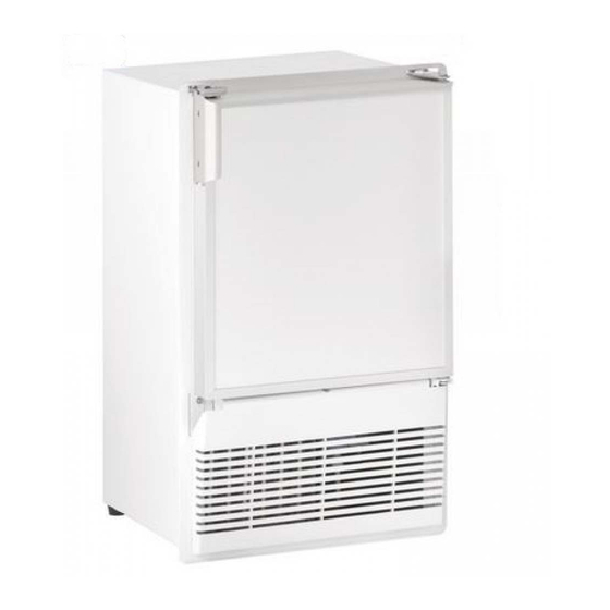
- Page 1 USER GUIDE SAFETY • INSTALLATION & INTEGRATION • OPERATING INSTRUCTIONS • MAINTENANCE • SERVICE RIGHT PRODUCT. RIGHT PLACE. RIGHT TEMPERATURE. SINCE 1962. Marine Series WH95FC 14" Crescent Ice Maker • •...
-
Page 2: Table Of Contents
USER GUIDE u-line.com SAFETY • INSTALLATION & INTEGRATION • OPERATING INSTRUCTIONS • MAINTENANCE • SERVICE Contents Service Extended Intro Wire Diagram Safety Product Liability Safety and Warning Warranty Claims Disposal and Recycling Ordering Replacement Parts System Diagnosis Guide Installation Compressor Specifications... - Page 3 1. U-Line Customer Care must be contacted immediately at +1.800.779.2547. 2. Service or repairs performed on the unit without prior written approval from U-Line is not permitted. If the unit has been altered or repaired in the field without prior written approval from U-Line, claims will not be eligible.
-
Page 4: Safety And Warning
USER GUIDE u-line.com SAFETY • INSTALLATION & INTEGRATION • OPERATING INSTRUCTIONS • MAINTENANCE • SERVICE Safety and Warning NOTICE Please read all instructions before installing, operating, or servicing the appliance. Use this appliance for its intended purpose only and follow... -
Page 5: Disposal And Recycling
USER GUIDE u-line.com SAFETY • INSTALLATION & INTEGRATION • OPERATING INSTRUCTIONS • MAINTENANCE • SERVICE Disposal and Recycling DANGER RISK OF CHILD ENTRAPMENT. Before you throw away your old refrigerator or freezer, take off the doors and leave shelves in place so children may not easily climb inside. -
Page 6: Environmental Requirements
USER GUIDE u-line.com SAFETY • INSTALLATION & INTEGRATION • OPERATING INSTRUCTIONS • MAINTENANCE • SERVICE Environmental Requirements This model is intended for indoor/interior applications only and is not to be used in installations that are open/ exposed to natural elements. - Page 7 USER GUIDE u-line.com SAFETY • INSTALLATION & INTEGRATION • OPERATING INSTRUCTIONS • MAINTENANCE • SERVICE Electrical WARNING SHOCK HAZARD — Electrical Grounding Required. Never attempt to repair or perform maintenance on the unit until the electricity has been disconnected. Never remove the round grounding prong from the plug and never use a two-prong grounding adapter.
-
Page 8: Cutout Dimensions
SAFETY • INSTALLATION & INTEGRATION • OPERATING INSTRUCTIONS • MAINTENANCE • SERVICE Cutout Dimensions PREPARE SITE Your U-Line product has been designed for either free- standing or built-in installation. When built-in, your unit does not require additional air space for top, sides, or rear. -
Page 9: Product Dimensions
USER GUIDE u-line.com SAFETY • INSTALLATION & INTEGRATION • OPERATING INSTRUCTIONS • MAINTENANCE • SERVICE Product Dimensions 17" (432 mm)* 25-1/16" (637 mm) 8 15/16" (227 mm) 14" (356 mm) *Add 1-1/2" For For Water Line Clearance Product Dimensions 1... -
Page 10: Water Hookup
The water valve uses a standard 1/4" (6.35 mm) is under pressure at all times. Plastic may crack compression fitting. U-Line recommends using accessory or rupture with age and cause damage to your water hook up kit – part # WATERHOOKUP. The kit home. - Page 11 USER GUIDE u-line.com SAFETY • INSTALLATION & INTEGRATION • OPERATING INSTRUCTIONS • MAINTENANCE • SERVICE 3. Locate water 6. Turn on water supply and check for leaks. valve in the front of the unit and 7. Reinstall the grille (plinth strip/base fascia) and access thread water panel (if equipped) along with the back panel.
-
Page 12: General Installation
USER GUIDE u-line.com SAFETY • INSTALLATION & INTEGRATION • OPERATING INSTRUCTIONS • MAINTENANCE • SERVICE General Installation INSTALLATION 1. Plug in the power/electrical cord. LEVELING INFORMATION 2. Gently push the unit into position. Be careful not to NOTICE entangle the cord and water line. -
Page 13: Grille / Plinth Installation
USER GUIDE u-line.com SAFETY • INSTALLATION & INTEGRATION • OPERATING INSTRUCTIONS • MAINTENANCE • SERVICE Grille - Plinth Installation REMOVING AND INSTALLING GRILLE WARNING Disconnect electric power to the unit before removing the grille. When using the unit, the grille (plinth strip/base fascia) must be installed. -
Page 14: Door Swing
Door Swing All units have a zero clearance for the door to open 90°. U-Line recommends a minimum door clearance of 3/4" (19 mm) to accommodate the handle if the unit is installed next to a wall or similar type of structure. -
Page 15: Door Adjust
USER GUIDE u-line.com SAFETY • INSTALLATION & INTEGRATION • OPERATING INSTRUCTIONS • MAINTENANCE • SERVICE Door Adjustments To reverse the door mounting, perform the following: CHECKING DOOR ALIGNMENT 1. Remove grille (see GRILLE-PLINTH INSTALLATION). The unit’s door is aligned at the factory before shipment. - Page 16 USER GUIDE u-line.com SAFETY • INSTALLATION & INTEGRATION • OPERATING INSTRUCTIONS • MAINTENANCE • SERVICE 6. Install hinge on opposite side at bottom of cabinet. 9. Remove plastic hole plug from door handle and Align hinge outer edge with cabinet before tightening relocate to opposite side.
- Page 17 USER GUIDE u-line.com SAFETY • INSTALLATION & INTEGRATION • OPERATING INSTRUCTIONS • MAINTENANCE • SERVICE 12.Remove all three screws on the opposite side of the 14.Place door on lower hinge pin. Invert and install upper hinge and carefully lift off the door latch assembly.
-
Page 18: Door Latch
USER GUIDE u-line.com SAFETY • INSTALLATION & INTEGRATION • OPERATING INSTRUCTIONS • MAINTENANCE • SERVICE Door Latch The door latch assembly included with your unit can be installed to prevent the door from opening when the vehicle is in motion. -
Page 19: First Use
USER GUIDE u-line.com SAFETY • INSTALLATION & INTEGRATION • OPERATING INSTRUCTIONS • MAINTENANCE • SERVICE First Use All U-Line controls are preset at the factory. Initial startup requires no adjustments. NOTICE U-Line recommends discarding the ice produced during the first two to three hours of operation to avoid possible dirt or scale that may dislodge from the water line. -
Page 20: Ice
USER GUIDE u-line.com SAFETY • INSTALLATION & INTEGRATION • OPERATING INSTRUCTIONS • MAINTENANCE • SERVICE CAUTION ICE MAKER OPERATION NEVER use an ice pick, knife or other sharp When the ice bucket is full, the ice making mechanism will instrument to separate cubes. Shake the ice shut off. - Page 21 USER GUIDE u-line.com SAFETY • INSTALLATION & INTEGRATION • OPERATING INSTRUCTIONS • MAINTENANCE • SERVICE ICE MAKER ADJUSTMENT 3. Turn the adjusting screw toward the minus (-) sign (clockwise) for smaller cubes or toward the plus (+) Ice Cube Thickness Adjustment sign (counterclockwise) for larger cubes.
-
Page 22: Airflow And Product Loading
USER GUIDE u-line.com SAFETY • INSTALLATION & INTEGRATION • OPERATING INSTRUCTIONS • MAINTENANCE • SERVICE Airflow and Product Loading NOTICE The unit requires proper airflow to perform at its highest efficiency. Do not block the front grille at any time, or the unit will not perform as expected. -
Page 23: Cleaning
® monthly. For best results use Claire Stainless Steel INTERIOR CLEANING Polish and Cleaner, which can be purchased from U-Line Disconnect power to the unit. Corporation (Part Number 173348). Comparable products are acceptable. Frequent cleaning will remove surface Clean the interior and all removed components using a contamination that could lead to rust. - Page 24 USER GUIDE u-line.com SAFETY • INSTALLATION & INTEGRATION • OPERATING INSTRUCTIONS • MAINTENANCE • SERVICE DEFROSTING NOTICE Manual Defrost Models DO NOT clean ice bucket using a dishwasher. The This unit is a manual defrost model and will require bucket is not dishwasher safe and will be damaged.
-
Page 25: Cleaning Condenser
USER GUIDE u-line.com SAFETY • INSTALLATION & INTEGRATION • OPERATING INSTRUCTIONS • MAINTENANCE • SERVICE Cleaning Condenser INTERVAL - EVERY SIX MONTHS To maintain operational efficiency, keep the front grille free of dust and lint, and clean the condenser when necessary. -
Page 26: Extended Non-Use
SAFETY • INSTALLATION & INTEGRATION • OPERATING INSTRUCTIONS • MAINTENANCE • SERVICE Extended Non-Use VACATION/HOLIDAY, PROLONGED SHUTDOWN For questions regarding winterization, please call U-Line at +1.800.779.2547. The following steps are recommended for periods of extended non-use: CAUTION 1. Remove all consumable content from the unit. -
Page 27: Troubleshooting
• Evaporator: Refrigerant flowing through an evaporator may sound like boiling liquid. BEFORE CALLING FOR SERVICE If you think your U-Line product is malfunctioning, read • Condenser Fan: Air moving through a condenser may the CONTROL OPERATION section to clearly understand be heard. - Page 28 USER GUIDE u-line.com SAFETY • INSTALLATION & INTEGRATION • OPERATING INSTRUCTIONS • MAINTENANCE • SERVICE Causes which affect the internal temperatures of Problem Possible Cause and Remedy the cabinet include: Product is Not Air temperature does not indicate product • Temperature setting.
- Page 29 God, such as fire, floods, wind, and U-Line product to be free from defects in materials and lightning; damages incurred or resulting from shipping, workmanship for a period of five years from the date of improper installation, unauthorized modification, or purchase.
- Page 30 7. If a product defect is discovered during the applicable warranty period, you must promptly notify either U-Line at 8900 N. 55th Street, Milwaukee, Wisconsin 53223 USA or at +1.800.779.2547 or the dealer from whom you purchased the product. In no event shall such notification be received later than 30 days after the expiration of the applicable warranty period.
-
Page 31: Wire Diagram
USER GUIDE u-line.com SAFETY • INSTALLATION & INTEGRATION • OPERATING INSTRUCTIONS • MAINTENANCE • SERVICE Wire Diagram Wire Diagram 1... -
Page 32: Product Liability
U-Line in an unaltered condition. The dealer would then be authorized to • When the unit is ready for pickup, contact U-Line at permanently replace the end-user’s product at no cost to +1.800.779.2547 and U-Line will make arrangements the end-user. -
Page 33: Warranty Claims
USER GUIDE u-line.com SAFETY • INSTALLATION & INTEGRATION • OPERATING INSTRUCTIONS • MAINTENANCE • SERVICE Warranty Claims warranty status. We also accept the following information to verify warranty status: The following information defines the parameters for filing a warranty claim: •... -
Page 34: Ordering Replacement Parts
Warranty parts will be shipped at no charge after U-Line confirms warranty status. Please provide the model, serial number, part number and part description. Some parts will require color or voltage information. -
Page 35: System Diagnosis Guide
USER GUIDE u-line.com SAFETY • INSTALLATION & INTEGRATION • OPERATING INSTRUCTIONS • MAINTENANCE • SERVICE System Diagnosis Guide REFRIGERATION SYSTEM DIAGNOSIS GUIDE System Suction Suction Compressor Condenser Capillary Evaporator Wattage Condition Pressure Line Discharge Tube Normal Normal Slightly below Very hot... -
Page 36: Compressor Specifications
USER GUIDE u-line.com SAFETY • INSTALLATION & INTEGRATION • OPERATING INSTRUCTIONS • MAINTENANCE • SERVICE Compressor Specifications DANGER OVERLOAD PROTECTOR Electrocution can cause death or serious injury. Burns from hot or cold surfaces can cause serious injury. Take precautions when servicing this unit. -
Page 37: Troubleshooting Extended
USER GUIDE u-line.com SAFETY • INSTALLATION & INTEGRATION • OPERATING INSTRUCTIONS • MAINTENANCE • SERVICE Troubleshooting - Extended SPECIFIC ERRORS & ISSUES CAUTION Never attempt to repair or perform maintenance on the unit until the main electrical power has been disconnected from the unit. - Page 38 USER GUIDE u-line.com SAFETY • INSTALLATION & INTEGRATION • OPERATING INSTRUCTIONS • MAINTENANCE • SERVICE Concern Potential Causes Suggested Remedy Power cord not plugged in. Plug in power cord. Not freezing (compressor On/Off switch in off position. Turn switch to on position.
- Page 39 USER GUIDE u-line.com SAFETY • INSTALLATION & INTEGRATION • OPERATING INSTRUCTIONS • MAINTENANCE • SERVICE ICE MAKER DIAGNOSIS FLOW CHART DOES THE UNIT REFRIGERATE? Sealed System Leak Low Voltage Electrical Failure Voltage Drop Compressor Failure Wiring Fan Motor Failure Defrost System Failure...
-
Page 40: Freeze Cycle
USER GUIDE u-line.com SAFETY • INSTALLATION & INTEGRATION • OPERATING INSTRUCTIONS • MAINTENANCE • SERVICE ICE MAKER OPERATING CYCLES Freeze Cycle • Temperature control terminals 2 and 3 are closed. • Power to the condenser. • Power to the condenser fan. - Page 41 USER GUIDE u-line.com SAFETY • INSTALLATION & INTEGRATION • OPERATING INSTRUCTIONS • MAINTENANCE • SERVICE Harvest-1 Cycle • Temperature control terminals 2 and 3 are open - 2 and 1 close. • No power to the compressor or condenser fan.
- Page 42 USER GUIDE u-line.com SAFETY • INSTALLATION & INTEGRATION • OPERATING INSTRUCTIONS • MAINTENANCE • SERVICE HARVEST-2 CYCLE • Ice maker ejector blades reach approximately 2:00 position and cam depresses the hold switch. Power goes through the hold switch to the ice maker motor and mold heater.
- Page 43 USER GUIDE u-line.com SAFETY • INSTALLATION & INTEGRATION • OPERATING INSTRUCTIONS • MAINTENANCE • SERVICE WATER FILL CYCLE • Ice maker ejector blades reach approximately 10:00 position and cam depresses the water fill switch. • Power to the water valve. Ice maker mold fills.
- Page 44 USER GUIDE u-line.com SAFETY • INSTALLATION & INTEGRATION • OPERATING INSTRUCTIONS • MAINTENANCE • SERVICE TEMPERATURE CONTROL SPECIFICATIONS Double Throw Ice Maker Thermostat Numbers 4548, AR-19-12, 2636, 2690, 2691, 2717, 2783, 2782-S, 2763-S, 2780, 80-26005-02 These temperature controls are double throw, single pole controls.
- Page 45 USER GUIDE u-line.com SAFETY • INSTALLATION & INTEGRATION • OPERATING INSTRUCTIONS • MAINTENANCE • SERVICE LIMIT SWITCH SPECIFICATIONS • Normally closed Bi-metal switch • Open temperature: 104°F • Close temperature: 83°F The function of this switch is to open in the event of an overheating condition.
- Page 46 USER GUIDE u-line.com SAFETY • INSTALLATION & INTEGRATION • OPERATING INSTRUCTIONS • MAINTENANCE • SERVICE REPLACING ICE MAKER ASSEMBLY (CO29F 8. Remove ice maker assembly. ONLY) 1. Unplug the unit from the main power source. 9. Place new ice maker assembly into position and secure with three screws (5).
- Page 47 USER GUIDE u-line.com SAFETY • INSTALLATION & INTEGRATION • OPERATING INSTRUCTIONS • MAINTENANCE • SERVICE REPLACING ICE MAKER ASSEMBLY (ALL MODELS 17.Mount the back panel. EXCEPT CO29F) 1. Remove back panel. 18.Plug in unit and test. 2. Disconnect all wires at bell connectors (5 wires-Models 220 Volt Conversion List BI95, BI98 or SP18;...
-
Page 48: Defrost
USER GUIDE u-line.com SAFETY • INSTALLATION & INTEGRATION • OPERATING INSTRUCTIONS • MAINTENANCE • SERVICE Defrost These units are manual defrost. To defrost unit remove ice bucket. Turn unit off. Use toweling inside to absorb water as it melts down. This will help prevent water from getting onto customer’s floor. -
Page 49: Replace Ice Maker
USER GUIDE u-line.com SAFETY • INSTALLATION & INTEGRATION • OPERATING INSTRUCTIONS • MAINTENANCE • SERVICE Replace Ice Maker INSTALL ICE MAKER 1. If ice maker sits on evaporator (as shown) be sure to The new ice maker assembly you have received will have apply the included Alumilastic paste.