Sony D-F181 Service Manual
Fm/am compact disc compact player
Hide thumbs
Also See for D-F181:
- Operating instructions (2 pages) ,
- Operating instructions manual (11 pages) ,
- Operating instructions (2 pages)
Advertisement
D-F180AN/F181/F400/F411/F415
QQ
3 7 63 1515 0
SERVICE MANUAL
Ver 1.0 1998.06
TE
L 13942296513
Radio section
Frequency range
• AEP, UK, French, Saudi Arabia model:
FM: 87.5 – 108.0MHz
AM: 531 – 1,602kHz
• Except AEP, UK, French, Saudi Arabia, Tourist
model:
(STEP switch)
9kHz step:
FM: 87.5 – 108.0MHz
AM: 531 – 1,710kHz
10kHz step:
FM: 87.5 – 108.0MHz
AM: 530 – 1,710kHz
• Tourist model:
(STEP switch)
9kHz step:
FM: 76.0 – 108.0MHz
AM: 531 – 1,710kHz
10kHz step:
FM: 87.5 – 108.0MHz
AM: 530 – 1,710kHz
Antenna
FM: Headphones/earphones cord antenna
AM: Built-in ferrite bar antenna
www
.
MICROFILM
http://www.xiaoyu163.com
General
Power requirements
For the area code of the model you purchased,
upper left side of the bar cord on the package.
• Sony BP-DM10 Rechargeable battery: 2.4V
DC, Ni-Cd, 650mAh
Sony BP-DM20 Rechargeable battery: 2.4V
DC, Ni-MH, 1,200mAh
• Two LR6 (size AA) batteries: 3V DC
• AC power adaptor (DC IN 4.5V jack):
US/Canadian/E92 model: 120V, 60Hz
AEP/E13/Argentine model:
220 – 230V, 50/60Hz
UK model: 230 – 240V, 50Hz
Saudi Arabia model: 110 – 240V, 50/60Hz
Australian model: 240V, 50Hz
Tourist, E33 model: 100 – 240V, 50/60Hz
Hong Kong model: 220V, 50/60Hz
Chinese model: 220V, 50Hz
• Sony CPM-300P mount plate for use on car
battery: 4.5V DC
Dimensions (w/h/d) (without projecting parts and
controls)
Approx. 133 × 33 × 152mm (5
FM/AM COMPACT DISC COMPACT PLAYER
x
ao
u163
y
i
http://www.xiaoyu163.com
2 9
8
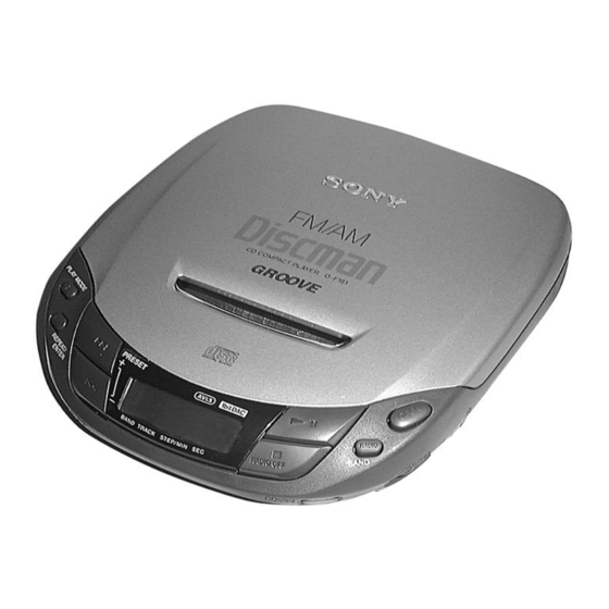
Photo : D-F181
Model Name Using Similar Mechanism
Q Q
3
CD Mechanism Type
6 7
1 3
1 5
Optical Pick-up Name
SPECIFICATIONS
check the
× 1
× 6 in.)
1
/
5
/
4
16
co
.
9 4
2 8
US Model
Canadian Model
AEP Model
D-F180AN/F181/F411
UK Model
E Model
Australian Model
D-F181/F411/F415
Chinese Model
Tourist Model
D-180AN/180ANC/181/
181C/181V/182CK/183
0 5
8
2 9
CDM-2811AAA
9 4
2 8
DAX-01A
Mass (without rechargeable battery)
Approx. 260g (9.2oz)
Operating temperature
5°C – 35°C (41°F – 95°F)
Supplied accessories
For the area code of the model you purchased,
upper left side of the bar cord on the package.
D-180AN
Earphones (1)
Connecting cord (Phono plug × 2 ↔ stereo
miniplug) (1)
D-F181
AC power adaptor (1)
AC plug adaptor (1)*
Earphones (1)
Connecting cord (Phono plug × 2 ↔ stereo
miniplug) (1)
* Supplied with E33, E13 and Saudi Arabia
models
— Continued on next page —
m
9 9
D-F411/F415
D-F181/F411
D-F181/F411
D-F411/F415
D-F400
9 9
check the
Advertisement
Chapters

Related Manuals for Sony D-F181


Summary of Contents for Sony D-F181
-
Page 1: Te L 13942296513
10kHz step: * Supplied with E33, E13 and Saudi Arabia FM: 87.5 – 108.0MHz Chinese model: 220V, 50Hz models • Sony CPM-300P mount plate for use on car AM: 530 – 1,710kHz Antenna battery: 4.5V DC FM: Headphones/earphones cord antenna... - Page 2 CRITIQUES POUR LA SÉCURITÉ DE FONCTIONNEMENT. NE COMPONENTS WITH SONY PARTS WHOSE PART NUMBERS REMPLACER CES COMPOSANTS QUE PAR DES PIÈSES SONY APPEAR AS SHOWN IN THIS MANUAL OR IN SUPPLEMENTS DONT LES NUMÉROS SONT DONNÉS DANS CE MANUEL OU PUBLISHED BY SONY.
-
Page 3: Table Of Contents
http://www.xiaoyu163.com SECTION 1 SERVICING NOTES 3 7 63 1515 0 TABLE OF CONTENTS 1. SERVICING NOTES ······················································· 3 NOTES ON HANDLING THE OPTICAL PICK-UP BLOCK OR BASE UNIT 2. GENERAL ·········································································· 5 The laser diode in the optical pick-up block may suffer electrostatic 3. - Page 4 http://www.xiaoyu163.com 3 7 63 1515 0 Precautions for Checking Emission of Laser Diode [MAIN BOARD] (Conductor side) Laser light of the equipment is focused by the object lens in the optical pick-up so that the light focuses on the reflection surface of the disc.
-
Page 5: General
http://www.xiaoyu163.com SECTION 2 GENERAL 3 7 63 1515 0 LOCATION AND FUNCTION OF CONTROLS 9 !º !¡ !™ !£ !¢ !∞ !§ !¶ !• !ª @º L 13942296513 1 DX/LOCAL (US, Canadian, E92) !º DC IN 4.5V jack !¡ HOLD switch MONO/STEREO !™... -
Page 6: Disassembly
http://www.xiaoyu163.com SECTION 3 DISASSEMBLY 3 7 63 1515 0 Note : Disassemble the unit in the order as shown below. LID ASSY, UPPER MD ASSEMBLY MAIN BOARD Note : Follow the disassembly procedure in the numerical order given. 3-1. LID ASSY, UPPER Lid assy, upper 1 OPEN L 13942296513... -
Page 7: Main Board
http://www.xiaoyu163.com 3 7 63 1515 0 3-3. MAIN BOARD S803 Main board S804 S301 When installing main board, position the knobs and the switches respectively. Cabinet (lower) sub assy L 13942296513 u163 — 7 — http://www.xiaoyu163.com... -
Page 8: Service Mode
http://www.xiaoyu163.com SECTION 4 SERVICE MODE 3 7 63 1515 0 Service Mode (service program) • Step 3 (Resetting service mode ) The equipment is provided with a service program built in the 1. Be sure to disconnect the external power supply and remove microcomputer, like conventional models. -
Page 9: Adjustments
http://www.xiaoyu163.com SECTION 5 ADJUSTMENTS 3 7 63 1515 0 CD SECTION Focus Bias Check Condition : • Hold the set in horizontal state. Precautions for Adjustment 1. Before beginning adjustment, set the equipment to service mode. Procedure : After the completion of adjustment, be sure to reset the service mode. - Page 10 http://www.xiaoyu163.com 3 7 63 1515 0 Focus/Tracking Gain Adjustment 1. Place the optical pick-up level, horizontally. (If the optical pick- A servo analyzer is necessary in order to perform this adjustment up is not level, the 2-axis device will be weighted and adjustment exactly.
- Page 11 http://www.xiaoyu163.com 3 7 63 1515 0 Adjustment Location : (Tuning voltage) digital voltmeter [MAIN BOARD] (Side A) TP41 (VT OUT) – • Repeat the procedures in each adjustment several times, and the frequency coverage and tracking adjustment should be finally done by the trimmer capacitors.
- Page 12 http://www.xiaoyu163.com 3 7 63 1515 0 Adjustment Location: [MAIN BOARD] (Side A) TP11 TP41 (ANT) (VT OUT) AM tracking adjustment AM voltage adjustment L 13942296513 FM voltage adjustment FM tracking adjustment u163 — 12 — http://www.xiaoyu163.com...
-
Page 13: Diagrams
http://www.xiaoyu163.com SECTION 6 DIAGRAMS 3 7 63 1515 0 6-1. IC PIN FUNCTION DISCRIPTION • IC1 µPC17072GB-552-1A7 Pin No. Pin Name Description Unused Unused TUMUTE H: mute on serial clock to EEPROM AMCTRL AM/FM band control. L-FM, H-AM EEPROM chip select L/O-SW pin 54 :- H: LINE OUT L: TUREQ IF-REQ... - Page 14 http://www.xiaoyu163.com 3 7 63 1515 0 Pin No. Pin Name Description VDD (VCPU) — positive power supply DRV MUTE O DRV not used (open) XGROOVE 0-DBB “L”: Headphones IC bass enable XLT-O-ESP latch output terminal for ESP “H”: latch. PWRSW-O-H/P power switch of headphones “H”: headphones power on AMUTE-O-HP analog mute control output terminal “H”: mute...
- Page 15 http://www.xiaoyu163.com 3 7 63 1515 0 Pin No. Pin Name Description NOT USED VREFH (VCPU-REF) A/D port positive power supply reference VREFL (GND-REF) A/D port ground reference AD-I-ESPSL/TEST ESP selector/test AD-I-KEY A/D input terminal for main unit key AD-I-WRMT A/D input terminal for remote control key AD-I-HI-DC A/D input terminal for DC in voltage detection AD-I-BAT...
-
Page 16: Printed Wiring Boards
http://www.xiaoyu163.com D-F180AN/F181/F400/F411/F415 6-2. PRINTED WIRING BOARD • Waveform • Semiconductor Location Ref. No. Location Ref. No. Location IC502 &ª SERVICE MODE IC301 !§ LOCAL : US/CANADIAN/E92/ARGENTINE C-14 D-11 MAIN BOARD MAIN BOARD during TRK servo OFF (COMPONENT SIDE) (CONDUCTOR SIDE) B-15 B-10 MONO... -
Page 17: Schematic Diagram - Cd Section
http://www.xiaoyu163.com D-F180AN/F181/F400/F411/F415 6-3. SCHEMATIC DIAGRAM — CD SECTION — • Refer to page 16 for Waveform. Note on Schematic Diagram: • All capacitors are in µF unless otherwise noted. pF: µµF 50 WV or less are not indicated except for electrolytics and tantalums. -
Page 18: Schematic Diagram - Tuner Section
http://www.xiaoyu163.com D-F180AN/F181/F400/F411/F415 6-4. SCHEMATIC DIAGRAM — TUNER SECTION — 6-5. IC BLOCK DIAGRAMS IC301 TC9438FNEL DATA MICRO COMPUTER INTERFASE INTERFASE CIRCUIT CIRCUIT TIMING DINAMIC GENERATOR BASS BOOST CIRCUIT DIGITAL FILTER CIRCUIT DEEMPHASIS FILTER CIRCUIT ATTENUATER OPERATIONAL CIRCUIT Σ-∆ MODULATION CIRCUIT OUTPUT OUTPUT CIRCUIT... - Page 19 http://www.xiaoyu163.com D-F180AN/F181/F400/F411/F415 3 7 6 3 1 5 1 5 0 IC401 MPC18A26VMEL IC502 BU9325KS INM3 ERROR DC IN DETECT DCDT AVDD C1FX TIMING ERROR INTERPOLATION DCIN GENERATOR CORRECTION C2FX ERROR AMP OFFSET CHARGE SW INM2 CHGSW EY E C2F3 AD JO PWM2 C2F4...
-
Page 20: Block Diagram - Tuner Section
http://www.xiaoyu163.com D-F180AN/F181/F400/F411/F415 6-6. BLOCK DIAGRAM — TUNER SECTION — 3 7 6 3 1 5 1 5 0 FM ANT LINE AMP FM /AM B.P.F L OUT 1 FM IF TU L IF/RF AMP Q21,22 DBB/ XOFF 10.7MHz US,CANADIAN,E92,ARGENTINE 23 FM RF FM MIX 3 FM IF AM FERRITE-ROD... -
Page 21: Block Diagram - Cd Section
http://www.xiaoyu163.com D-F180AN/F181/F400/F411/F415 6-7. BLOCK DIAGRAM — CD SECTION — 3 7 6 3 1 5 1 5 0 • R-CH is omitted • Signal Path F180/F181 R551 OPTICAL R552 : FM PICK-UP BLOCK R553 (CDM-2811AAA) IC501 R-CH J301 RF AMP : CD LINE OUT F400/F410/F415... -
Page 22: Exploded Views
http://www.xiaoyu163.com SECTION 7 EXPLODED VIEWS 3 7 63 1515 0 NOTE: • -XX, -X mean standardized parts, so they may • The mechanical parts with no reference number When indicating parts by reference number, have some differences from the original one. in the exploded views are not supplied. -
Page 23: Optical Pick-Up Section
http://www.xiaoyu163.com 3 7 63 1515 0 7-2. OPTICAL PICK-UP SECTION M902 M901 S901 L 13942296513 Ref. No. Part No. Description Remarks Ref. No. Part No. Description Remarks A-3303-970-A SCREW ASSY, FEED ! 59 X-4946-311-1 OPTICAL PICK-UP (DAX-01A) 3-318-203-11 SCREW (B1.7 × 6), TAPPING 4-972-165-01 RACK 1-690-530-81 LEAD (WITH CONNECTOR) 4-973-631-01 SCREW... -
Page 24: Electrical Parts List
http://www.xiaoyu163.com SECTION 8 MAIN ELECTRICAL PARTS LIST 3 7 63 1515 0 • RESISTORS NOTE: • Due to standardization, replacements in the parts list may be different from the parts All resistors are in ohms. When indicating parts by reference number, specified in the diagrams or the components METAL: metal-film resistor please include the board name. - Page 25 http://www.xiaoyu163.com MAIN 3 7 63 1515 0 Ref. No. Part No. Description Remarks Ref. No. Part No. Description Remarks 1-165-176-11 CERAMIC CHIP 0.047uF C204 1-162-953-11 CERAMIC CHIP 100PF (F180/F181: AEP, UK, FR, EA/F400/F411/F415) C206 1-162-964-11 CERAMIC CHIP 0.001uF 1-164-346-11 CERAMIC CHIP (F180/F181: EXCEPT FR/F400/F411: EXCEPT FR/F415) 1-164-156-11 CERAMIC CHIP 0.1uF...
- Page 26 http://www.xiaoyu163.com MAIN 3 7 63 1515 0 Ref. No. Part No. Description Remarks Ref. No. Part No. Description Remarks C500 1-107-826-11 CERAMIC CHIP 0.1uF C805 1-115-156-11 CERAMIC CHIP (F400/F411/F415) C806 1-164-346-11 CERAMIC CHIP C501 1-162-917-11 CERAMIC CHIP 15PF C807 1-115-156-11 CERAMIC CHIP C503 1-162-970-11 CERAMIC CHIP 0.01uF...
- Page 27 http://www.xiaoyu163.com MAIN 3 7 63 1515 0 Ref. No. Part No. Description Remarks Ref. No. Part No. Description Remarks D304 8-719-992-02 DIODE RB705D IC304 8-759-082-60 IC TC7S66FU D305 8-719-941-86 DIODE DAN202U IC401 8-759-483-61 IC MPC18A26VMEL D306 8-719-420-90 DIODE MA8051-M (F181:FR/F411:FR) IC501 8-759-432-83 IC BA6386K D400...
- Page 28 http://www.xiaoyu163.com MAIN 3 7 63 1515 0 Ref. No. Part No. Description Remarks Ref. No. Part No. Description Remarks < TRANSISTOR > Q406 8-729-028-97 TRANSISTOR DTC114TUA-T106 Q407 8-729-028-74 TRANSISTOR DTA114TUA-T106 8-729-102-07 TRANSISTOR 2SC2223-F13 Q500 8-729-029-06 TRANSISTOR DTC124EUA-T106 (F181: CND, E92/F411: US, CND, E92, AR/ (F400/F411/F415) F415: US, AR) Q501...
- Page 29 http://www.xiaoyu163.com MAIN 3 7 63 1515 0 Ref. No. Part No. Description Remarks Ref. No. Part No. Description Remarks 1-216-839-11 METAL CHIP 1/16W 1-216-830-11 METAL CHIP 5.6K 1/16W (F400) 1-216-833-11 METAL CHIP 1/16W 1-216-841-11 METAL CHIP 1/16W 1-216-838-11 METAL CHIP 1/16W (EXCEPT F400) 1-216-853-11 METAL CHIP...
- Page 30 http://www.xiaoyu163.com MAIN 3 7 63 1515 0 Ref. No. Part No. Description Remarks Ref. No. Part No. Description Remarks R307 1-216-864-11 METAL CHIP 1/16W R509 1-216-836-11 METAL CHIP 1/16W R308 1-216-864-11 METAL CHIP 1/16W R510 1-216-821-11 METAL CHIP 1/16W R310 1-216-142-00 RES,CHIP 1/8W R511...
- Page 31 http://www.xiaoyu163.com MAIN 3 7 63 1515 0 Ref. No. Part No. Description Remarks Ref. No. Part No. Description Remarks R603 1-216-864-11 METAL CHIP 1/16W R827 1-216-857-11 METAL CHIP 1/16W (F400/F411/F415) R828 1-216-833-11 METAL CHIP 1/16W R605 1-216-821-11 METAL CHIP 1/16W (F400/F411/F415) (F400/F411/F415) R829...
- Page 32 http://www.xiaoyu163.com 3 7 63 1515 0 Ref. No. Part No. Description Remarks Ref. No. Part No. Description Remarks MISCELLANEOUS 3-862-894-41 MANUAL, INSTRUCTION (POTUGUESE) (F181: E92) *************** 3-862-895-11 MANUAL, INSTRUCTION (SPANISH) 1-690-530-81 LEAD (WITH CONNECTOR) (F411: AEP) 1-660-965-11 PC BOARD, SLIDE FLEXIBLE 3-862-895-21 MANUAL, INSTRUCTION (ENGLISH) ! 59 X-4946-311-1 OPTICAL PICK-UP (DAX-01A)
- Page 33 D-F180AN/F181/F400/F411/F415 3 7 63 1515 0 L 13942296513 u163 Sony Corporation 98F1691-1 Printed in Japan ©1998.6 Personal A&V Products Company 9-924-938-11 Published by Quality Engineering Dept. — 48 — (Shibaura) http://www.xiaoyu163.com...
- Page 34 D-F400 Subject : Printed wiring board suffix change MAIN board -11 → -21 • Target models • D-F181 (Canadian, E92 models) L 13942296513 • D-F411 (US, Canadian, E92, Argentina models) • D-F415 (US, Argentina models) This service manual supplement-2 shows the schematic diagram and printed wiring board of with suffix-21.
- Page 35 CRITIQUES POUR LA SÉCURITÉ DE FONCTIONNEMENT. NE COMPONENTS WITH SONY PARTS WHOSE PART NUMBERS REMPLACER CES COMPOSANTS QUE PAR DES PIÈSES SONY APPEAR AS SHOWN IN THIS MANUAL OR IN SUPPLEMENTS DONT LES NUMÉROS SONT DONNÉS DANS CE MANUEL OU PUBLISHED BY SONY.
-
Page 36: Block Diagram - Tuner Section
http://www.xiaoyu163.com 1-1. BLOCK DIAGRAMS – TUNER SECTION – 1-2. IC BLOCK DIAGRAM FM ANT IC2 TA2111F-(EL) • Waveform LINE AMP IC502 &ª SERVICE MODE IC301 !§ FM /AM B.P.F during TRK servo OFF 1 FM IF IF/RF AMP L OUT TU L Q21,22 DBB/... -
Page 37: Printed Wiring Board
http://www.xiaoyu163.com D-F180AN/F181/F400/F411/F415 1-3. PRINTED WIRING BOARD • Semiconductor Location Ref. No. Location Ref. No. Location B-14 D-11 B-15 B-10 A-16 D-11 C-10 F-17 F-17 F-17 F-17 D101 I-19 B-16 D102 F-14 B-16 D201 I-19 F-22 D202 G-14 D301 E-14 D302 H-19 D303 D304... -
Page 38: Schematic Diagram - Cd Section
http://www.xiaoyu163.com D-F180AN/F181/F400/F411/F415 1-4. SCHEMATIC DIAGRAM — CD SECTION — • Refer to page 6 for Waveform and note on Schematic Diagram. w w w — 11 — — 12 — — 13 — — 14 — http://www.xiaoyu163.com... -
Page 39: Schematic Diagram - Tuner Section
http://www.xiaoyu163.com D-F180AN/F181/F400/F411/F415 1-5. SCHEMATIC DIAGRAM — TUNER SECTION — • Refer to page 7 for MAIN BOARD Printed Wiring Board. Note on Schematic Diagram: • All capacitors are in µF unless otherwise noted. pF: µµF 50 WV or less are not indicated except for electrolytics and tantalums. -
Page 40: Electrical Parts List
http://www.xiaoyu163.com MAIN 2. ELECTRICAL PARTS LIST 3 7 63 1515 0 NOTE: • Due to standardization, replacements in the • CAPACITORS: • COILS parts list may be different from the parts uF: µF uH: µH specified in the diagrams or the components •... - Page 41 http://www.xiaoyu163.com MAIN 3 7 63 1515 0 Ref. No. Part No. Description Remarks Ref. No. Part No. Description Remarks 1-115-467-11 CERAMIC CHIP 0.22uF C428 1-164-346-11 CERAMIC CHIP 1-164-227-11 CERAMIC CHIP 0.022uF C432 1-115-156-11 CERAMIC CHIP 1-162-965-11 CERAMIC CHIP 0.0015uF 10% C439 1-162-970-11 CERAMIC CHIP 0.01uF...
- Page 42 http://www.xiaoyu163.com MAIN 3 7 63 1515 0 Ref. No. Part No. Description Remarks Ref. No. Part No. Description Remarks C802 1-162-964-11 CERAMIC CHIP 0.001uF < FERRITE BEAD > (F411/F415) C804 1-162-970-11 CERAMIC CHIP 0.01uF FB11 1-216-864-11 METAL CHIP 1/16W C805 1-115-156-11 CERAMIC CHIP FB101 1-500-444-11 FERRITE...
- Page 43 http://www.xiaoyu163.com MAIN 3 7 63 1515 0 Ref. No. Part No. Description Remarks Ref. No. Part No. Description Remarks < COIL > 8-729-028-99 TRANSISTOR DTC114YUA-T106 8-729-231-74 TRANSISTOR 2SC4116-GL 1-416-547-11 COIL (WITH CORE) 8-729-028-97 TRANSISTOR DTC114TUA-T106 1-416-548-11 COIL (WITH CORE) 8-729-028-97 TRANSISTOR DTC114TUA-T106 X-4949-673-1 ANTENNA ASSY, HOLDER 8-729-026-53 TRANSISTOR 2SA1576A-T106-QR 1-411-989-11 COIL (WITH CORE) (AM OSC)
- Page 44 http://www.xiaoyu163.com MAIN 3 7 63 1515 0 Ref. No. Part No. Description Remarks Ref. No. Part No. Description Remarks 1-216-845-11 METAL CHIP 100K 1/16W R202 1-216-845-11 METAL CHIP 100K 1/16W 1-216-833-11 METAL CHIP 1/16W R203 1-216-841-11 METAL CHIP 1/16W 1-216-833-11 METAL CHIP 1/16W R205 1-216-821-11 METAL CHIP...
- Page 45 http://www.xiaoyu163.com MAIN 3 7 63 1515 0 Ref. No. Part No. Description Remarks Ref. No. Part No. Description Remarks R508 1-216-833-11 METAL CHIP 1/16W R605 1-216-821-11 METAL CHIP 1/16W R509 1-216-836-11 METAL CHIP 1/16W (F411/F415) R510 1-216-821-11 METAL CHIP 1/16W R606 1-216-821-11 METAL CHIP 1/16W...
- Page 46 http://www.xiaoyu163.com MAIN 3 7 63 1515 0 Ref. No. Part No. Description Remarks Ref. No. Part No. Description Remarks 1-692-014-11 SWITCH, KEY BOARD (=) 1-692-014-11 SWITCH, KEY BOARD (TUNING-,REPEAT/ENTER) 1-692-014-11 SWITCH, KEY BOARD (TUNING+,PLAY MODE) 1-771-482-11 SWITCH, KEY BOARD (MEMORY/ESP) 1-572-922-11 SWITCH, SLIDE (9K/10K) 1-572-922-11 SWITCH, SLIDE (DX/LOCAL) S301...
- Page 47 D-F180AN/F181/F400/F411/F415 3 7 63 1515 0 L 13942296513 u163 Sony Corporation 99A1692-1 Printed in Japan ©1999.1 Personal A&V Products Company 9-924-938-82 Published by Quality Engineering Dept. — 26 — (Shibaura) http://www.xiaoyu163.com...