Advertisement
Quick Links
U.S.
T 855 536 3573
F 561 998 6224
Asia
T 65 6424 7932
F 65 6424 7978
Australia
T 61 3 9239 1200
F 61 3 9239 1299
Canada
T 800 267 6317
F 613 737 5517
EMEA
T 48 58 326 22 40
F 48 58 326 22 41
Latin America
T 503 589 8614
F 561 994 6572
www.utcfireandsecurity.com
© 2012 UTC Fire & Security. All rights reserved.
UTC Fire & Security, 9 Farm Springs Road,
Farmington, CT 06034-4065, USA
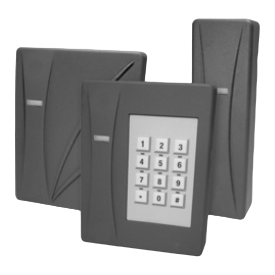
Description
Transition™ multi-technology card readers feature
simultaneous compatibility with multi-vendor 125 kHz
Proximity, Mifare (ISO 14443A), and Vicinity (ISO 15693)
credential technologies—all in one reader. With this
remarkable technology combination, security
administrators can now deploy the Transition readers into
new or existing facilities.
Figure 1. Multi-technology Readers
Mounting the Reader
All models of the multi-technology series readers can be
mounted using a U.S. single-gang electrical box or
directly to a wall.
1. Find a suitable mounting position on the door frame
or wall.
Note: For out of doors or wet locations, it is recom-
mended that the gasket provided be installed on the
base as shown in Figure 5.
2. If mounting directly to the wall, use one of the
following methods:
2a. Drill two vertical mounting holes from 3.25"
(83 cm) to 4.891" (125 cm) apart on the mounting
surface of the door frame or wall.
Transition Series
Multi-Technology Access Readers
Figure 2. Direct wall mounting
2b. Models 520/525 can be mounted using a second
pair of vertical mounting holes, horizontally
spaced 2.75" (70 cm) from the first pair.
Figure 3. T520/525 Direct wall mounting alternative
3. Drill one 0.625" (15.87 mm) diameter hole in wall for
the pigtail wire connection.
4. Follow the Cable Connection Chart to connect the
reader to the field panel and external door
equipment.
5. Mount the base plate to the wall using the supplied
screws.
6. Install gasket if required, see Figure 5.
7. Install the top cover to the reader base. The base
plate and top cover guides should be aligned, so the
connectors seat correctly.
Advertisement

Related Manuals for UTC Fire and Security T-500W

Summary of Contents for UTC Fire and Security T-500W
- Page 1 U.S. T 855 536 3573 F 561 998 6224 Transition Series Asia T 65 6424 7932 F 65 6424 7978 Australia Multi-Technology Access Readers T 61 3 9239 1200 F 61 3 9239 1299 Canada T 800 267 6317 F 613 737 5517 EMEA T 48 58 326 22 40 F 48 58 326 22 41...
- Page 2 Chart (below) to correctly match the color of Figure 4. Aligning base plate and top cover each wire. Color Signal Top cover Base plate 6 to 16 VDC Black Ground Green Data 0 White Data 1 Orange Green LED Control Brown Red LED Control 8.
-
Page 3: Specifications
UL evaluation for UL Listed Installations: parity, up to 11 keys buffered. a. -25°F to 125°F (-32°C to 52°C) b. Model T-500W For non-UTC keypad configurations, contact Sales Vicinity: up to 4.5" (11.43 cm) Engineering/Pre-Sales Support for assistance. Model T-520W and T-525W... -
Page 4: Ordering Information
T-520W (Charcoal;1-Gang US mount; 430210005 Wiegand output) * T-525W (Charcoal; Gang US mount; Keypad; 430211005 Wiegand output) * T-500W (Light gray; Mullion mount; Wiegand 430209004 output) * T-520W (Light gray; 1-Gang US mount; 430210004 Wiegand output) * T-525W (Light gray; 1-Gang US mount;...