Table of Contents
Advertisement
Advertisement
Table of Contents

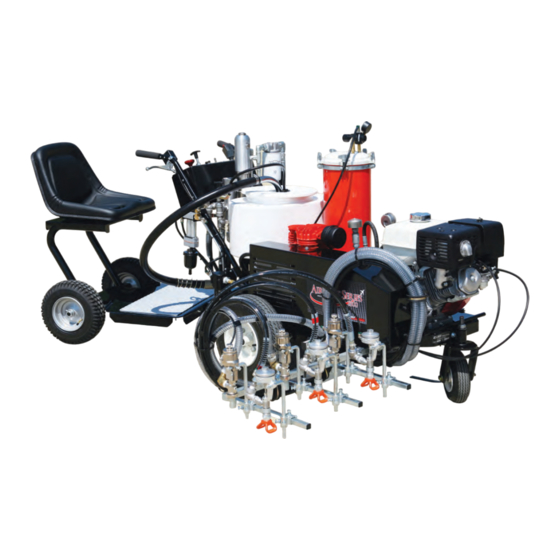
Summary of Contents for EZ-liner Pro Series 1300
-
Page 3: Table Of Contents
1300 paint striper - operating manual ez-liner pro series 1300 paint striper - operating manual TABLE OF CONTENTS Safety Summary ............................page-3 OPERATION SECTION General Product Information ....................page-6 introduction to controls & v alves ..................page-7 paint preparation ...........................page-13 pre-start up procedure ........................page-13... - Page 4 1300 paint striper - operating manual page-2 page-2...
-
Page 5: Safety Summary
1300 paint striper - operating manual Safety Summary NOTE: Since EZ-Liner Industries does not have control over how information in this manual is to be imple- mented, EZ-Liner shall not be liable for damages, including special, incidental or consequential damages out of or in connection with the implementation of the information contained in this manual. - Page 6 1300 paint striper - operating manual This airless equipment uses high pressure. Leaks from components or ruptured hoses can inject fluid through the skin and into the body. Injection of paint or other fluids such as hydraulic oil into the body can result in injury and could result in amputation of the affected area.
- Page 7 1300 paint striper - operating manual PAINTING SAFETY Never flush the system under high pressure. Never spray solvent or other flushing material through the guns with the spray tips in place. An explosion or fire could result from static electricity build-up in the presence of flammable vapors.
-
Page 8: Operation Section
1300 paint striper - operating manual OPERATION SECTION General Product Information Before using this machine, check for possible damage that may have occurred to the machine during shipment. If there is damage, contact the factory before making any repairs. -
Page 9: Introduction To Controls & V Alves
1300 paint striper - operating manual introduction to controls & v alves Engine Controls: The engine controls are located on the control console. They include a keyed on/off switch, a choke control, and a throttle control. Main Power: A switch on the control panel turns on the power for the machine. - Page 10 1300 paint striper - operating manual Hydraulic System Pressure Adjusting Bolt: Located on the hydraulic pump. Turning the bolt clockwise increases the pressure in the hydraulic system. Turning the bolt counterclockwise decreases the pressure. Located on the pressure reducing valve. Turning the Hydraulic HP Pump Pressure Control Knob: knob clockwise increases the pressure to the hydraulically powered paint pump.
- Page 11 1300 paint striper - operating manual Striping Speed Control Valve: Located to the left of the paint pump. Turning the knob clockwise will decrease the striping speed. Turning it counterclockwise will increase the paint striping speed. Drive Engagement Lever: This is a flexible lever mounted underneath the left handle bar.
- Page 12 1300 paint striper - operating manual 12. ead Tank Regulator: Located on the bead tank. Turning the knob clockwise increases the pressure in the bead tank. Turning the knob counter clockwise decreases the pressure. Pressure Relief Valve: Located at the top of the bead tank.
- Page 13 1300 paint striper - operating manual Paint Supply Valve(s): Located near the high pressure paint filter. There is one valve for each paint line. When the lever is in line with the body of the valve, the valve is open. When the lever is perpendicular, at 90 degree, to the body of the valve, it is closed.
- Page 14 1300 paint striper - operating manual Solenoid Valves: Electrically controlled air valves that turn the paint and bead guns on and off. Valves are located near the paint guns. Parking Brake: This is a manual lever that engages a stop to a rear wheel to keep the machine from rolling when the machine is parked.
-
Page 15: Paint Preparation
1300 paint striper - operating manual paint preparation Make sure the paint is thoroughly stirred. Check the paint manufacturer’s recommendations to see if the paint needs to be thinned when used in an airless spray system. If you are using old or dirty or poor quality paint, strain the paint through a filter bag or screen that is between 50 and 70 mesh. -
Page 16: Start Up Procedure
1300 paint striper - operating manual start up procedure Turn the gas on at the engine with slide lever located on the left side of the engine. Pull the throttle half way out. Pull the choke all the way out. -
Page 17: Painting Procedure
1300 paint striper - operating manual painting procedure Before actually painting adjust the guns to the desired distance from the machine and the desired spacing between the guns. Raise or lower the guns to a reasonable height. Make sure fasteners are tightened. - Page 18 1300 paint striper - operating manual Start the machine moving forward by pulling up on the Drive Engagement Lever under the left handle grip. After the machine is moving, press the button on the right gun control box all the way in. Paint should begin to spray out of the gun(s).
-
Page 19: Spray Tip Selection Guide
1300 paint striper - operating manual spray tip selection guide The spray tips needed for the PRO SERIES 1300 are dependant on the application, the paint viscosity and the paint temperature. The following is a guide for selecting the right spray tip. - Page 20 1300 paint striper - operating manual On a 3-gun unit the switch for “Beads” on the control panel must be in the “On” position for the bead guns to activate with the paint guns. The bead flow can be adjusted to zero flow by adjusting the pressure in the bead tank to zero. On the 3-gun unit this can also be done by turning the switch for “Beads”...
-
Page 21: Pressure Relief Guidelines
1300 paint striper - operating manual pressure relief guidelines High pressure spray can cause serious injury. Please follow these pressure relief guidelines to reduce the risk of injury, whenever you check or service any part of the system or when you install, clean, or change spray tips and whenever you stop spraying. -
Page 22: Flushing Guidelines - When To Flush
1300 paint striper - operating manual Clean the paint off of the threads and apply grease to them. Replace the filter in the outer casing and turn the cap on. The cap must only be hand tight. -
Page 23: Flushing Procedure - How To Flush
1300 paint striper - operating manual flushing procedure - how to flush Relieve the pressure in the paint system. Refer to the Pressure Relief Guidelines. Never flush the system under high pressure. Remove the spray tips. Never spray solvent or other flushing material through the guns with the spray tips in place. -
Page 24: Shut Down & Clean Up Procedures
1300 paint striper - operating manual shut down & clean up procedures Reduce the pressure in the hydraulic system by turning the System Pressure Adjusting Bolt on the hydraulic pump counterclockwise (out). Open the bleeder line valve and shut off the hydraulic oil supply valve going to the hydraulic motor section of the paint pump. -
Page 25: Maintenance Section
1300 paint striper - operating manual MAINTENANCE SECTION general maintenance Set up a regular maintenance schedule and keep an up-to-date history of the maintenance and repairs per- formed. Regular maintenance improves the efficiency of your unit and prolongs its useful life. A chart is included for your convenience. - Page 26 1300 paint striper - operating manual Air Filter : Model F74G, P/N: F74G-6AN-AP3 See details in Service Section. Laman Dryer : See instructions in Service Section. page-24 page-24...
-
Page 27: Hydraulic System
1300 paint striper - operating manual Unloader Valve: See instructions in Service Section Use a pipe sealant when reassembling any malleable iron pipe fittings to insure a good seal. Damage will result to the air compressor if compressor is run on an incline of greater than 10° for an extended period of time. -
Page 28: Paint System
1300 paint striper - operating manual Three simple maintenance procedures that have the greatest effect on hydraulic system performance, efficiency, and life. a. Maintain a clean, sufficient quantity of hydraulic oil of the proper type and viscosity. -
Page 29: Bead System
1300 paint striper - operating manual Binks Model 570: See Service Section for maintenance and servicing instructions. Spray Gun: a. Periodically disassemble the gun to clean and inspect the parts. Clean thoroughly and replace parts as needed per manufacturer’s instructions. -
Page 30: Maintenance Record Chart
1300 paint striper - operating manual maintenance record chart ITEM DATE DATE DATE DATE ENGINE Engine Oil Service Air Cleaner Replace Spark Plug AIR SUPPLY SYSTEM Air Compressor Filter Air Compressor Oil Air Line Filter Air Dryer... - Page 31 1300 paint striper - operating manual page-29 page-29...
Need help?
Do you have a question about the Pro Series 1300 and is the answer not in the manual?
Questions and answers