Advertisement
Quick Links
Supported Model
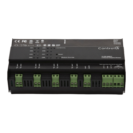
• C4-DIN-8DIM-E 8-Channel Dimmer
Introduction
The Control4® 8-Channel Dimmer controls up to eight (8) devices from one
module in the Control4 system. It installs in a panelized backbox using typical
wiring standards and communicates to the Control4 system using a CAT5 Ethernet
connection.
Dimming Mode Configuration
Each channel on the 8-Channel Dimmer can be set to several different dimming
modes:
• Switch Mode: Only allows the load to be set to 100% or off.
• Autodetect Mode: The dimmer will detect the load type and set forward or
reverse-phase dimming appropriately.
• Forward Phase Mode: Forces the channel into forward-phase (leading edge)
dimming.
• Reverse Phase Mode: Forces the channel into reverse-phase (trailing edge)
dimming.
The Autodetect, Forward Phase, and Reverse Phase modes should only be used
with dimmable loads.
In its factory default state, all channels on the 8-channel Dimmer are set to "Switch
Mode" to prevent inadvertent dimming of non-dimmable loads.
The mode can be configured for each channel using the buttons on the front of the
module:
1
Press the CH1 and CH8 buttons simultaneously.
2
All channel LEDs will change color indicating the current dimming mode:
• Solid Yellow – Switch Mode
• Solid Red – Autodetect Mode
• Solid Green – Forward Phase Mode
• Solid Blue – Reverse Phase Mode
Click each channel button to cycle through the four (4) dimming mode types.
3
4
Once each channel is set as desired, click the Module Override button to
initiate the autodetect sequence on any channels set to 'Autodetect Mode.'
The channel being autodetected will blink Red. When the autodetect test is
finished, the channel LED will go to one of the following states:
• Blinking Green – Autodetected forward phase
• Blinking Blue – Autodetected reverse phase
• Solid Red – Autodetect failed. Run the test again or set an alternate
mode.
5
Exit the configuration mode by pressing and holding the Module Override
button briefly. If any channels are still set to Autodetect (solid red), the
autodetect sequence will run for those channels.
8-Channel
Dimmer
Operation and
Configuration
Guide
™
The previous procedure should be repeated anytime that a module is rewired or a
load type changes.
NOTE:
Once the module has been identified into a project, it is no longer
possible to configure the dimming mode from the module. The dimmable/
non-dimmable load type and dimming mode settings in Composer must
be used to configure the dimming mode.
NOTE:
When first identifying a module into a project, if the dimming
mode of the light in Composer conflicts with the dimming mode of the
corresponding channel on the module, a warning will be presented forcing
the user to choose the appropriate dimming mode.
Composer Pro Configuration and Reports
Use Composer Pro to define the properties of each 8-Channel Dimmer, its location
in a panel, and the loads that are connected to it. Composer Pro can then be used
to generate Panel Reports, Module Reports, and Load Schedule Reports. These
reports are essential to ensuring that each 8-Channel Dimmer is properly installed
in the correct location and wired to the appropriate loads. Please refer to the
Composer Pro User Guide for detailed information.
Browser Configuration Tool
Basic properties for each load as well as the network configuration for the
8-Channel Dimmer can be set using a standard web browser. To open the
configuration page, simply start the browser and type in the IP address of the
dimmer. Alternatively, the Properties page for the module in Composer Pro has a
link to the browser configuration page.
The browser configuration tool can be used to set the following properties:
•
Network Settings
- DHCP Enable/Disable
- IP Address
- Subnet Mask
- IP Gateway
•
Control Settings for each Channel
- Dimmable/Non-Dimmable (locked out once identified into a project)
- Dimming Mode (locked out once identified into a project)
- Click Ramp Rate Up/Down
- Hold Ramp Rate Up/Down
- Minimum & Maximum Levels
- Preset Level
- Cold Start Level
- Module Override Level
Additionally, the browser configuration tool can be used to view the current
temperature of the dimmer as well as any channel short circuit faults.
LEDs
During normal operation, the indicator lights on the front of the 8-Channel Dimmer
communicate the status of the device.
Indicator
LED Color
Module Override
Blue
Black
Red
Channels
Blue
Black
Red
Status
Notes
Power on, normal
operation
Off
Thermal overload
See "Faults" section
below
Load on
Load off
Short Circuit Fault
See "Faults" section
below
Advertisement

Summary of Contents for Control 4 8-Channel
- Page 1 - Dimmable/Non-Dimmable (locked out once identified into a project) - Dimming Mode (locked out once identified into a project) In its factory default state, all channels on the 8-channel Dimmer are set to “Switch - Click Ramp Rate Up/Down Mode” to prevent inadvertent dimming of non-dimmable loads.
- Page 2 Reset button. Note that - The Aux In and Aux Out terminals on the 8-Channel Dimmer can be wired the same activity is possible by pressing and holding the designated button while...
-
Page 3: Troubleshooting
™ Troubleshooting Symptom Possible Solution Module does not Verify that the circuit breaker is on. power on Verify that Line-In 1 is connected to the power. Load does not turn on Verify that the load is wired to the proper channel terminal. - Page 4 Copyright ©2013 Control4. . All rights reserved. Control4, the Control4 logo, the Control4 iQ logo and the Control4 certified logo are registered trademarks or trademarks of Control4 Corporation in the United States and/or other countries. All other names and brands may be claimed as the property of their respective owners Pricing and specifications are subject to change without notice...