
Related Manuals for Aiwa CDC-R307


Summary of Contents for Aiwa CDC-R307
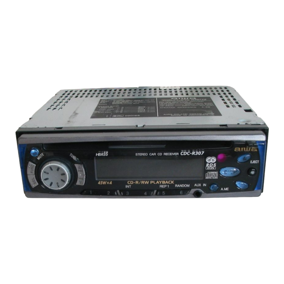
- Page 1 CDC-R307 CDC-RV407 SERVICE MANUAL STEREO CAR CD RECEIVER BASIC CD MECHANISM : CDC02AW1 • This Service Manual is the "Revision Publishing" and replaces "Simple Manual" (S/M Code No. 09-002-429-0T1). S/M Code No. 09-004-429-0R1...
-
Page 2: Specifications
SPECIFICATIONS RADIO SECTION AUDIO SECTION (FM) Max. Power Output 45 W x 4 channels Frequency Range 87.5 MHz –108 MHz (50 kHz steps) Usable Sensitivity 12.7 dBf AUX IN input 50 dB Quieting Sensitivity 17.2 dBf Input Sensitivity (load impedance) IF Rejection 80 dB AUX IN... - Page 3 PROTECTION OF EYES FROM LASER BEAM DURING SERVICING CAUTION This set employs laser. Therefore, be sure to follow carefully the instructions below when servicing. Use of controls or adjustments or performance of proce- dures other than those specified herin may result in WARNING!! hazardous radiation exposure.
- Page 4 CAUTION WHEN SERVICING 1. Disassembly Instruction 1) Remove the COVER TOP and COVER BOTTOM. 2) Remove the DFP. 3) Remove the four screws (indicated by arrows) from CD mechanism. (Fig. 1) Screw (a) × 2: VTT 2.6-6 Screw (b) × 2: VTT 2.6-3B Fig.
- Page 5 ELECTRICAL MAIN PARTS LIST REF. NO. PART NO. KANRI DESCRIPTION REF. NO. PART NO. KANRI DESCRIPTION C120 87-010-185-080 C-CAP,S 3900P-50 B C121 87-010-220-080 C-CAP,S 0.018-25BK 88-KT1-606-080 IC,PST994D C122 87-010-220-080 C-CAP,S 0.018-25BK 8Z-KT1-622-010 C-IC,LC75374E C123 87-012-358-080 C-CAP,S 0.47-10 FZ 87-A21-562-010 IC,LA4743B C124 87-012-358-080 C-CAP,S 0.47-10 FZ...
- Page 6 REF. NO. PART NO. KANRI DESCRIPTION REF. NO. PART NO. KANRI DESCRIPTION C453 87-012-358-080 C-CAP,S 0.47-10 FZ LCD951 8A-KC3-610-010 LCD,AKC-3/4(2 COLOR)<307> C454 87-010-197-080 CAP,CHIP 0.01 DM LCD951 8A-KC3-611-010 LCD,AKC-3/4(NO COLOR)<407> C501 87-012-358-080 C-CAP,S 0.47-10 FZ LED951 87-017-827-070 C-LED,SEC1201C RED C502 87-012-358-080 C-CAP,S 0.47-10 FZ LED952...
- Page 7 REF. NO. PART NO. KANRI DESCRIPTION REF. NO. PART NO. KANRI DESCRIPTION C857 87-010-880-080 C-CAP,E 47-6.3 MF L832 87-A50-536-080 C-COIL,10UH K LQH3C24 C861 87-016-669-080 C-CAP,S 0.1-25 K B L833 87-A50-536-080 C-COIL,10UH K LQH3C24 C862 87-016-669-080 C-CAP,S 0.1-25 K B L861 87-A50-536-080 C-COIL,10UH K LQH3C24 C863...
- Page 8 WIRING - 1 (MAIN) – 8 –...
- Page 9 SCHEMATIC DIAGRAM - 1 (MAIN) – 9 –...
- Page 10 WIRING - 2 (FRONT / JACK AUX / LED) 307 ONLY 307 ONLY - 10 -...
- Page 11 SCHEMATIC DIAGRAM - 2 (FRONT / JACK AUX / LED) – 11 –...
- Page 12 WIRING – 3 (CD / SENSOR) <1 / 2> – 12 –...
- Page 13 WIRING – 3 (CD) <2 / 2> – 13 –...
- Page 14 SCHEMATIC DIAGRAM - 3 (CD / SENSOR) – 14 –...
- Page 15 LCD DISPLAY < CDC-R307> LCD, AKC-3 / 4 (2 COLOR) – 15 –...
- Page 16 LCD DISPLAY < CDC – RV407> LCD, AKC-3 / 4 (NO COLOR) – 16 –...
- Page 17 IC DESCRIPTION IC, µPD178018AGC–554–3B9 Pin No. Pin Name Description FM/AM S-M Input RDS AF IN signal and FM/AM S meter signal. LEVEL IND Input level indicator signal. A-VOL CONT Detect mic input and operate auto volume. (Not used) CD CONNECT Connectivity check to CD changer.
- Page 18 Pin No. Pin Name Description CDS RESET CDS : Output reset signal. CDS SLEEP CDS : Output sleep signal. CDS STOP CDS : Input stop signal. CDS IN CDS : Input disc inserted status detection. TEST Test point. 46 ~ 47 Not connected.
- Page 19 IC, LC75374E Pin No. Pin Name Description RVR IN 4dB volume control input. Must be driven at a low impedance. R COM – 1dB volume control common pin. For the connection of capacitors that compensate for bass and treble in the tone control circuits. 3 ~ 5 RT1 ~ RT3 –...
- Page 20 Pin No. Pin Name Description TP(R) TUN(R) Signal input pins. CD(R) AUX(R) RSELO Input selector output pin. IC, LC75854W Pin No. Pin Name Description LCD segment output. LCD segment ouptut. (Not used) 3 ~ 37 S3 ~ S37 LCD segment output. 38 ~ 39 S38 ~ S39 LCD segment output.
- Page 21 IC, CXD2587Q Pin No. Pin Name Description SQSO Sub-Q 80-bit and PCM peak/level data output. CD TEXT data output. SQCK Clock input for reading SQSO. XRST System reset. Reset at "L". SYSM Muting input. Muted at "H". DATA Serial data input from CPU. XLAT Latch input from CPU.
- Page 22 Pin No. Pin Name Description Sled error signal input. Tracking error signal input. Neutral servo analog input. RFDC RF signal input. ADIO For test. (Not used) AVSS0 – Ground of analog circuits. IGEN Constant current input for OP amp. AVDD0 –...
- Page 23 IC, CXA2581N Pin No. Pin Name Description APC amp output. APC amp input. EQ-IN RFAC-system VCA/EQ block input. AC-SUM RFAC-system RF SUM output. – Ground. A-signal input. B-signal input. C-signal input. D-signal input. E-signal input. F-signal input. MODE switching signal input. DVCC Digital power supply.
- Page 24 IC, µPD78012FGC–656–AB8 Pin No. Pin Name Description TE-BAL – Not used. LO-REV Loading motor reverse drive output. LO-FWD Loading motor forward drive output. LIMT-SW Inner edge limit switch. RE-SW CD/CD-RW switching output. Outputs "H" when power is turned on. SV-CONT (When power is supplied, this pin outputs "H"...
- Page 25 Pin No. Pin No. Pin Name Pin Name Description Description DATA-DSP DSP serial data output. CD-MUTE Muting output. CD-RST CD reset output. AVDD – Power supply. AVREF – A/D converter reference voltage input. SQ-IN Sub-Q/PCM peak/level data input. – Not connected. SQCK Outputs clock for reading SQSO.
- Page 26 IC BLOCK DIAGRAM IC,LA4743B IC,LC75854W IC,BA6417F IC,LC75374E IC,BA6392FP REGISTER – 26 –...
- Page 27 IC,NJM4558MD IC,SAA6579T IC,TC4053BF IC,CXD2587Q – 27 –...
- Page 28 CD TEST MODE 1. How to activate CD test mode 3. CD test mode functions 1) Remove the resistor R907 (100kΩ) from the MAIN C.B, and add Mode Operation Key LCD Display Operation Contents R999C 22kΩ or chip resistor to the MAIN C.B. (Fig. 1) 2) Connect +12V to ACC/BACK UP and –...
- Page 29 MECHANICAL EXPLODED VIEW 1 / 1 P.C.B CDC02AW1 LCD 951 P.C.B P.C.B PANEL, HT-SINK H2-AC P.C.B SH,PWB – 29 –...
- Page 30 MECHANICAL PARTS LIST 1 / 1 REF. NO. PART NO. KANRI DESCRIPTION REF. NO. PART NO. KANRI DESCRIPTION 1 8A-KC7-005-010 KNOB,RTRY -AC 33 8Z-KC2-011-210 CABI,BASE -C2 2 8A-KC7-020-010 RING,RTRY -AC 34 8A-KCF-220-010 COVER, DUST DFP -AC 3 8A-KC7-220-010 SPR-C,ROTARY -AC 35 8Z-KC2-204-210 LEVER,DFP LOCK -C2 4 8A-KC4-001-010...
- Page 31 CD MECHANISIM EXPLODED VIEW 1 / 1 TABLE,DISC PICK BASE ASSY SENSOR, P.C.B MOTOR SPINDLE RF-400CA CORD 3P LEAD MOTOR A LEAD MOTOR B LEAD 2P CDC02AW1(12cm ONLY) (FileName:EXP.EPS) 2000/2/25 – 31 –...
- Page 32 CD MECHANISM PARTS LIST 1 / 1 REF. NO. PART NO. KANRI DESCRIPTION REF. NO. PART NO. KANRI DESCRIPTION 1 S1-100-510-130 COVER TOP 36 S1-100-520-170 LEVER,R 2 S1-100-510-090 LEVER RELEASE 37 S1-100-520-140 GEAR H CAM 3 S1-100-510-180 ARM START SET 38 S1-100-540-080 SP SUB DAMPER 4 S1-100-520-220...
- Page 33 2–11, IKENOHATA 1–CHOME, TAITO-KU, TOKYO 110, JAPAN TEL:03 (3827) 3111 9630472 0251431 Printed in Singapore...