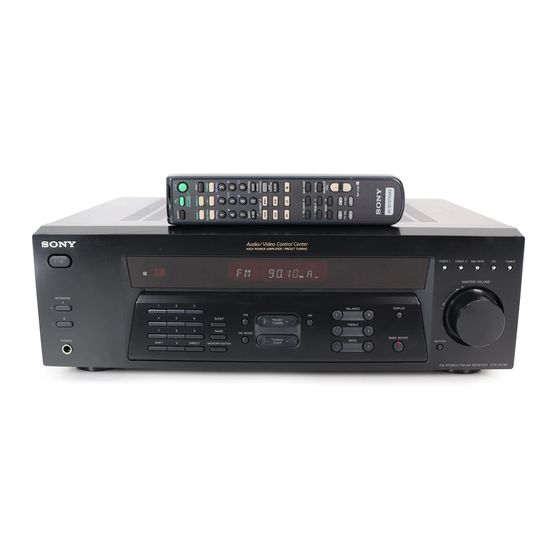
Sony STR-DE185 Service Manual
Fm stereo/fm-am receiver
Hide thumbs
Also See for STR-DE185:
- Operating instructions manual (34 pages) ,
- Product information (2 pages) ,
- Dimensions (1 page)
Table of Contents
Advertisement
SERVICE MANUAL
Ver 1.0 2002. 02
AUDIO POWER SPECIFICATIONS
POWER OUTPUT AND TOTAL
HARMONIC DISTORTION:
With 8 ohm loads, both channels driven, from
40 – 20,000 Hz; rated 100 watts per channel
minimum RMS power, with no more than
0.09 % total harmonic distortion from 250
milliwatts to rated output (Models of area code
US only).
Amplifier section
POWER OUTPUT
Models of area code US
Rated Power Output at Stereo Mode
(8 ohms 40 Hz – 20 kHz, THD 0.09 %)
100 W + 100 W
Models of area code AEP, UK
Rated Power Output at Stereo Mode
8 ohms 1 kHz, THD 0.7 %)
(
100 W + 100 W
1) Measured under the following conditions:
Area code
Power requirements
AEP, UK
230 V AC, 50 Hz
Frequency response
CD, MD/TAPE,
20 Hz – 50 kHz
VIDEO 1, VIDEO 2
+0/–0.5 dB (with bass
boost bypassed)
Inputs (Analog)
CD, MD/TAPE,
Sensitivity: 250 mV
VIDEO 1, VIDEO 2
Impedance: 50 kilohms
2)
S/N
: 85 dB
(A, 250 mV
2) INPUT SHORT.
3) Weighted network, input level.
Sony Corporation
9-873-586-01
2002B0400-1
Home Audio Company
© 2002.02
Published by Sony Engineering Corporation
SPECIFICATIONS
1)
3)
)
STR-DE185
Outputs
MD/TAPE, VIDEO 1
Voltage: 250 mV
Impedance: 10 kilohms
Bass Boost:
+8 dB at 70 Hz
Tone:
±10 dB at 100 Hz and
10 kHz
FM tuner section
Tuning range
87.5 – 108.0 MHz
Antenna terminals
75 ohms, unbalanced
Intermediate frequency
10.7 MHz
Sensitivity
Mono:
18.3 dBf, 2.2 µV/75 ohms
Stereo:
38.3 dBf, 22.5 µV/75 ohms
Usable sensitivity
11.2 dBf, 1 µV/75 ohms
S/N
Mono:
76 dB
Stereo:
70 dB
Harmonic distortion at 1 kHz
Mono:
0.5%
Stereo:
0.8%
Separation
35 dB at 1 kHz
Frequency response
30 Hz – 15 kHz,
+0.5/–2 dB
Selectivity
60 dB at 400 kHz
FM STEREO/FM-AM RECEIVER
US Model
AEP Model
UK Model
– Continued on next page –
1
Advertisement
Table of Contents

Related Manuals for Sony STR-DE185


Summary of Contents for Sony STR-DE185
-
Page 1: Service Manual
Sensitivity: 250 mV VIDEO 1, VIDEO 2 Impedance: 50 kilohms : 85 dB (A, 250 mV 2) INPUT SHORT. 3) Weighted network, input level. FM STEREO/FM-AM RECEIVER Sony Corporation 9-873-586-01 2002B0400-1 Home Audio Company © 2002.02 Published by Sony Engineering Corporation... - Page 2 COMPONENTS IDENTIFIED BY MARK 0 OR DOTTED LINE WITH MARK 0 ON THE SCHEMATIC DIAGRAMS AND IN THE PARTS LIST ARE CRITICAL TO SAFE OPERATION. REPLACE THESE COMPONENTS WITH SONY PARTS WHOSE PART NUMBERS APPEAR AS SHOWN IN THIS MANUAL OR IN SUPPLEMENTS PUBLISHED BY SONY.
-
Page 3: Table Of Contents
STR-DE185 SAFETY CHECK-OUT TABLE OF CONTENTS After correcting the original service problem, perform the following 1. GENERAL safety check before releasing the set to the customer: Main unit ................. 4 Check the antenna terminals, metal trim, “metallized” knobs, screws, Remote button description ............5 and all other exposed metal parts for AC leakage. -
Page 4: General
STR-DE185 SECTION 1 GENERAL This section is extracted from instruction manual. List of Button Locations and Reference Pages Illustration number How to use this page Use this page to find the location of buttons that are NAME 5 (18) mentioned in the text. -
Page 5: Remote Button Description
STR-DE185 Remote button description You can use the remote RM-U185 to operate The tables below show the settings of each the components in your system. button. Remote Operations Function Button SLEEP SLEEP Receiver Activates the sleep SYSTEM function and the duration... -
Page 6: Disassembly
STR-DE185 SECTION 2 DISASSEMBLY Note : This set can be disassemble according to the following sequence. 2-1. CASE (Page 6) 2-2. FRONT PANEL SECTION 2-3. BACK PANEL 2-4. MAIN BOARD (Page 7) (Page 7) (Page 8) Note : Follow the disassembly procedure in the numerical order given. -
Page 7: Front Panel Section
STR-DE185 2-2. FRONT PANEL SECTION 4 two screws (BVTP3 x 8) 2 CN5 3 CNP801 6 front panel section 1 CN4 5 four screws (BVTP3 x 8) 2-3. BACK PANEL 9 back panel (DE1) 8 screw (BVTP3 x 8) 2 CNP901... -
Page 8: Main Board
STR-DE185 2-4. MAIN BOARD 2 CNP905 1 CNP904 3 two screws 4 two screws (BVTP3 x 8) (BVTP3 x 8) 5 screw (BVTP3 x 8) 6 screw (BVTP3 x 8) 8 MAIN board... -
Page 9: Test Mode
STR-DE185 SECTION 3 TEST MODE Fluorescent Indicator Tube Test Mode All fluorescent segments are tested. When this test is activated, all segments turn on at the same time, then each segment turns on one after another. Procedure: 1. While pressing the five function buttons of [VIDEO 1], [VIDEO 2], [MD/TAPE], [CD] and [TUNER] simultaneously, press the button to turn the power ON. -
Page 10: Diagrams
STR-DE185 SECTION 4 DIAGRAMS 4-1. IC PIN DESCRIPTION • IC201 µPD78044FGF-200-3B9 (SYSTEM CONTROLLER, FL DRIVER) Pin No. Pin Name Pin Description 1 to 7 DIG7 to 1 Digit drive signal output to the fluorescent indicator tube (FL201). — Power supply pin (+5 V) Serial clock signal output to FM/AM tuner pack. -
Page 11: Circuit Boards Location
STR-DE185 4-2. CIRCUIT BOARDS LOCATION Pin No. Pin Name Pin Description RY R1 COIL Power relay (12V) drive signal output RY POWER AC power relay (9V) drive signal output RY A Speakers A relay (12V) drive signal output OUTLET board... -
Page 12: Block Diagram - Main Section
STR-DE185 4-3. BLOCK DIAGRAM — MAIN SECTION — TM301 FM/AM TUNER UNIT VIDEO,MD/TAPE +10V SOUND CONTROL AUDIO AMP SELECT IC401 IC403 IC404 J801 (2/2) TUNER REC L L CH FM 75Ω COAXIAL MD/TAPE R CH R CH R-CH VOL L... -
Page 13: Block Diagram - Power Section
STR-DE185 4-4. BLOCK DIAGRAM — POWER SECTION — R-CH PRE DRIVER J803 IC601 PHONES DRIVE +VOUT IN 1 POWER AMP ST-L DRIVE Q701-704 -VOUT ST-R R-CH OVERLOAD BIAS Q705,706 R-CH PROTECT TM801 SWITCH Q784-786 SPEAKERS IMPEDANCE 13 14 15 RELAY DRIVER R-CH USE 8-16Ω... -
Page 14: Printed Wiring Board - Main Section
STR-DE185 4-5. PRINTED WIRING BOARD — MAIN SECTION — • Refer to page 11 for Circuit Boards Location and page 15 for Common Note on Printed Wiring Boards. J801 J802 TM801 IC903 T902 RR752 B901 CC753 D982 CC703 RR702 CC704... -
Page 15: Printed Wiring Boards - H/P, Outlet Section
STR-DE185 4-6. PRINTED WIRING BOARDS — H/P, OUTLET SECTION — • Refer to page 11 for Circuit Boards Location. THIS NOTE IS COMMON FOR PRINTED WIRING BOARDS AND SCHEMATIC DIAGRAMS. (In addition to this, the necessary note is printed in each block.) for schematic diagram: •... -
Page 16: Schematic Diagram - Main Section (1/2)
STR-DE185 4-7. SCHEMATIC DIAGRAM — MAIN SECTION (1/2) — • Refer to page 15 for Common Note on Schematic Diagram and page 20 for IC Block Diagrams. R481 R482 R926 J801 CC451 R451 R452 C452 C484 IC B/D CC401 R401... -
Page 17: Schematic Diagram - Main Section (2/2)
STR-DE185 4-8. SCHEMATIC DIAGRAM — MAIN SECTION (2/2) — • Refer to page 15 for Common Note on Schematic Diagram and page 20 for IC Block Diagrams. CNP802 CNP801 RY781 J803 R792 C702 R707 Q703 R793 C704 R784 Q705 R781... -
Page 18: Schematic Diagram - Display Section
STR-DE185 4-9. SCHEMATIC DIAGRAM — DISPLAY SECTION — • Refer to page 15 for Common Note on Schematic Diagram. R227 C217 R228 C218 IC202 C215 R303 C214 R229 R230 FL201 C225 R231 R293 R232 R242 C204 R233 R294 R295 R234... -
Page 19: Printed Wiring Board - Display Section
STR-DE185 4-10. PRINTED WIRING BOARD — DISPLAY SECTION — • Refer to page 11 for Circuit Boards Location and page 15 for Common Note on Printed Wiring Boards. (Page 14) (Page 20) (Page 14) • Semiconductor Location Ref. No. Location... -
Page 20: Printed Wiring Board - Power Sw Section
STR-DE185 4-11. PRINTED WIRING BOARD — POWER SW SECTION — • IC Block Diagrams • Refer to page 11 for Circuit Boards Location and page 15 for Common Note on Printed Wiring Boards. IC401 BD3861FS IC402 TC9299P 16 VDD VIDEO1 L... -
Page 21: Exploded Views
STR-DE185 SECTION 5 EXPLODED VIEWS NOTE: • The mechanical parts with no reference • Color Indication of Appearance Parts The components identified by mark 0 or dotted line with mark number in the exploded views are not supplied. Example : 0 are critical for safety. -
Page 22: Front Panel Section
STR-DE185 5-2. FRONT PANEL SECTION supplied with RV201 Ref. No. Part No. Description Remark Ref. No. Part No. Description Remark 4-232-113-01 KNOB (VOL) 4-951-620-01 SCREW (2.6X8), +BVTP 4-921-941-01 CUSHION 1-765-332-11 WIRE (FLAT TYPE) (15 CORE) X-4954-453-1 PANEL ASSY, FRONT (US) -
Page 23: Chassis Section
STR-DE185 5-3. CHASSIS SECTION F902 F901 Q754 Q753 Q704 Q703 not supplied T901 TM301 not supplied not supplied The components identified by mark 0 or dotted line with mark. 0 are critical for safety. Replace only with part number specified. -
Page 24: Electrical Parts List
STR-DE185 SECTION 6 DISPLAY ELECTRICAL PARTS LIST NOTE: • Due to standardization, replacements in • Items marked “*” are not stocked since The components identified by mark 0 or dotted line with mark. the parts list may be different from the they are seldom required for routine service. - Page 25 STR-DE185 DISPLAY Ref. No. Part No. Description Remark Ref. No. Part No. Description Remark R245 1-249-429-11 CARBON 1/4W R298 1-249-425-11 CARBON 4.7K 1/4W R246 1-249-429-11 CARBON 1/4W R299 1-247-807-31 CARBON 1/4W R247 1-249-429-11 CARBON 1/4W R300 1-247-807-31 CARBON 1/4W R248...
- Page 26 STR-DE185 DISPLAY MAIN Ref. No. Part No. Description Remark Ref. No. Part No. Description Remark S233 1-771-410-21 SWITCH, TACTILE (CD) C462 1-126-964-11 ELECT 10uF S234 1-771-410-21 SWITCH, TACTILE (MD/TAPE) C463 1-126-794-11 ELECT 4.7uF S235 1-771-410-21 SWITCH, TACTILE (VIDEO 2) C464 1-136-167-00 FILM 0.15uF...
- Page 27 STR-DE185 MAIN Ref. No. Part No. Description Remark Ref. No. Part No. Description Remark C912 1-135-851-21 MYLAR 0.22uF 100V < CONNECTOR > C913 1-135-851-21 MYLAR 0.22uF 100V C914 1-165-946-11 DOUBLE LAYERS 6800uF 1-569-060-11 SOCKET, CONNECTOR 11P (US) C915 1-165-946-11 DOUBLE LAYERS 6800uF...
- Page 28 STR-DE185 MAIN Ref. No. Part No. Description Remark Ref. No. Part No. Description Remark IC904 8-759-701-75 IC NJM7805FA (AEP,UK) R418 1-249-433-11 CARBON 1/4W R421 1-249-437-11 CARBON 1/4W < JACK > R422 1-249-433-11 CARBON 1/4W R423 1-249-433-11 CARBON 1/4W J801 1-774-411-11 JACK, PIN 6P (CD,MD/TAPE)
- Page 29 STR-DE185 MAIN OUTLET Ref. No. Part No. Description Remark Ref. No. Part No. Description Remark R704 1-249-408-11 CARBON 1/4W R914 1-249-425-11 CARBON 4.7K 1/4W 0 R915 R705 1-249-408-11 CARBON 1/4W 1-240-877-11 FUSIBLE 0.15 1/2W F R706 1-233-352-41 COMPONENT, ENCAPSULATED 0.22X2...
- Page 30 STR-DE185 POWER SW Ref. No. Part No. Description Remark Ref. No. Part No. Description Remark 1-683-817-11 POWER SW BOARD ACCESSORIES **************** ************ < DIODE > 1-477-133-11 REMOTE COMMANDER (RM-U185) 1-501-374-11 ANTENNA, LOOP (AM) D205 8-719-046-39 LED SEL5821A-TP15 (SPEAKERS A) 1-501-594-11 ANTENNA (FM) (AEP,UK)
- Page 31 STR-DE185 MEMO...
- Page 32 STR-DE185 REVISION HISTORY Clicking the version allows you to jump to the revised page. Also, clicking the version at the upper right on the revised page allows you to jump to the next revised page. Ver. Date Description of Revision...