
Related Manuals for Force 10 Galley

Summary of Contents for Force 10 Galley
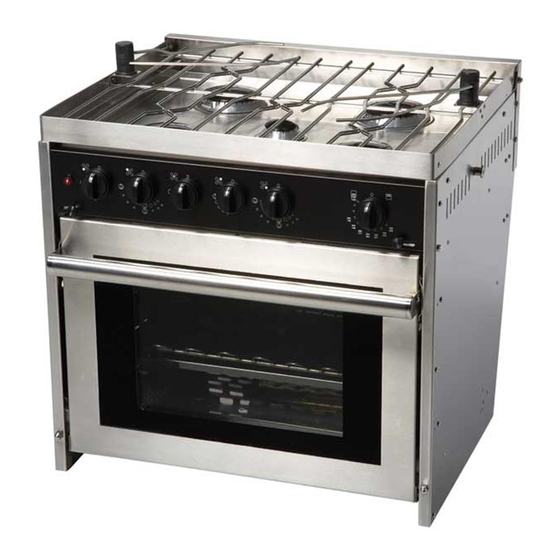
- Page 1 Professional Series Galley Range OWNER’S MANUAL Read all instructions and warnings before operating. Force 10 Manufacturing Corporation Unit A – 19169 21 Surrey, BC V3S 3M3 Tel: 604.536.0379 Fax: 604.535.1210 Website: www.force10.com...
-
Page 2: Safety And Precautions
Any recommendation or advice given by Force 10 Marine Company or any of its employees is solely an accommodation to the customer, and should not be relied upon by the customer without an independent verification of its applicability to the customer’s particular situation. -
Page 3: Gas Pressure
GAS PRESSURE Your Force 10 Galley Ranges (unless otherwise specified) is designed to operate from low pressure Propane gas. Pressure Orifice Size (mm) / By Pass (mm) mbar Auxiliary Rapid Broiler Thermostatic Burner Burners Oven Burner Propane 0.44 0.45/ 0.30 0.78/ 0.47... -
Page 4: Gimbal Installation
Minimum Clearances to Overhead Cabinets 30" (762mm) minimum clearance between the top of the cooking surface and the bottom of an unprotected wood or metal cabinet; 24” (610mm) minimum when bottom of wood or metal cabinet is protected by a flame retardant heat shield. -
Page 5: Built-In Installation
Built-in Installation Cutout Dimensions: Width: 25.1” (635 mm) Depth: 21.75” (553 mm) Height: 24.5.” (623 mm) The opening between the cabinets should be 25” (635mm) wide, 21.75” (553mm) deep and 24.5” (623mm) high. This height leaves clearance for changing the battery. Attach the trim kit and front spacer to the right and left stove sides as shown in the diagram below using the enclosed screws. -
Page 6: Operation
OPERATION Features Your Force 10 Professional Series range has a number of features to make your unit easier to use. Pot Holders - There are (2) sets of Pot holders included with your unit. These Pot holders are designed to hold pots in place during movement. To install the pot holder, screw the unit (clockwise) into the black base on either side of the top grill. - Page 7 (MUST ENGAGE SPOOL) CLASP OPEN Oven door - Your Force 10 Range is equipped with a slide away space saving door. To open the door, lift up on the handle and pull towards you. The door will fold underneath the oven.
- Page 8 To light the top burners: • Push in the control knob that corresponds to the burner you are lighting, and turn counter-clockwise 90º. • Continue pushing the control knob in, while pushing the ignition button located on the left side of the control panel. (There will be a spark at all the burners) •...
- Page 9 Oven: • To light the oven push in the oven control knob and turn counter-clockwise to the desired temperature setting. Pushing in the control knob will engage the integrated spark ignition system. • Once the burner is lit, continue to hold the control knob in for (20) seconds to allow the thermocouple to heat up and energize the solenoid inside the valve.
-
Page 10: Cleaning And Maintenance
CLEANING & MAINTENANCE Cleaning Stainless Steel Do not use abrasive pads; they will scratch the surface The basic rule of thumb is to use the mildest cleaning procedure that will do an effective job. Always rinse thoroughly with clear water and dry completely. Frequent cleaning will prolong the service life of stainless steel equipment and help maintain the finish. - Page 11 Removal of the top burner orifices: • Twist the burner cap counter-clockwise and lift up. • Remove the flame spreader. • Using an 7mm socket unscrew and remove the brass orifice. • Re-assemble the burner before use insuring the burner cap is attached. Orifice Removal of the oven orifice: •...
- Page 12 Changing the battery The electronic ignition system is powered from a AA 1.5 Volt Battery. The Battery holder is located at the back of the stove, under the door. To change the battery, unscrew the black cap. Remember to respect the polarity. Replacing a Thermocouple Tools Required: Phillips Head screwdriver...
-
Page 13: Troubleshooting Guide
TROUBLE SHOOTING GUIDE PROBLEM CAUSE Solution______________ Burner will not stay lit Thermocouple is not in the See Low Flame flame Thermocouple has failed Replace thermocouple Solenoid in the valve has Replace solenoid failed Supply tank is empty Re-fill tank Burner will not light (No gas) Shut-off valve is closed Open valve... -
Page 14: Assembly Diagrams
Assembly Diagrams Page 13 of 15... - Page 15 Gas and Electrical Circuits Page 14 of 15...
-
Page 16: Specifications
The buyer shall be responsible for shipping and insurance charges, if any, on the products returned for repair under the terms of this warranty. Force 10 Manufacturing will pay shipping of products returned to the buyer.