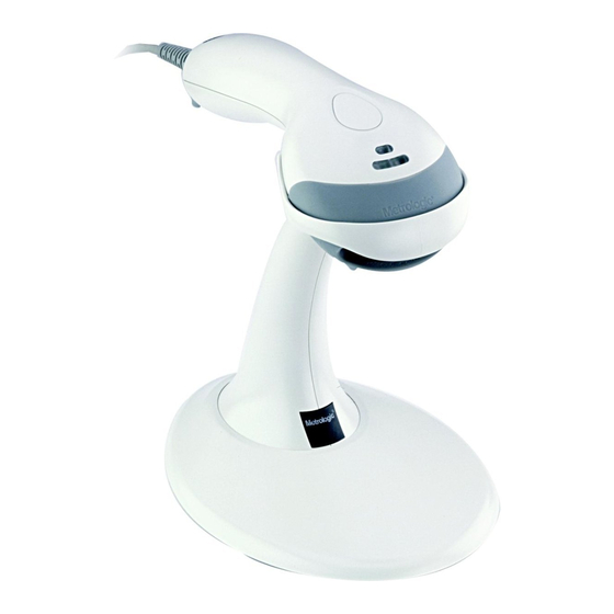
Honeywell MS9500 Voyager Series User Manual
Single-line hand held laser scanner
Hide thumbs
Also See for MS9500 Voyager Series:
- Stand installation manual (2 pages) ,
- User manual (49 pages)

Related Manuals for Honeywell MS9500 Voyager Series


Summary of Contents for Honeywell MS9500 Voyager Series
- Page 1 ® MS9500 Voyager Series Single-Line Hand Held Laser Scanner Installation and User's Guide...
- Page 2 Disclaimer Honeywell International Inc. (“HII”) reserves the right to make changes in specifications and other information contained in this document without prior notice, and the reader should in all cases consult HII to determine whether any such changes have been made. The information in this publication does not represent a commitment on the part of HII.
-
Page 3: Table Of Contents
ABLE OF ONTENTS Introduction Product Overview ..................... 1 Scanner and Accessories................. 2 Scanner Components..................4 The PowerLink Cable Disconnecting....................5 Connecting ....................5 Labels....................... 6 Maintenance..................... 6 Installing the Scanner to the Host System RS232, Laser Emulation, and Light Pen Emulation.......... 7 RS485 ...................... - Page 4 ABLE OF ONTENTS IR Activation Range.................... 25 Applications and Protocols ................. 26 Troubleshooting Guide ..................27 Design Specifications Operational..................... 30 Mechanical ..................... 31 Electrical......................31 Environmental ....................31 Scanner and Cable Terminations Scanner Pinout Connections ................32 Cable Connector Configurations ..............34 Limited Warranty ....................
-
Page 5: Product Overview
(single-line) laser scanners offers the user an aggressive solution for scanning all standard 1D bar codes including GS1 DataBar™ (RSS) bar codes. The MS9500 series is equipped with both in-stand and out-of-stand operation enabling hand-held or fixed projection scanning. -
Page 6: Scanner And Accessories
MS9520 Voyager Bar Code Scanner MS9540 VoyagerCG Bar Code Scanner with CodeGate 00-02544 MetroSelect Single-Line Configuration Guide* MS9500 Voyager Series Single-Line Hand Held Laser 00-02410 Scanner Installation and User’s Guide* Available for download at - www.honeywellaidc.com PTIONAL CCESSORIES Part # Description AC to DC Power Transformer - Regulated 5.2VDC @ 1A output. - Page 7 NTRODUCTION Scanner and Accessories PTIONAL CCESSORIES Part # Description USB Full Speed Cable Locking Plus-Power™ Type A, 53-53213x-N-3 Black, Coiled Cord with Long Strain Relief USB Full Speed Cable Locking Plus-Power™ Type A, Black, Coiled Cord with Long Strain Relief, Extended Length 53-53214x-N-3 Not for use with Low Speed USB scanners.
-
Page 8: Scanner Components
NTRODUCTION Scanner Components Item Description ♦ Green LED See Visual Indicators on page 18 ♦ Red LED See Visual Indicators on page 18 ♦♦ Yellow LED See Visual Indicators on page 18 ♦♦ Button See How to use CodeGate on page 12 Red Window Laser Aperture Speaker... -
Page 9: Disconnecting
NTRODUCTION Disconnecting the PowerLink Cable Before removing the cable from the scanner, Honeywell recommends that the power on the host system is off and the power supply has been disconnected from the PowerLink cable. Figure 2. Locate the small ‘pin-hole’ on the top of the unit near the bottom of the scanner. -
Page 10: Labels
NTRODUCTION Labels Every scanner has labels and molded text located on the underside of the unit. The labels and text contain important information such as the unit’s date of manufacture, serial number, CE and caution information. Figure 5 provides examples of the labels and the molded text. Figure 5 . -
Page 11: Installing The Scanner To The Host System
NSTALLING THE CANNER TO THE YSTEM RS232, Laser Emulation, and Light Pen Emulation Turn off the host system. Connect the 10-pin RJ45 male connector into the jack on the scanner. There will be an audible click when the connector lock engages. -
Page 12: Rs485
NSTALLING THE CANNER TO THE YSTEM RS485 Turn off the host system. Plug the male 10-pin RJ45 end of the MVC cable into the 10-pin socket on the scanner. There will be an audible click when the connection is made. Connect the other end of the MVC cable to the host device. -
Page 13: Keyboard Wedge
NSTALLING THE CANNER TO THE YSTEM Keyboard Wedge Turn off the host system. Connect the 10-pin RJ45 male connector into the jack on the scanner. There will be an audible click when the connection is made. If the scanner is receiving power from the host system, skip to step #5. -
Page 14: Stand-Alone Keyboard
NSTALLING THE CANNER TO THE YSTEM Stand-Alone Keyboard Turn off the host system. Connect the 10-pin RJ45 male connector into the jack on the scanner. There will be an audible click when the connection is made. If the scanner is receiving power from the host system, skip to step #5. -
Page 15: Integrated Usb Full Speed
NSTALLING THE CANNER TO THE YSTEM Integrated USB: Full Speed (-40) Low Speed (-38) Turn off the host system. Connect the 10-pin RJ45 male connector of the USB cable into the jack on the scanner. There will be an audible click when the connection is made. -
Page 16: The Ms9540 Voyagercg ® Series
® MS9540 V OYAGER ERIES How to Use CodeGate and the Manual Activation Mode ® ANUAL CTIVATION This feature is not a default setting. Refer to the MetroSelect Configuration Guide for instructions on enabling the Manual Activation Mode. Figure 11. Figure 12. -
Page 17: Stand Kits
Hard Mount Accessory Kit #46-46351 (Figure 14) This kit, used in conjunction with the stand kit (#46-46128), can be used to hard mount (bolt) the MS9500 to the countertop. Figure 14. Kit Contains: a. Screw, #8 Round Head ......Qty. 4 b. -
Page 18: Assembly
TAND Assembly There are two options for assembling the stand. The first option is a self- supporting stand that can be moved freely about on the countertop. The second option is used if the stand will be bolted or hard-mounted to the countertop. Stand Option 1: Self-Supported Stand Kit #46-46128 Apron Step 1... - Page 19 TAND Assembly Stand Option 2: Hard-Mount Kits #46-46128 and #46-46351 Anchor from Step 3 Kit #46-46128 Screw the stand anchor onto the base Base Assembly from assembly until it sits flush. Kit #46-46351 or MS951 Stand Base Figure 21. Step 4 Remove the logo plate on the stand by gently using an exacto knife to release the plate hook.
- Page 20 TAND Assembly Wall Mount, Option 1: For Kit #46-46508 Step 1 Drill two #39 pilot holes 3.00″ apart. Step 2 Attach the Wall Mount Hanger to the wall with the two #8 wood screws provided. Figure 26. Wall Mount, Option 2: Kit #46-46508 Step 1 Attach the Wall Mount Base to the...
-
Page 21: Indicators
NDICATORS Audible When the Voyager is in operation, it provides audible feedback. These sounds indicate the status of the scanner. Eight settings are available for the tone of the beep (normal, six alternate tones and no tone). To change the beeper tone, refer to the MetroSelect Single-Line Configuration Guide or MetroSet2’s help files. -
Page 22: Visual
NDICATORS Visual Figure 29. LED Configuration The MS9540 has three LED indicators located on the head of the scanner. The MS9520 has two LED indicators located on the head of the scanner. When the scanner is in operation, the flashing, or stationary activity of the LEDs indicates the status of the scanner and the current scan. -
Page 23: Failure Modes
NDICATORS Failure Modes Razzberry Tone – On Start-Up This indicates the scanner has experienced a flipper/motor failure. Return the unit for repair to an authorized service center. Continuous Razzberry Tone with all LEDs Off If, upon power, the scanner emits a continuous razzberry tone, then the scanner has an experienced an electronic failure. -
Page 24: Configuration Modes
ONFIGURATION ODES The MS9500 Voyager has three modes of configuration. Bar Codes The MS7120 can be configured by scanning the bar codes located in the MetroSelect® Single-Line Configuration Guide. This manual is available for download at www.honeywellaidc.com. MetroSet®2 ®... - Page 25 ONFIGURATION ODES During configuration, the motor and laser turn off. YOU CANNOT SCAN A BAR CODE WHILE IN SERIAL CONFIGURATION MODE. There is a 20 second window between commands. If a 20 second timeout occurs, the scanner will send a [nak] and you must start over. To enter serial configuration mode, send the following command [stx]999999[etx].
- Page 26 ONFIGURATION ODES EXAMPLE #3: The following example shows the events that occur when an invalid bar code is sent. This sample will load the factory default settings and then set the baud rate to 19200. SCANNER HOST ASCII RESPONSE FEATURE COMMAND REPRESENTATION [stx]999999[etx]...
-
Page 27: Upgrading The Firmware
PGRADING THE IRMWARE The Voyager series is part of Honeywell’s line of scanners with flash upgradeable firmware. The upgrade process requires a new firmware file supplied to the customer by a customer service representative and MetroSet2 software personal computer running Windows 95 or greater with an available RS232 serial or USB port is required to complete the upgrade. -
Page 28: Depth Of Field
EPTH OF IELD INIMUM LEMENT IDTH mils Figure 30. Depth of Field... -
Page 29: Ir Activation Range
IR detects movement in the activation area (see figure below), the laser will automatically turn on, preparing the scanner for bar code recognition, decoding, and transmission. The default laser/scan mode for the MS9500 series is normal scan. Figure 31. Short and Long IR Activation Area... -
Page 30: Applications And Protocols
TTL RS232 Transmit/Receive The MS9520/9540 Keyboard Wedge Series (-47) is designed for keyboard emulation only. Many RS232 configurable functions available in other Honeywell scanners are also available as keyboard wedge functions. The following are the most important selectable options specific to keyboard... -
Page 31: Troubleshooting Guide
ROUBLESHOOTING UIDE The following guide is for reference purposes only. Contact a customer service representative to preserve the limited warranty terms on page 36. Symptoms Possible Causes Solution All Interfaces Check the transformer, the outlet No power is being and power strip. Make sure the supplied to the unit. - Page 32 ROUBLESHOOTING UIDE Symptoms Possible Causes Solution The bar code being Verify that the bar code being The unit powers scanned does not scanned falls into the configured up, but does not satisfy the configured criteria. scan and/or criteria for character beep.
- Page 33 ROUBLESHOOTING UIDE Symptoms Possible Causes Solution The following four items are relevant for a Keyboard Wedge interface only. Make sure that the proper PC type The unit scans AT, PS2 or XT is selected. Verify The unit’s configuration but the data is the correct country code and data is not correct.
-
Page 34: Design Specifications
ESIGN PECIFICATIONS MS9500 Series Specifications PERATIONAL Light Source Visible Laser Diode 650 nm Laser Power: Less than 1 mW (peak) 0 mm - 203 mm (0" - 8") for Depth of Scan Field: 0.330 mm (13 mil) bar code at default settings... -
Page 35: Mechanical
ESIGN PECIFICATIONS MS9500 Series Specifications ECHANICAL Length: 198 mm (7.8") Width: Handle - 45 mm (1.8"), Head - 78 mm (3.1") Depth: 40 mm (1.6") Weight: 149 g (5.25 oz) LECTRICAL Input Voltage: 5VDC ± 0.25V Operating = 0.825 W typical Power: Standby = 0.600 W typical... -
Page 36: Scanner And Cable Terminations
CANNER AND ABLE ERMINATIONS Scanner Pinout Connections The MS9520 and MS9540 MS95x0-41 scanner interfaces terminate to RS232 and Light Pen Emulation a 10-pin modular jack. Function The serial number label Ground indicates the interface enabled RS232 Transmit Output when the scanner is shipped RS232 Receive Input from the factory. - Page 37 CANNER AND ABLE ERMINATIONS Scanner Pinout Connections MS95x0-00 Laser Emulation Function Ground RS232 Transmit Output RS232 Receive Input Flip Sense/Start of Scan Output Proximity Detect/Trigger Emulation Output Scan/Laser Enable Input Reserved Data Out +5VDC Shield Ground MS95x0-40 Full Speed USB & MS95x0-14 RS232 MS95x0-38 Low Speed USB Function...
-
Page 38: Cable Connector Configurations
CANNER AND ABLE ERMINATIONS Cable Connector Configuration (Host End) RS232 PowerLink Cable 53-53000x-3 Function Shield Ground TTL RS232 Transmit Output TTL RS232 Receive Input DTR Input/Light Pen Source Signal Ground Light Pen Data (DSR Out for -14 interfaces) CTS Input 9-Pin Female, D-Type RTS Output +5VDC... - Page 39 PC Clock No Connect Honeywell will supply an adapter cable with a 5-pin DIN male connector on one end and a 6-pin mini DIN female connector on the other. According to the termination required, connect the appropriate end of the adapter cable to the PowerLink cable, leaving the necessary termination exposed for connecting to the keyboard and the keyboard port on the PC.
-
Page 40: Limited Warranty
These warranties are non- transferable. The duration of the limited warranty for the MS9500 is five (5) year(s). The accessories have a 90 day limited warranty from the date of manufacture. -
Page 41: Regulatory Compliance Safety
EGULATORY OMPLIANCE Safety ITE Equipment IEC 60950-1, EN 60950-1 Laser Laser Class 1: IEC 60825-1:1993+A1+A2, EN 60825-1:1994+A1+A2 Caution Use of controls or adjustments or performance of procedures other than those specified herein may result in hazardous laser light exposure. Under no circumstances should the customer attempt to service the laser scanner. -
Page 42: Emc
EGULATORY OMPLIANCE Emissions FCC Part 15, ICES-003, CISPR 22, EN 55022 Immunity CISPR 24, EN 55024 Note: Immunity performance is not guaranteed for scanner cables greater than 3 meters in length when fully extended. Changes or modifications not expressly approved by the party responsible for compliance could void the user’s authority to operate the equipment. -
Page 43: Class B Devices
EGULATORY OMPLIANCE Standard Europeo Attenzione Questo e’ un prodotto di classe A. Se usato in vicinanza di residenze private potrebbe causare interferenze radio che potrebbero richiedere all’utilizzatore opportune misure. Attention Ce produit est de classe “A”. Dans un environnement domestique, ce produit peut être la cause d’interférences radio. -
Page 44: Patents
ATENTS This Honeywell product may be covered by, but is not limited to, one or more of the following U.S. Patents: US Patent No. 5,081,342; 5,260,553; 5,340,971; 5,340,973; 5,424,525; 5,468,951; 5,484,992; 5,525,789; 5,528,024; 5,591,953; 5,616,908; 5,627,359; 5,661,292; 5,777,315; 5,789,730; 5,789,731; 5,811,780; 5,825,012; 5,828,048; 5,883,375; 5,886,337;... -
Page 45: Index
NDEX AC ........see power green LED....see indicator accessories .......3, 4 adapter ..........3 IBM ....see interface: RS485 immunity........43 indicator cable......3–4, 30–32 adapter ........3 audible....... 24, 33 communication ... 1, 3–4, 6, 8–13, failure ........ 30–32 32, 35–39 visual ....... - Page 46 NDEX specifications ......33, 34 pin assignments ....see cable stand ......... 4, 16–19 power ......3, 8–13, 34 PowerLink....39, see cable termination ......35–39 protocols..... see interface troubleshooting ..... 30–32 Red LED......see indicator regulatory compliance ...41–44 UL ......... see caution repair ...........40 USB ......see interface RMA ..........40...
-
Page 47: Customer Support
UPPORT Technical Assistance If you need assistance installing or troubleshooting your device, please call your distributor or the nearest technical support office: North America/Canada Telephone: (800) 782-4263 E-mail: hsmnasupport@honeywell.com Latin America Telephone: (803) 835-8000 Telephone: (800) 782-4263 E-mail: hsmlasupport@honeywell.com Brazil... -
Page 48: Product Service And Repair
USTOMER UPPORT Product Service and Repair Honeywell International Inc. provides service for all its products through service centers throughout the world. To obtain warranty or non-warranty service, contact the appropriate location below to obtain a Return Material Authorization number (RMA #) before returning the product. - Page 52 Honeywell Scanning & Mobility 9680 Old Bailes Road Fort Mill, SC 29707 www.honeywellaidc.com 00-02410 Rev L December 2009...