Table of Contents
Advertisement
Advertisement
Table of Contents

Summary of Contents for FHP 641-224
- Page 1 I/O ZONE 560/583 USERS GUIDE 641-224 641-242 641-237...
-
Page 2: Table Of Contents
Table of Contents Hot Gas Re-Heat Valve On/Off:......... 15 THE ZONE CONTROLLER......4 Modulating Re-Heat Valve: .......... 16 Filter: ................16 SPECIFICATIONS ........5 Heating and Cooling – (1 and 2 Compressor Stages): 16 CONTROLLER COMPONENTS ....6 The heating will be enabled whenever:....... 17 The cooling will be enabled whenever: ...... - Page 3 Pump Control (optional)..........31 NOTES ................41 Pump Runtime Alarm:..........31 Load Water (Entering) Temperature: ......32 Load High Temp: ............32 Load Low Temp: ............32 Load Sensor Failure: ...........32 Source Water (Leaving) Temperature: ......32 Leaving High Temp: ...........32 Leaving Low Temp: ............32 Leaving Sensor Failure:..........32 BACview Termination Detail........35 RS-Sensor Termination Detail ........37 NOTES ........
-
Page 4: The Zone Controller
The Zone Controller The Zone control board also known as DDC The controller is programmed in the factory and shown in figure 1 is used in most with software versions that suit the different configure to order applications. applications FHP offers. User settings such It is BACnet®... -
Page 5: Specifications
Specifications Power: 24VAC ± 10%, 50-60Hz, 20VA power consumption (Single Class II 70VA or 100VA option available) Physical: Rugged plastic housing protects circuitry. Environmental Operating Range: 40° to 130°F (-17.8° to 54.4°C); 10 to 90% relative humidity, non-condensing Digital Outputs: Five digital outputs relay contacts rated at 1A resistive @ 24VAC;... -
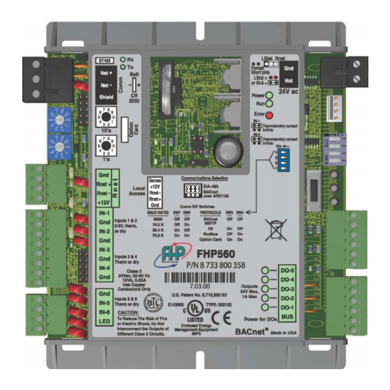
Page 6: Controller Components
Controller Components Controller Components LED Indicators LED Indicators The DDC controller is equipped with three The DDC controller is equipped with three bank sets of LED that help the user bank sets of LED that help the user diagnose problems and or identify normal diagnose problems and or identify normal operation. -
Page 7: Dip And Rotary Switches
Figure 4 – Digital Output LEDs The Third Bank of LEDs are located on the bottom right corner of the controller as shown on figure 4 (right) and their purpose is to show the status of individual Digital Outputs (DO) as they are energized DIP and Rotary Switches Figure 5 –... -
Page 8: Jumpers And Settings
PROTOCOLS ® BACnet MS/TP I M P O R T A N T : LonTalk® card Modbus must be installed. Option Card Jumpers set up will be cover under the jumper Typical DIP switch for LonTalk® (Option section. Card) is shown in figure 8. Figure 8 - LonTalk®... -
Page 9: Lonworks® Card Option
The LON card option is available for both controllers 641-224 and 641-242. The Lon card connects to the option card port as shown in figure 11. -
Page 10: Water To Air Operation
Water to Air Operation General Description The Heat Pump Factory mounted I/O Zone 560 or 583 DDC Controllers are factory configured with the Water to Air application program and factory installed in the unit to be job site configureable to run. The unit will operate in a 100% stand-alone control mode or connect to a Building Automation System (BAS) using open protocols BACnet®... -
Page 11: Inputs
Inputs RS Room temperature sensor (Rnet) RS Room temperature sensor Set point adjust (Rnet) RS Room temperature sensor Occupancy override (Rnet) Discharge air temperature sensor Leaving water temperature sensor Unit Protection module (UPM) Alarm codes (7 safety shutdown alarms) ... -
Page 12: Status
Status Cooling/Heating control status Cooling/Heating percentage (0-100%) Room temperature Discharge air temperature Leaving water temperature Changeover temperature Unit filter status (optional) Fan-Hours runtime counter (filter replacement indicator) Fan starts counter Comp 1 starts counter ... -
Page 13: Sequence Of Operation
Sequence of Operation Run Conditions: The unit will run according to a user definable time schedule, dry contact (physical digital input number 1), manual ON command from BACview control interface, timed local override from Zone temperature sensor or via third party front end start command (software point). When commanded to run the unit will operate in the following modes: Occupied Mode: The unit will maintain ... -
Page 14: Zone Temperature
Zone Temperature The occupant will be able to see the zone temperature on the sensor LCD display in addition the user will be able to see other parameters that have been configured in the controller such as alarm status, alarm codes, Inputs and outputs status among others. NOTE: These codes and values vary from version to version for additional information on what is available on the RS-Pro sensor please check its commissioning BACview manual in our web site www.fhp-mfg.com. -
Page 15: Freeze Protection
Freeze Protection: The unit shall shut down and generate an alarm upon receiving a freezestat status. Fan: Constant Volume In the occupied mode, the fan shall run continuously or cycle with the compressor(s) depending on fan mode settings. In the unoccupied mode, fan cycles as required for unoccupied heating and cooling setpoints while in night setback. -
Page 16: Modulating Re-Heat Valve
Modulating Re-Heat Valve: This valve is an analog device and has the capability to modulate the amount of hot gas that is allowed through the re-heat coil, thus allowing control of the discharge air temperature to a user defined setpoint. The operation is similar to the on/off control except once the space temperature is satisfied the controller will monitor the space humidity if the value is greater than the setpoint the controller will modulate the valve to meet a particular a desired discharge air temperature on zone... -
Page 17: The Heating Will Be Enabled Whenever
The heating will be enabled whenever: The fan output is on. AND the reversing valve is in heat mode (de-energized). The cooling will be enabled whenever: The fan output is on. AND the reversing valve is in cool mode (energized). ... -
Page 18: Discharge Air Temperature
The controller will only allow supplemental heating if the unit is configured to allow this operation, units equipped with hot gas re heat valves or damper control enable will not have supplemental electric heat functionality. Discharge Air Temperature: The controller will monitor the discharge air temperature to be located at discharge side of coil. If the supplemental heating is installed then sensor will be in the discharge side of heating coil. -
Page 19: Single Outside Air Temperature (Oat) Reset
Single Outside Air Temperature (OAT) Reset: OAT> OAT Reset °F (adj.): Controller will initiate cooling call to run compressors and modulate Re-heat Valve only when the outside air temperature is greater than 55°F (Factory Default) OAT< OAT Reset °F (adj.): Controller will initiate a call for heating. -
Page 20: Leaving Water Temperature
Controller will command the unit to run full mechanical cooling operation (on units with more than two compressors please check with factory), the valve will be set for cooling operation and both first and second compressors will be commanded on, the fan will run continuously or if the unit is equipped with a Variable Frequency Drive (VFD) it will command the drive to maintain its static pressure setpoint and the re-heat valve will be modulated to maintain a 65°F (Factory Default (adj.)) discharge air temperature setpoint . - Page 21 Figure 12 - Typical water to air applications – Water to Air Standard...
- Page 22 Figure 13 -Typical water to air applications – Water to Air with Hot Gas Re-Heat...
- Page 23 Figure 14 - Typical water to air applications – Water to Air with CO2 and OA Damper...
- Page 24 Figure 15 – Typical water to air application – Discharge Air Control with Modulating Reheat Valves...
- Page 26 Figure 16 - Typical water to air integration points list...
-
Page 27: Water To Water Operation
Water to Water Operation General Description The Heat Pump Factory mounted I/O Zone 560 or 583 DDC Controllers are factory configured with the Water to Water application program and factory installed in the unit to be job site configurable to run. The Unit will operate in a 100% stand-alone control mode or connect to a Building Automation System (BAS) using open protocols BACnet®... -
Page 28: Control & Status Parameters And Alarms
Control & Status Parameters and Alarms Status and Control BACview occupancy schedule System control: Schedule, Manual ON, BAS or DI Enable Load (entering) water temperature Leaving (source) water temperature Changeover temperature (optional) Cooling/Heating control status ... -
Page 29: Sequence Of Operation
Sequence of Operation Run Conditions: The unit will run according to a user definable time schedule, dry contact (physical digital input number 1), manual ON command from BACview control interface or via third party front end start command (BV software point). When commanded to run the unit will operate in the following modes: Occupied Mode: The unit will maintain ... -
Page 30: Digital Input Mode
Auto Cool: Chageover Temperature > Changeover Setpoint + Change over dead Band Auto Heat: Chageover Temperature < Changeover Setpoint - Change over dead Band When using the changeover feature the system will require an air temperature sensor (10KΩ @ 77°F (25°C) Thermistor) typically located in the controlled zone. -
Page 31: Lead - Lag Compressor Operation
Lead - Lag Compressor operation NOTE: This feature is only available on two stage systems. The unit will alternate the compressors by using Lead Lag control algorithm; the rotation method is user definable and can be set during the commissioning process as follows: ... -
Page 32: Load Water (Entering) Temperature
Load Water (Entering) Temperature: The controller will monitor the entering load water temperature which is located at entering side of coil. Alarms will be provided as follows: Load High Temp: If the water temperature at the entering load side is greater than the cooling setpoint plus a user definable amount (adj.), the factory default for this amount is 10°F. - Page 33 Figure 17 - Typical water to water applications – Water to Water Standard...
- Page 35 Figure 18 - Typical water to water integration points list...
-
Page 36: Bacview Termination Detail
BACview Termination Detail... -
Page 37: Rs-Sensor Termination Detail
RS-Sensor Termination Detail The RS Sensor is remotely mounted and installed (up to 500ft) in the zone it is recommended to use shielded cable (20AWG conductors) if installing RS-sensor only. If BACview is installed remotely using the same cable is recommended to use shielded cable (18AWG conductors). - Page 38 The RS-Pro Sensor interface The RS-Pro sensor factory part number 641-230 is a combination keypad/display unit that attaches to a control module to let you view and change temperature and set points values and the controller’s components status, the following features only apply to the software version covered on this manual.
- Page 39 IMPORTANT: By Pressing the Info button on the sensor the user can see the following typical data: PRESS 1 – Displays occupancy override time (in minutes) INFO PRESS 2 – Displays actual heating setpoint (in degrees F) PRESS 3 – Displays actual cooling setpoint (in degrees F) PRESS 4 –...
- Page 40 NOTES...
- Page 41 NOTES...
- Page 42 601 N.W. 65 Court, Ft. Lauderdale, FL 33309 Phone: 954-776-5471 Fax: 954-776-5529 www.fhp-mfg.com 970-443 REV. 6-11...