Advertisement
Quick Links
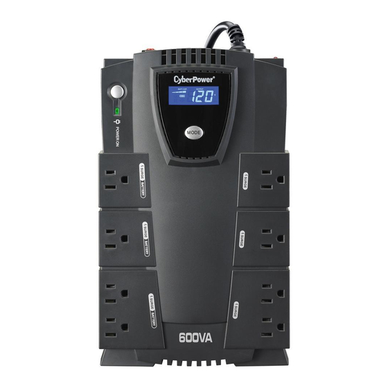
CP600/785/825LCD
User's Manual
IMPORTANT SAFETY WARNINGS
(SAVE THESE INSTRUCTIONS)
This manual contains important safety instructions. Please read and follow all instructions carefully during installation and
operation of the unit. Read this manual thoroughly before attempting to unpack, install, or operate your UPS.
CAUTION! To prevent the risk of fire or electric shock, install in a temperature and humidity controlled indoor area free of
conductive contaminants. (Please see specifications for acceptable temperature and humidity range).
CAUTION! To reduce the risk of electric shock, do not remove the cover except to service the battery. No user serviceable parts
are inside except for battery.
CAUTION! Some components can be energized by the battery even when the AC input power is disconnected.
CAUTION! UPS must be connected to an AC power outlet which has a fuse or is connected to a circuit breaker. Do not plug into
an outlet that is not grounded.
CAUTION! To avoid electrical shock, turn off the unit and unplug it from the AC power source before servicing the battery or
installing a computer component.
DO NOT USE FOR MEDICAL OR LIFE SUPPORT EQUIPMENT! CyberPower Systems does not sell products for life support or
medical applications. DO NOT use in any circumstance that would affect operation or safety of any life support equipment or with
any medical applications or patient care.
DO NOT USE WITH OR NEAR AQUARIUMS! To reduce the risk of fire or electric shock, do not use with or near an aquarium.
Condensation from the aquarium can cause the unit to short out.
DO NOT USE WITH LASER PRINTERS! The power demands of these devices will overload and possibly damage the unit.
INSTALLING YOUR UPS SYSTEM
UNPACKING
Inspect the UPS upon receipt. The box should contain the following:
R
(1) UPS unit; (1) User's manual; (1) PowerPanel
Personal Edition software CD; (1) USB device cable; (1) Telephone cable; (1)
Warranty registration card
HOW TO DETERMINE THE POWER REQUIREMENTS OF YOUR EQUIPMENT
1. Make sure that the total Volt-Amp (VA) requirements of your computer, monitor and peripheral equipments does not exceed
rated VA as spec.
2. Ensure that the equipment plugged into the four battery power-supplied outlets does not exceed the UPS unit's rated capacity
. If rated unit capacities are exceeded, an overload condition may occur and cause the UPS unit to shut down or the circuit
breaker to trip.
3. If the power requirements of your equipment are listed in units other than Volt-Amps (VA), convert Watts (W) or Amps (A) into
VA by doing the calculations below. Note: The below equation only calculates the maximum amount of VA that the equipment
can use, not what is typically used by the equipment at any one time. Users should expect actual usage values to be
approximately 60% of the calculated values.
Watts (W) x 1.67 =
VA
or
Add the totals up for all pieces of equipment and multiply this total by 0.6 to calculate actual power requirements.
There are many factors that can affect the amount of power that your computer system will require. The total load that you will
be placing on the battery-powered outlets should not exceed 80% of the unit's capacity.
HARDWARE INSTALLATION GUIDE
1. Your new UPS may be used immediately upon receipt. However, recharging
the battery for at least 16 hours is recommended to ensure that the battery's
maximum charge capacity is achieved. A loss of charge may occur during
shipping and storage. To recharge the battery, simply leave the unit plugged
into an AC outlet. The unit will charge in both the ON as well as the OFF
position. If you wish to use the software, use the enclosed USB devices cable
to connect the UPS to your computer. If you are not going to use the
software, you do not need to connect the cable.
2. With the UPS unit turned off and unplugged, connect your computer, monitor and any externally powered data storage device
(Zip drive, Jazz drive, Tape drive, etc ) into the battery power supplied outlets. Plug your peripheral equipment (printer,
scanner, speakers) into the full-time surge protection outlets. DO NOT plug a laser printer, paper shredder, copier, space
heater, vacuum or other large electrical device into the UPS. The power demands of these devices will overload and
possibly damage the unit.
3. To protect a fax, phone or modem, connect a telephone cable from the wall jack outlet to the "in" jack of the UPS. Connect a
telephone cable from the "out" jack with the CPU icon to the modem port on your computer. The "out" jack with the telephone
icon can be used to protect a telephone or fax machine.
4. Plug the UPS into a 2 pole, 3 wire grounding receptacle (wall outlet). Make sure the wall branch outlet is protected by a fuse
or circuit breaker and does not service equipment with large electrical demands (e.g. refrigerator, copier, etc ). The warranty
prohibits the use of extension cords, outlet strips, and surge strips.
5. Press the power switch to turn the unit on. The power on indicator light will illuminate and the unit will "beep" once.
6. If an overload is detected, an audible alarm will sound and the unit will emit one long beep. To correct this, turn the UPS off
and unplug at least one piece of equipment from the battery power supplied outlets. Wait 10 seconds. Make sure the circuit
breaker is depressed and then turn the UPS on.
7. Your UPS is equipped with an auto-charge feature. When the UPS is plugged into an AC outlet, the battery will automatically
recharge.
8. To maintain optimal battery charge, leave the UPS plugged into an AC outlet at all times.
9. To store your UPS for an extended period, cover it and store with the battery fully charged. While in storage recharge the
battery every three months to insure battery life.
BASIC OPERATION
DESCRIPTION
5
2
2
6
6
11
9
12
7
8
1
1
8
4
3
4
Power On Indicator
This LED is illuminated when the utility condition is normal and the UPS outlets are providing power, free of surges and
spikes.
Electrical Wiring Fault Indicator
5
This LED indicator will illuminate to warn the user that a wiring problem exists, such as bad ground, missing ground or
reversed wiring. If this is illuminated, user is advised to disconnect all electrical equipment from the outlet and have an
electrician check to ensure the outlet is properly wired. The unit will not provide surge protection without being plugged into
a grounded and properly wired wall outlet.
Communication Protection Ports
6
Communication protection ports will protect any standard modem, fax or telephone line.
P/N: K01-0000016-00
Amps (A) x 120 =
VA
1
Battery and Surge Protected Outlets
The unit has four battery powered/surge protected
outlets for connected equipments and ensures
temporary uninterrupted operation of your
equipment during a power failure.
2
Full-Time Surge Protection Outlets
The unit has four always on surge suppression
outlets.
3
Power Switch
10
Can be used as a master on/off switch for
equipment connected to the battery power supplied
outlets
7
Circuit Breaker
Located on the side of the UPS, the circuit breaker serves to provide overload and fault protection.
8
Software Communication Port
The port allows connection and communication from the USB on the computer to the UPS unit. The UPS communicates its
status to the PowerPanel
R
Personal Edition software. This interface is also compatible with the Power Management
R
R
provided by Windows
2000 and Windows
XP.
R
Note: To install PowerPanel
Personal Edition Software the computer will need Microsoft
installed.
9
Outlets Designed for AC Transformer
The unit has four Transformer Spaced Outlets blocks to be plugged into the UPS without blocking adjacent outlets.
Vertical Use Stand
10
The unit can be placed on it end in a vertical orientation.
Note: We recommend you place the unit next to the wall when standing the unit vertically.
11
LCD Module Display
High resoluation and intelligent LCD panel shows all the UPS information with icons and messages. For more information
please check the "Definitions for Illuminated LCD Indicators" section.
12
LCD panel Toggle/Selected Switch
The switch can be used to select the LCD panel contents including Input Voltage, Output Voltage and Estimated Run Time.
The toggle frequency is set to one time per second. Holding the switch for more than two seconds while running on battery
will silence the buzzer.
DEFINITIONS FOR ILLUMINATED LCD INDICATORS
INPUT voltage meter: This meter measures the AC voltage that the UPS system
is receiving from the utility wall outlet. The UPS is designed, through the use of
automatic voltage regulation, to continuously supply connected equipment with
stable, 110/120 output voltage. In the event of a complete power loss, severe
brownout, or over-voltage, the UPS relies on its internal battery to supply
consistent 110/120 output voltage. The INPUT voltage meter can be used as a
diagnostic tool to identify poor-quality input power.
OUTPUT voltage meter: This meter measures, in real time, the AC voltage that
the UPS system is providing to the computer, such as normal line mode, and
The LCD display indicates a variety of
battery backup mode.
UPS operational conditions. All
Note: The OUTPUT voltage meter shows the status of the battery backup outlets.
descriptions apply when the UPS is
plugged into an AC outlet and turned
ESTIMATE RUN TIME: This displays the run time estimate of the UPS with the
on or when the UPS is on battery.
current battery capacity and load.
NORMAL icon: This icon appears when the UPS is working under normal conditions.
BATTERY icon: During a severe brownout or blackout, this icon appears and an alarm sounds (two short beeps followed by a
pause) to indicate the UPS is operating from its internal batteries. During a prolonged brownout or blackout, the alarm will sound
continuously (and the BATT.CAPACITY meter shows one 20% capacity segment shaded) to indicate the UPS's batteries are
nearly out of power. You should save files and turm off your equipment immediately.
OVER LOAD icon: This icon appears and an alarm sounds to indicate the battery-supplied outlets are overloaded. To clear the
overload, unplug some of your equipment from the battery-supplied outlets until the icon turns off and the alarm stops.
BATT. CAPACITY meter: This meter displays the approximate charge level (in 20% increments) of the UPS?s internal battery.
During a blackout or severe brownout, the UPS switches to battery power, the BATTERY icon appears, and the charge level
decreases.
LOAD CAPACITY meter: This meter displays the approximate output load level (in 20% increments) of the UPS?s battery
outlets.
REPLACING THE BATTERY
CAUTION! Read and follow the IMPORTANT SAFETY INSTRUCTIONS before servicing the battery. Service the battery under
the supervision of personnel knowledgeable of batteries and their precautions.
CAUTION! Use only the specified type of battery. See your dealer for replacement batteries.
CAUTION! The battery may present a risk of electrical shock. Do not dispose of battery in a fire as it may explode. Follow all
local ordinances regarding proper disposal of batteries. Almost any retailer that sells lead-acid batteries collects used batteries
for recycling, as required by most state laws.
CAUTION! Do not open or mutilate the batteries. Released electrolyte is harmful to skin and eyes and may be toxic.
CAUTION! A battery can present a high risk of short circuit current and electrical shock. Take the following precautions before
replacing the battery:
1. Remove all watches, rings or other metal objects.
2. Only use tools with insulated handles.
3. Do not lay tools or metal parts on top of battery or any terminals.
4. Wear rubber gloves and boots.
5. Determine if the battery is inadvertently grounded. If grounded, remove the source of ground. CONTACT WITH GROUNDED
BATTERY CAN RESULT IN ELECTRICAL SHOCK!
TO REPLACE THE BATTERY
1. Turn off and unplug all connected equipment.
2. Turn the UPS off and unplug it from the AC power source.
3. Turn the UPS upside down.
4. Remove the 1 retaining screw.
5. Slide the battery compartment cover completely off of the unit.
6. Remove the battery from the compartment.
7. Disconnect the battery wires from the battery.
8. Install the replacement battery by connecting the red wire and black wire to the positive (+) and negative (-) terminal of the
battery.
9. Put the battery back into the compartment.
10. Slide back the battery compartment cover and tighten the retaining screw.
11. Recharge the unit for 4 - 8 hours to fully charge the battery.
REMINDER: Batteries are considered HAZARDOUS WASTE and must be disposed of properly. Almost any retailer that sells
lead-acid batteries collects used batteries for recycling, as required by most state laws.
TROUBLE SHOOTING
Problem
Possible Cause
Full-time surge protection outlets
stop providing power to
Circuit breaker has tripped due to an
equipment. Circuit breaker
overload.
button is projecting from the side
of the unit.
Battery is not fully charged
The UPS does not perform
expected runtime.
Battery is slightly worn out.
The on/off switch is designed to
prevent damage by rapidly turning it
off and on.
The unit is not connected to an AC
outlet.
The UPS will not turn on.
The battery is worn out.
Mechanical problem.
R
Internet Explore 5.0 or higher
Solution
Turn the UPS off and unplug at least one piece of equipment.
Wait 10 seconds, reset the circuit breaker by depressing the
button, and then turn the UPS on.
Recharge the battery by leaving the UPS plugged in.
Contact CyberPower Systems about replacement batteries at
tech@cyberpowersystems.com
Turn the UPS off. Wait 10 seconds and then turn the UPS on.
The unit must be connected to a 110/120v 60Hz outlet.
Contact CyberPower Systems about replacement batteries at
tech@cyberpowersystems.com
Contact CyberPower Systems at
tech@cyberpowersystems.com
Advertisement

Related Manuals for CyberPower CP600


Summary of Contents for CyberPower CP600
-
Page 1: Important Safety Warnings
CAUTION! To avoid electrical shock, turn off the unit and unplug it from the AC power source before servicing the battery or installing a computer component. DO NOT USE FOR MEDICAL OR LIFE SUPPORT EQUIPMENT! CyberPower Systems does not sell products for life support or DEFINITIONS FOR ILLUMINATED LCD INDICATORS medical applications. -
Page 2: Technical Specifications
(952) 403-9500 or Toll-free: (877) 297-6937. CyberPower is the warrantor under this Limited Warranty. You may also contact 4. Pack and ship the Product to CyberPower as instructed in your RMA. Show the RMA code on the shipping label or include it CyberPower on the Internet at www.cyberpowersystems.com...