Table of Contents
Advertisement
Quick Links
About this Manual
We've added this manual to the Agilent website in an effort to help you support
your product. This manual is the best copy we could find; it may be incomplete
or contain dated information. If we find a more recent copy in the future, we will
add it to the Agilent website.
Support for Your Product
Agilent no longer sells this product. Our service centers may be able
to perform calibration and repair if necessary, but no other support from
Agilent is available. You will find any other available product information on the
Agilent Test & Measurement website, www.tm.agilent.com.
HP References in this Manual
This manual may contain references to HP or Hewlett-Packard. Please note that
Hewlett-Packard's former test and measurement, semiconductor products and
chemical analysis businesses are now part of Agilent Technologies. We have
made no changes to this manual copy. In other documentation, to reduce
potential confusion, the only change to product numbers and names has been in
the company name prefix: where a product number/name was HP XXXX the
current name/number is now Agilent XXXX. For example, model number
HP8648A is now model number Agilent 8648A.
Advertisement
Table of Contents

Related Manuals for HP 4145A


Summary of Contents for HP 4145A
- Page 1 Agilent Test & Measurement website, www.tm.agilent.com. HP References in this Manual This manual may contain references to HP or Hewlett-Packard. Please note that Hewlett-Packard's former test and measurement, semiconductor products and chemical analysis businesses are now part of Agilent Technologies. We have made no changes to this manual copy.
- Page 2 OPERATION SERVICE MANUAL MODEL 4145A SEMICONDUCTOR PARAMETER ANALYZER SERIAL NUMBERS This manual applies to instruments with serial numbers prefixed 2149J- and above. COPYRIGHT: YOKOGAWA-HEWLETT-PACKARD, LTD., 1982 9-1, TAKAKURA-CHO, HACHIOJI-SHI, TOKYO, JAPAN Manual Part No. 04145-90000 Printed: AUG. 1984 Microfiche Part...
- Page 3 Table of Contents Model 4145A TABLE OF CONTENTS Title Page Section Title Section Page INFORMATION GENERAL Introduction ... . . 3-37. Auto-Calibration ..3-27 l-l. 3-28 3-40. Display Pages ...
- Page 4 Model 4145A Table of Contents TABLE OF CONTENTS L’ Section Title Page Section Title Page 5-34. Disc Check ....5-23 3-127. Protection againt Hazard- Flexible-disc Drive...
- Page 5 ....5-14 3-97 HP-GL Commands ....5-5. DIAGNOSTICS Mode ..
- Page 6 List of Illustrations LIST OF ILLUSTRATIONS Number Title Page Number Title Page 3-38. HP-IB Control Switch ..3-86 l-l. Model 4145A and Accessories ..Remote Program Codes and 3-39. l-2. Serial Number Plate .... 3-88 Parameter Setting ..3-40. Data Output Format ....
- Page 7 5-14. D-A Converter Gain Adjustment 8-l. Four Major Sections of the 4145A Setup ..... . . 5-16 8-2. Overall Block Diagram ..
- Page 8 ..8-107 HP-IB and MSU 8-49. Control Board Assembly Component Locations 8-112 8-50. A9 HP-IB and MSU Control Board Assembly Schematic Diagram . 8-113 8-51. Block Diagram Key Control . . 8-115 8-52.
-
Page 9: Introduction
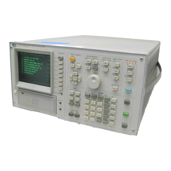
4145A 04145-61622 required) -p&+-/y,, 04145-61623 04145-61,630 Figure l-l. Model 4145A and Accessories. i P-L ==-? lm?-&oC3... - Page 10 All PLOT and PRINT When used as a current and 5mV, respectively. operations done automatically, without source/voltage monitor (I mode), each SMU can controller. Also, the 4145A’s display is equipped be programmed to output currents from *lpA with X-Y-Z outputs to allow connection...
- Page 11 Also, the 4145A is remotely controllable via the 1-15. This operation service manual HP-IB and the 4145A’s display can be used as an contains information, cautions, warnings independent display via the HP-IB. which must be followed by the user to ensure...
- Page 12 Options are modifications to the standard instrument that implement user’s special requirements for minor functional changes. 4145A has four options : Option 907 : Front Handle Kit. Furnishes Carrying handles both ends of front-panel. Option 908 : Rack Frange Kit. Furnishes...
-
Page 13: L-L. Specifications
SECTION I Model 4145A Table l-l. Specifications (Sheet 1 of 8) For 16058A specifications, refer to * Specifications listed below are for the 4145A only. the 16058A Operation Note. GENERAL INFORMATION : Measures DC current through voltage-biased devices and the... - Page 14 SECTION I Model 4145A Table l-l. Wecifications (Sheet 2 of 8) Resolution Accuracy Max. Voltage Current Range 2ov (>SOmA) 4ov (>2OmA) +lOOmA lOOnA 0.3%+(0.1+0.2*Vo/100)% 1 OpA +lOmA +1000l~A II-IA +1 OOuA 1 OOnA 1oov (62OmA) *lOuA 1 OnA 0.5%+(0.1+0.2*Vo/100)% 1%+(0.1+0.2*Vo/100)%+5pA Voltage, 4*1/2 digits (1mV max.);...
- Page 15 Model 4145A SECTION I of 8) Table l-l. Snecifimtions (Sheet Voltage Sources (Vs) : Two Vs channels. Each Vs can be programmed to function as a variable or constant DC voltage source. Output ranges, resolution, accuracy specifications are given in the table below.
- Page 16 SECTION I Model 4145A of 8) Table l-l. Snwifications (Sheet SPECIFICATIONS COMMON TO ALL CHANNELS Voltage : 1OOV (SMU, guard terminal, Vs, and Vm) Maximum Withstand Maximum Voltage Between Common and GND : Less than +42V. Source Modes (SMUs Only) :...
- Page 17 Model 4145A SECTION Table l-l. Specifications (Sheet 5 of 8) DISPLAY FUNCTIONS Alu- Display CRT. Electrostatic focus deflection, post accelerated. minized P-3 1 phosphor. Screen Size : 16cm (6.25in) diagonal. Screen Resolution : 2048 x 2048 points. Display Characters Symbols...
- Page 18 SECTION I Model 4145A TRhle l-l. Srwcifimtions (Sheet G of ARITHMETIC ANALYSIS FUNCTIONS expressions entered executed Arithmetic Functions Arithmetic directly from the front panel. Results are displayed on the CRT. Arithmetic Operators +, -, /, /- , EXP (Napierian constant),...
- Page 19 Model 4145A SECTION I T:,hlp _ Snp~ifimtinm fS.hppt 7 nf A - - . . - -p----‘- . , * - .., . . - - - . , , AUTO SCALE GRAPHIC plots can be automatically...
- Page 20 External Plotter/Printer Output Measurement data data appear- ing on the CRT may be output via the HP-IB to an HP plotter/printer operated in the LISTEN ONLY Mode. Output is initiated using the PLOT or PRINT key. HP-GL Control The CRT...
-
Page 21: Reference Data
Model 4145A SECTION I Tnhlo Rnfnrnnna nata (Chant 1 r\f ‘2) REFERENCE DATA It is not guaranteed specifications, (The following information is reference data only. does it include Test Fixture specifications.) + ranging time + integration time)/1 point Measurement Time... - Page 22 SECTION I Model 4145A Table l-2. Reference Data (Sheet 2 of 3) STIMULUS/MEASUREMENT UNIT (SMU) Offset Current when operated as a Voltmeter : 6pA + 2pA x Vo/lOO Offset Voltage when operated as a Current Meter : 1OmV + 0.4Q x IO...
- Page 23 16058-60003 Personality Board 16058-60004 PTFE Blank Board 16058-60005 Socket Board (Transistor)
- Page 24 Blank PTFE board for measurement of high resistance devices.
- Page 25 4145A SECTION I Table l-3. Accessories Supplied (Sheet 2 of 5) Dimension of Socket (Unit in mm) HP P/N and Description 16058-60006 Socket Board for 24 pin DIP ICs. 2.54 on -- -w-w II 16.54 II0 B-B- - - II 16058-60007 2.54...
-
Page 26: Accessories Supplied
SECTION I Model 4145A Table l-3. Accessories Supplied (Sheet 3 of 5) Dimension of Socket (Unit in mm) HP P/N and Description Cable length : Approx. 16058-61600 Connect ion Cable (large-t o-Small) used for interconnecting the Personality Board to the Socket Board. - Page 27 Four cables furnished. Refer Figure 3-35 for the usage. Three-meter BNC (m) Cable (04145-61630): (m) cable connection between the 4145A’s Vs or Vm terminals and the Connector Plate. Cable length is 3m. Four cables furnished. Refer Figure 3-35 for the usage.
- Page 28 SECTION I Model 4145A Table l-3. Accessories Supplied (Sheet 5 of 5) Configuration Description rA %au Software Discs (04145-61100) Disc set includes 5 Software Discs, Cleaning Disc (P/N: 9164-0168), labels, write-protect tabs. extra discs required, order 16261A Software Disc Set. It contains 5 software Discs.
-
Page 29: Line Voltage And Fuse
Section First, CAUTION self test. 4145A electrically questionable, then do the Performance Tests to PROPER FUSE LINE determine whether the 4145A has failed or not. VOLTAGE SELECTED. contents incomplete, there CAUTION mechanical damage or defects (scratches, dents, MAKE SURE THAT... -
Page 30: Power Cable
INSTALLATION INSTRUCTIONS 2-19. ground. CAUTION 2-20. The HP Model 4145A can be operated the bench or in a rack mount. The 4145A is THE MAINS PLUG MUST ONLY ready for bench operation as shipped... -
Page 31: Power Cable Supplied
SECTION II Model 4145A Zealand Australia/New United Kingdom OPTION OPTION Earth Neutral Neutral Line Plug: NZSS 198/AS C112, 250V Plug : BS 1363A, 250V Cable : HP 8120-l Cable : HP 8120-1351 U.S./Canada European Continent OPTION OPTION Earth Line Neutral... - Page 32 SECTION II Model 4145A 2-23. STORAGE SHIPMENT Seal shipping container securely. 2-24. ENVIRONMENT Mark shipping container FRAGILE ensure careful handling. 2-25. The instrument may be stored or shipped in environments within the following limits: correspondence, refer instrument model number full Storage : serial number .
-
Page 33: Rack Mount Kit
SECTION Model 4145A Remarks Part Number Parts Included Q’ty Option Part Number 5060-990 1 Handle Kit Front Handle 5020-889 8 5061-009 1 Trim Strip 9.525mm X8-32 x 3/8 Screw 2510-0195 Rack Flange Kit Rack Mount Flange 5020-8864 9.525mm X8-32 x 318 Screw... - Page 34 Model 4145A SECTION III PROTECTIVE EARTH- 3-l. INTRODUCTION GROUNDED SOCKET. INTER- 3-2. This section provides all the information RUPTION PROTECTIVE operate Model 4145A EARTH GROUNDING WILL CAUSE necessary Semiconductor Parameter Analyzer. Included POTENTIAL SHOCK HAZARD THAT COULD RESULT SERIOUS are descriptions...
- Page 35 SECTION III Model 4145A 3-3. PANEL FEATURES The front and rear panels of the 4145A 3-4. i/’ briefly described in Figures 3-2 and 3-3, respectively. Detailed information given starting in paragraph 3-5. SOFTKEYS : LINE ON/OFF: Applies ac line power...
-
Page 36: Check
Model 414.5A SECTION III NEXT: Advances display to the next STOP : Immediately stops the measure- Each time this ments. page. pressed, the instrument checks the presently displayed page AUTO SEQ Key: illegal settings, and if it detects errors, displays These keys start and stop the ASP (Auto... - Page 37 These keys are used to access additional These four lamps-SRQ, LISTEN, functions. Additional functions TALK, and REMOTE-indicate the status the 4145A when interfaced with a controller labeled in blue and green. via the HP-IB, or connected directly to a LOCA-L key, when BLUE...
-
Page 38: Arithmetic Operators
( ,> and stored in the display buffer. Data stored in the of the 4145A. The AUTO CAL function display buffer by the ENTER key can be set to ON (key indicator lamp on) when the... - Page 39 SECTION III Model 4145A EDIT Keys : INSERT : Causes the character at the position of the cursor and all These keys are used to edit data displayed text right on the Keyboard Input Line. cursor move right position, leaving...
- Page 40 (if necessary), then press EXECUTE Accommodates byte, single-sided, single-density, 5-l/4 inch flexible disc, and GET : Used recall a measure- functions as the 4145A’s mass storage unit ment setup, measurement (MSU). lamp, located upper result, auto-sequence left-hand corner drive unit...
-
Page 41: Rear Panel Features
SECTION III Model 4145A Voltage Monitor (Vm) Input Connectors COM (COMMON)-GROUND Terminals Two female BNC connectors input Common and Ground (A) for floating Vml and Vm2. Used in applications in which and grounded measurements. The common a user-faQricated test fixture is used. - Page 42 3-97. WARNING HP-IB Connector WHEN SHORTING- TERMINATION IS CONNECTED Twenty-four connector; connects SYSTEM CABLE 4145A to the HP-IB for remote operations. CONNECTOR, 4145 A’S Also used to connect a printer/plotter. PROTECTIVE CIRCUIT DISABLED. VOLTAGES AT THE External CRT Output Connectors...
-
Page 43: Useable Display Area
Exposed areas of DISPLAY 3-7. the disc should be completely covered the jacket. 3-8. The 4145A is equipped with the HP Model complete infor- 1345A Digital Display. Store discs in an upright position. Do not... -
Page 44: Operator Adjustment
Figure 3-5. Useable Display Area. intensity and focus adjustment. (Requires sm.all flat-tip screwdriver.) Turn on the 4145A. The MENU page will be displayed on the CRT. Press the EXTN softkey and the DIAG softkey. Press the GDU TEST softkey. Display will .be... -
Page 45: Graphics Display Unit
CRT. When SELF TEST is initiated from the DIAGNOSTICS page or via the Note HP-IB, only two tests are performed (MPU test and SMU test). If the instrument fails the SELF One of the error codes listed in Table TEST,... -
Page 46: Time Domain Measurement
Model 4145A SECTION III Table 3-2. Error Messages (Sheet 1 of 2) Corrective Action Meaning Error Message An SMU that has been assigned If the source mode is COM or V, enter a No source source name in the V column; if the... -
Page 47: Measurement Setup
Copy cannot be performed. operation havedif f erent sys- compatible tem labels, or one of the discs is not a 4145A useable disc. The fixture lid is open at the Close the lid or change the setup. Make Close the... - Page 48 Error PLOT PRINT was performed by the auto-sequence program but no printer/plotter is connected to the 4145A or the printer/plotter is not set to LISTEN. Press CONT to perform the next step of the auto- sequence program. 3-15...
- Page 49 Model 4145A SECTION III Table 3-3. Operational Error-Codes (Sheet 2 of 2) Meaning Display The test fixture lid is open during an auto-sequence program in which Error the output voltage may exceed +42V. Press CONT to perform next step of the auto- sequence program.
- Page 50 CHAN (XX,XX,XX,XX) and error code. Refer to Fig. 3-20.) Note If a momentary power loss occurs, the 4145A’s display may go blank. To recover, turn off the instrument, wait a few seconds, and then turn on the instrument. Note The 4145A will function properly even though error M 13 or M 14 is displayed.
-
Page 51: Menu Page
SAVE used when disc cannot Before saving 3-17. The 4145A uses a 5.25 inch, single-sided, write-protected. measurement setup, a page check must be single-density flexible disc storage medium for its MSU (mass storage unit). Each of... - Page 111 PTFE...