
Related Manuals for Oakley VCO 1U


Summary of Contents for Oakley VCO 1U
-
Page 1: User Manual
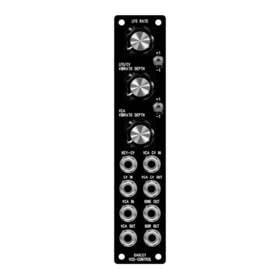
Oakley Sound Systems 5U Oakley Modular Series VCO Controller 1U wide oscillator master module User Manual V1.0.0 Tony Allgood B.Eng Oakley Sound Systems CARLISLE United Kingdom... - Page 2 The suggested panel for fitting to an Oakley modular system with the Oakley CV/gate buss. The twin keyboard control voltage (KCV) signals that this module generates are connected to the VCOs behind the front panel. If you do not have the facility for this you can make two of the front panel sockets carry the...
- Page 3 Introduction This is the User Manual for the issue 1 VCO Controller 5U module from Oakley Sound. This document contains a basic summary of its operation, how our Oakley Buss works, a guide to the front panel controls, how to connect it to your modules and finally calibration procedures.
- Page 4 CV (note control) and pin 3 carries gate (note on or off). The VCO Controller module taps into the Oakley buss and creates two new busses for each VCO bank. It also has a buss through feature for easy wiring The word buss is perhaps a little grand for something that has just two control lines and a single ground.
- Page 5 The Oakley VCO has a Oakley Buss input header on its socket board. Pin 1 of this header is connected to the NC lug of the 1V/octave input socket. So any voltage on pin 1 of this header is automatically connected to the module's 1V/octave input unless as jack is inserted into that socket.
- Page 6 Now play a few notes and ensure that the VCO is tracking nicely. If you do not have the Oakley Buss then you will have to make your connections with patch leads. Connect up your VCO so you can hear the output. Set it up so you can measure the frequency of the VCO with a guitar tuner or suitable VST plug-in in your DAW.
- Page 7 SCL2 – This trimmer sets the scale of the KCV2 output Repeat the above but with your second VCO and use the Key-CV2 output. The purpose of both SCL trimmers is to ensure that the VCO Controller adds nothing to the CV signal when the two depth pots are at their minimum settings and the switches are in their middle positions.
-
Page 8: Final Comments
I hope you enjoy using the Oakley VCO Controller. If you have any problems with the module, an excellent source of support is the Oakley Sound Forum at Muffwiggler.com. Paul Darlow and I are on this group, as well as many other users and builders of Oakley modules.