
Related Manuals for Cub Cadet Commercial 1536H


Summary of Contents for Cub Cadet Commercial 1536H
- Page 1 36", 48", 54" Hydrostatic Walk-Behind Commercial Rotary Mowers Standard and Wide Track(WT) Professional Turf Equipment OPERATOR’S AND SERVICE MANUAL...
-
Page 2: Table Of Contents
SECTION 1: TABLE OF CONTENTS FOREWORD .........................3 SAFETY PRECAUTIONS .....................4 SAFETY DECALS FOUND ON YOUR UNIT ..............5 SPECIFICATIONS......................7 OPERATING INSTRUCTIONS ..................8 CONTROLS ........................8 INITIAL ADJUSTMENTS....................10 BREAK-IN AND OPERATION..................11 CUTTING HEIGHT ADJUSTMENT TABLE ..............12 MAINTENANCE ......................13 TO CHANGE A BLADE:....................15 TO CHANGE THE BLADE DRIVE BELTS: ..............15 TO CHANGE THE PUMP DRIVE BELT:. -
Page 3: Foreword
The list of safety precautions should receive particular attention. This manual presents the operating and maintenance instructions necessary to keep your Cub Cadet Commercial mower at peak efficiency. If properly operated and maintained, your Cub Cadet Commercial mower will give dependable and trouble-free service. Although hazard control and accident... -
Page 4: Safety Precautions
SECTION 3: SAFETY PRECAUTIONS A. GENERAL: 1. Read this Operator’s Manual before starting the mower. Study the controls and learn the proper sequence of operation. 2. Do not allow anyone to operate or maintain this machine who has not read the manual. Never permit children to operate this machine. -
Page 5: Safety Decals Found On Your Unit
14. If you hit a solid object while mowing, disengage the blade clutch, place the ground speed control levers in neutral, place the neutral latch levers in the neutral lock position and stop the engine. Disconnect the spark plug wire and inspect for damage. - Page 6 SAFETY DECALS FOUND ON YOUR UNIT IF VALVE IS LEFT OPEN, CLOSE FUEL VALVE SEVERE ENGINE DAMAGE WHEN MACHINE IS OR HARD STARTING MAY NOT IN USE RESULT FROM FLOODING - TURN OFF ENGINE AND ALLOW WARNING TO COOL BEFORE REFUELING. - DO NOT SMOKE NEAR FUEL.
-
Page 7: Specifications
SECTION 5: SPECIFICATIONS POWER UNIT: MODEL 1536H 1548H 1748F 1954F Kawasaki Kawasaki Kawasaki Kawasaki Engine MFG 14HP 14HP 17HP 19HP Horsepower 4 Cycle 4 Cycle 4 Cycle 4 Cycle Type Single Single Twin Twin Starter Recoil Recoil Electric Electric Air Cleaner --------------- Dual Element, Dry ---------------- Lubrication --------------- Pressure with Filter ---------------... -
Page 8: Operating Instructions
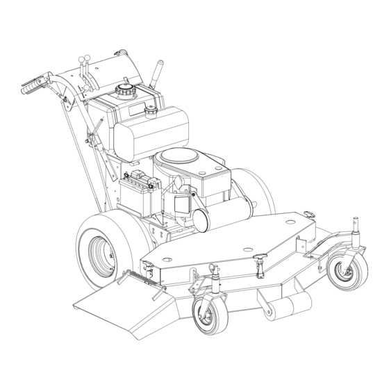
SECTION 6: OPERATING INSTRUCTIONS Choke Ground Speed Control Levers (Some Models) Electric Blade Ignition Clutch Neutral Switch Latch Lever Operator Presence Engine Lever Throttle/ Choke Left Traction Steering Lever Parking Brake Lever Standard Blade Clutch Figure 1 A. CONTROLS 1. Ignition Switch: Located in the center of the control panel between the handles. A clockwise 45° turn closes the ignition circuit. - Page 9 6. Neutral Latch Levers: Pivoted inside each handle there is a neutral latch lever which works with each of the traction/steering levers. When either of the traction/steering levers is squeezed and its neutral latch lever pushed forward and engaged in the neutral lock position, the traction/steering lever is held in a position where its pump should not be sending any oil to the wheel drive motor.
-
Page 10: Initial Adjustments
B. INITIAL ADJUSTMENTS 1. Disconnect the spark plug wire. 2. Check the tire pressure. Drive Wheels should be inflated to 25 psi. Caster Wheels should be inflated to 15 psi. Note: New tires are overinflated in order to properly seat the bead to the rim. 3. -
Page 11: Break-In And Operation
C. BREAK-IN AND OPERATION 1. Make certain you thoroughly understand all of the safety precautions before you attempt to operate this machine. 2. Check the engine oil level. Fill to the proper level with straight 30W engine oil rated for service SE or SF. 3. -
Page 12: Cutting Height Adjustment Table
the neutral latch levers into the neutral lock position. 13. Before moving into reverse, the mower’s forward motion should be completely stopped. 14. Practice operating the mower and as you gain confidence, move the ground speed selector levers forward to two thirds full speed. -
Page 13: Maintenance
SECTION 8: MAINTENANCE WARNING: Disconnect the spark plug wire to prevent the engine from accidentally starting before performing any maintenance on this mower. A. GENERAL MAINTENANCE: 1. If the mower must be tipped on its side for maintenance, first drain the fuel from the fuel tank, the oil from the engine’s crankcase and the hydraulic oil from the supply tank. - Page 14 100 hours and every 500 hours thereafter. The pumps and wheel drive motors are not owner repairable. If you have a problem with a pump or wheel drive motor, call your authorized Cub Cadet Commercial Dealer for a replacement. Do not disassemble the pump or wheel drive motor.
-
Page 15: To Change A Blade
G. MOWER MAINTENANCE 1. TO CHANGE A BLADE: a. Remove the deck cover. b. Tip the mower back and block up the front of the deck. See Figure 5. c. Place one wrench on the hex head bolt under the blade. Use a second wrench to remove the nut on top of the spindle pulley. - Page 16 d. Loosen the two belt guides under the engine deck and rotate them out of the way. Figure 7 e. Slip the long blade drive belt off of the pulleys. Loosen the idler pull rod which holds the idler pulley tight against the short blade drive belt. See Figure 7.
- Page 17 3. INSTALLATION AND REMOVAL OF MOWER FLOAT DECK 1. Power Unit Frame Tube 2. Stop Tabs 3. Mower Deck Channel 4. Retaining Pin 5. U-Bracket PREPARATION Place the mower deck in front of the power unit on a level surface. Turn off power take-off (PTO), turn off engine and remove key from ignition switch.
- Page 18 WARNING: Disengage PTO, stop engine and remove key to avoid accidental starting and injury. WARNING: When handling the mower deck, be careful not to cut yourself on the sharp blades. 1. Lift one side of the mower deck to achieve the desired cutting height. 2.
- Page 19 REMOVING THE MOWER DECK WARNING: Disengage PTO, stop engine and remove key to avoid accidental starting and injury. WARNING: When handling the mower deck cover, be careful not to cut yourself on the sharp blades. 1. Remove the center mower deck cover by first removing the two large wing nuts. 2.
-
Page 20: To Change The Pump Drive Belt
TO CHANGE THE PUMP DRIVE BELT: See Figure 8. a. Make sure the blade clutch is disengaged. Figure 8 b. Working under the engine deck, take the long blade drive belt off of the engine pulley. c. Loosen the locknut holding the pump drive belt idler pulley in place and slide the pulley away from the pump drive belt. -
Page 21: To Change Spindle Bearings (Fixed Decks Only)
6. TO CHANGE SPINDLE BEARINGS (Fixed Decks Only): (See the exploded view drawing on page 19.) a. Clamp the spindle assembly in a vise with the grease fitting pointing up. b. Bend down the tab of the tab lockwasher. c. Remove the hex jam nut. d. -
Page 22: Replacement Parts
SECTION 9: REPLACEMENT PARTS SPINDLE - Part No. 00057412 (Fixed Decks) Ref. Description Qty. Hex Jam Nut Tab Lockwasher Seal Spacer Top and Bottom Seal Bearing Spindle Housing Internal Spacer Cutter Blade Spindle Grease Fitting SPINDLE REPAIR KIT NO. 00054433 Ref. -
Page 23: Maintenance Record
MAINTENANCE RECORD DATE WORK PERFORMED DATE WORK PERFORMED... -
Page 24: Warranty
Cadet Commercial dealer subject to the above time and coverage limitations. Upon completion of your purchase, the Serial Number/s of the unit will be registered with the Cub Cadet. This will initiate and validate your limited warranty and the applicable Warranty Period.