Table of Contents
Advertisement
Copyright
©1998 by Toshiba Corporation. All rights reserved. Under the copyright laws, this manual cannot be
reproduced in any form without the prior written permission of Toshiba. No patent liability is assumed with
respect to the use of the information contained herein.
Toshiba Libretto 50CT/70CT Maintenance Manual
Third edition February 1998
Disclaimer
The information contained in this manual is subject to change without notice.
Toshiba Corporation and Toshiba America Information Systems, Inc., assume no liability for damages
incurred directly or indirectly from errors, omissions, or discrepancies in connection with the furnishing,
performance, or use of this material.
Trademarks
IBM is a registered trademark, and PC/AT, PS/2, OS/2 and VGA are trademarks of IBM Corporation.
MS-DOS and Windows are registered trademarks of Microsoft Corporation.
Intel and Pentium are registered trademarks, and MMX is a trademark of Intel Corporation.
Lotus is a registered trademark of Lotus Development Corporation.
Novell and NetWare are registered trademarks of Novell, Inc.
UNIX is a registered trademark of X/Open Company Ltd.
Sound Blaster and Pro are trademarks of Creative Technology Ltd.
Centronics is a registered trademark of Centronics Data Computer Corporation.
All other properties are trademarks or registered trademarks of their respective holders.
Libretto 50CT/70CT Maintenance Manual
i
Advertisement
Chapters
Table of Contents
Troubleshooting

Related Manuals for Toshiba Libretto 50CT


Summary of Contents for Toshiba Libretto 50CT
- Page 1 ©1998 by Toshiba Corporation. All rights reserved. Under the copyright laws, this manual cannot be reproduced in any form without the prior written permission of Toshiba. No patent liability is assumed with respect to the use of the information contained herein.
-
Page 2: Safety Precautions
NOTE: A “Note” contains general information that relates to safe maintenance services. Improper repair of the computer may result in safety hazards. Toshiba requires service technicians and authorized dealers or service providers to ensure that the following safety precautions are strictly adhered to. - Page 3 Chapter 4 Replacement Procedures describes the removal and replacement of the FRUs. Appendices The appendices describe the following: Handling the LCD module Board layout Pin assignments Key layout Wiring diagrams BIOS Rewrite Procedures Reliability Libretto 50CT/70CT Maintenance Manual...
- Page 4 Text that you are instructed to type in is shown in the boldface type below: DISKCOPY A: B: The display Text generated by the Libretto 50CT, that displays on the screen, is presented in the typeface below: Format complete System transferred...
-
Page 5: Table Of Contents
Pointing Device Troubleshooting ................2-24 Display Troubleshooting ..................2-25 Chapter 3 Tests and Diagnostics The Diagnostic Test....................3-1 Executing the Diagnostic Test.................3-3 Subtest Names ......................3-7 System Test ......................3-9 Memory Test ......................3-10 Keyboard Test ......................3-12 Display Test......................3-14 Floppy Disk Test....................3-17 Printer Test......................3-20 Libretto 50CT/70CT Maintenance Manual... - Page 6 Optional Memory Module..................4-12 Keyboard ......................4-14 Display Assembly....................4-16 RTC Battery ......................4-19 System Board .......................4-20 4.10 Display Mask ......................4-21 4.11 FL Inverter Board....................4-23 4.12 LCD Module ......................4-25 4.13 Power Switch Board .....................4-27 4.14 AccuPoint Board ....................4-29 4.15 LCD Flexible Cable....................4-31 Libretto 50CT/70CT Maintenance Manual...
- Page 7 Appendix A Handling the LCD Module ................A-1 Appendix B Board Layout....................B-1 Appendix C Pin Assignments.................... C-1 Appendix D Key Layouts ....................D-1 Appendix E Wiring Diagrams ................... E-1 Appendix F BIOS Rewrite Procedures................F-1 Appendix G Reliability......................G-1 Libretto 50CT/70CT Maintenance Manual...
- Page 8 Libretto 50CT/70CT Maintenance Manual...
- Page 9 TOSHIBA Toshiba America Information Systems, Inc. Computer Systems Division 9740 Irvine Boulevard Irvine, CA 92618...
-
Page 10: Chapter 1 Hardware Overview
Chapter 1 Hardware Overview... - Page 11 1-ii Libretto 50CT/70CT Maintenance Manual...
- Page 12 Figure 1-3 System unit block diagram................1-4 Figure 1-4 3.5-inch FDD ....................1-7 Figure 1-5 2.5-inch HDD....................1-8 Figure 1-6 Keyboard......................1-9 Figure 1-7 LCD module....................1-10 Tables Table 1-1 FDD specifications.....................1-7 Table 1-2 HDD specifications....................1-8 Table 1-3 Keyboard specifications ..................1-9 Table 1-4 LCD specifications...................1-10 Libretto 50CT/70CT Maintenance Manual 1-iii...
- Page 13 Table 1-5 FL inverter board specifications ...............1-11 Table 1-6 Power supply board output rating ..............1-12 Table 1-7 Battery specifications..................1-13 Table 1-8 Time required for quick charge ................1-14 Table 1-9 RTC battery charging/data preservation time............1-14 1-iv Libretto 50CT/70CT Maintenance Manual...
-
Page 14: Features
The following features and benefits are incorporated: Microprocessor The Libretto 50CT has a 64-bit microprocessor, Intel Pentium processor running at a clock speed of 75MHz. The Libretto 70CT has a 64-bit microprocessor, Intel Pentium processor with MMX technology running at a clock speed of 120MHz. - Page 15 The sound system is equipped with a built-in speaker and stereo headphone jack. q External Floppy Disk Drive (FDD) (Option) A 3.5-inch external FDD is connected to the PC card slot and accommodates both 2HD (1.44MB) and 2DD (720KB) disks. Libretto 50CT/70CT Maintenance Manual...
-
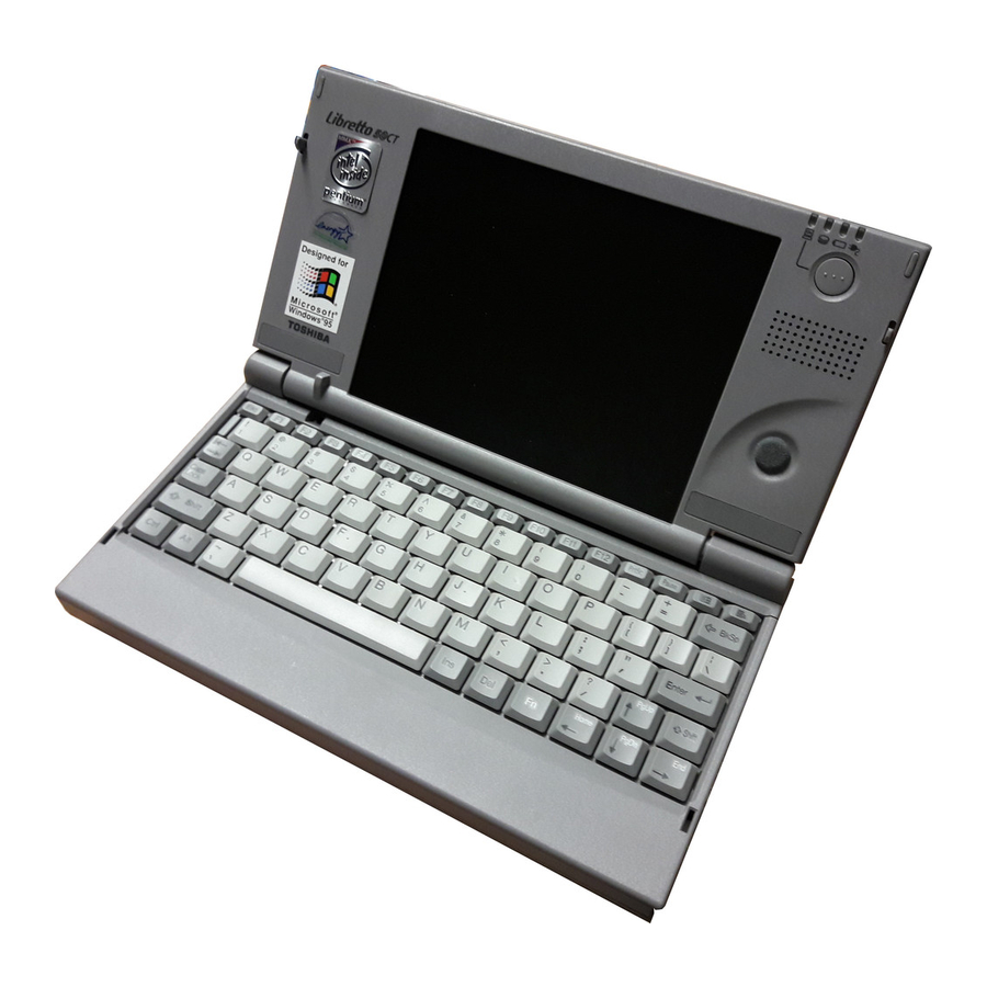
Page 16: Figure 1-1 Front Of The Computer
1 Hardware Overview 1.1 Features The front of the computer is shown in Figure 1-1. Figure 1-1 Front of the computer The system unit configuration is shown in Figure 1-2. Figure 1-2 System unit configuration Libretto 50CT/70CT Maintenance Manual... -
Page 17: System Unit Block Diagram
1.2 System Unit Block Diagram 1 Hardware Overview System Unit Block Diagram Figure 1-3 is a block diagram of the system unit. Figure 1-3 System unit block diagram Libretto 50CT/70CT Maintenance Manual... - Page 18 The system unit is composed of the following major components: q Microprocessor Libretto 50CT: Intel 75 MHz Pentium processor operates at 2.9/3.3 volts and incorporates the math co-processor and 16 KB cache memory. Libretto 70CT: Intel 120 MHz Pentium processor with MMX technology operates at 2.9/3.3 volts and incorporates the math co-processor and 16 KB cache memory.
- Page 19 I/O card control BIOS-ROM interface Infrared port control Sound control q Keyboard Controller (KBC) This KBC includes: the keyboard scan controller and keyboard interface controller; and controls: the internal keyboard, external keyboard, IPS and PS/2 mouse. Libretto 50CT/70CT Maintenance Manual...
- Page 20 Provides simultaneous control of both an AccuPoint and a PS/2 mouse. q Sound Controller The Libretto 50CT uses one OPL3-SA2 that incorporates: OPL3 FM synthesizer, Digital Analog Converter (DAC), and MPU401 MIDI interface. The Libretto 70CT uses one OPL3-SA3 that incorporates: OPL3 FM synthesizer, Digital Analog Converter (DAC), and MPU401 MIDI interface.
-
Page 21: Inch External Fdd (Option)
1,000 Formatted 1,440 Number of heads Number of cylinders Access time (ms) Track to track Average Head settling time Recording track density (tpi) Data transfer rate (Kbps) Rotation speed (rpm) Recording method Modified Frequency Modulation (MFM) Libretto 50CT/70CT Maintenance Manual... -
Page 22: Inch Hdd
The removable HDD is a random access non-volatile storage device. It has a non-removable 2.5-inch magnetic disk and mini-winchester type magnetic heads. The Libretto 50CT computer supports a 815MB HDD. The Libretto 70CT computer supports a 1.58GB HDD. The HDD is shown in Figure 1-5. -
Page 23: Table 1-2 Hdd Specifications
1.4 2.5-inch HDD 1 Hardware Overview The specifications for the HDDs are listed in Table 1-2. Table 1-2 HDD specifications Libretto 50CT: 815MB HDD Item Specifications Formatted capacity (MB) Number of disks Logical heads Bytes per sector Rotation speed (rpm) -
Page 24: Keyboard
See Appendix D for optional keyboard configurations. Figure 1-6 Keyboard The specifications for the keyboard are listed in Table 1-3. Table 1-3 Keyboard specifications Item Specifications Input method Pantograph (Function keys use cylinders) Pitch 15mm Thickness Libretto 50CT/70CT Maintenance Manual 1-11... -
Page 25: Lcd Panel
122.8(H)x92.16(V) Contrast 100:1 FL current (mA) 4.6/4.0/2.8/2.4* (Bright/Semi-bright) *NOTE: The FL currents at power on are: Bright Semi-bright Universal AC Adapter connected 4.6 mA 2.8 mA Universal AC Adapter not connected 4.0 mA 2.4 mA 1-12 Libretto 50CT/70CT Maintenance Manual... -
Page 26: Fl Inverter Board
Power Output Voltage (Vrms) Current (mA) (4.6/4.0/2.8/2.4)* (Bright/Semi-bright) *NOTE: The FL currents at power on are: Bright Semi-bright Universal AC Adapter connected 4.6 mA 2.8 mA Universal AC Adapter not connected 4.0 mA 2.4 mA Libretto 50CT/70CT Maintenance Manual 1-13... -
Page 27: Power Supply
The power supply output rating is specified in Table 1-6. Table 1-6 Power supply board output rating Regulation Name voltage (V) tolerance (%) CPU, RAM, GA, +3.3 ±5 VGA, VRAM GA, BIOS ROM, +12.0 ±5 KBC, PC card 1-14 Libretto 50CT/70CT Maintenance Manual... -
Page 28: Batteries
The system charges the battery using quick charge or trickle charge. q Quick Battery Charge The battery quick charges when the Universal AC Adapter is connected and the system is powered off or in stand-by mode. Libretto 50CT/70CT Maintenance Manual 1-15... - Page 29 Table 1-9 shows the charging time and data preservation period of the RTC battery. Table 1-9 RTC battery charging/data preservation time Item Time Charging Time 48 hours Data preservation period (full charge) About 1 month 1-16 Libretto 50CT/70CT Maintenance Manual...
-
Page 30: Troubleshooting Procedures
Chapter 2 Troubleshooting Procedures... - Page 31 2-ii Libretto 50CT/70CT Maintenance Manual...
- Page 32 2.8 Pointing Device Troubleshooting ................2-24 Procedure 1 Diagnostic Test Program Execution Check .........2-24 Procedure 2 Connector and Replacement Check..........2-24 2.9 Display Troubleshooting....................2-25 Procedure 1 Diagnostic Test Program Execution Check .........2-25 Procedure 2 Connector Check................2-25 Procedure 3 Replacement Check ..............2-25 Libretto 50CT/70CT Maintenance Manual 2-iii...
- Page 33 Table 2-3 Printer port LED boot mode status (1/2)............2-13 Table 2-4 Printer port LED Hibernation mode error status..........2-15 Table 2-5 FDD error codes and statuses ................2-17 Table 2-6 Hard disk drive error codes and statuses ............2-22 2-iv Libretto 50CT/70CT Maintenance Manual...
-
Page 34: Troubleshooting Overview
The following tools are necessary for implementing the troubleshooting procedures: 1. Diagnostics disk 2. Phillips screwdriver (2 mm) 3. Toshiba MS-DOS system disk(s) (You must install the following onto the disk: SYS.COM, FORMAT.COM,FDISK.COM and FDISK.EXE) 4. 2DD or 2HD formatted work disk for floppy disk drive testing 5. -
Page 35: Troubleshooting Flowchart
Use the flowchart in figure 2-1 as a guide to determine which troubleshooting procedures to execute. Before going through the flowchart steps, do the following: q Verify with the customer that Toshiba Windows 95 is installed on the hard disk. Non- Toshiba operating systems can cause the computer to malfunction. -
Page 36: Troubleshooting Flowchart
2 Troubleshooting Procedures 2.2 Troubleshooting Flowchart Figure 2-1 Troubleshooting flowchart (1/2) Libretto 50CT/70CT Maintenance Manual... - Page 37 4. If an error is detected on the keyboard test, do the Keyboard troubleshooting procedures in Section 2.7. 5. If an error is detected on the display test, do the Display troubleshooting procedures in Section 2.9. Libretto 50CT/70CT Maintenance Manual...
-
Page 38: Power Supply Troubleshooting
Blinks orange Power supply malfunction Blinks green Stand-by state Doesn’t light Any condition other than those above *3 When the power supply controller detects a malfunction, the DC IN icon blinks and an error code is displayed. Libretto 50CT/70CT Maintenance Manual... -
Page 39: Power Supply Troubleshooting
If the Battery icon does not light orange or green, go to Procedure 4. CAUTION: Use only an AC adapter that is manufactured specifically for the Libretto 50CT/70CT. If you use a different AC adapter, the computer’s power supply may malfunction or a fuse on the system board may be blown. - Page 40 Power supply microcontroller Error code Meaning Firmware or program error q CPU environmental condition Error code Meaning CPU temperature is outside the allowable range CPU overheat (The CPU heat sensor has detected overheating and has automatically shut down) Libretto 50CT/70CT Maintenance Manual...
- Page 41 If the error still exists, go to Procedure 4. Check 5 If error code 11h displays: q Go to Procedure 3. Check 6 For any other error, go to Procedure 4. Libretto 50CT/70CT Maintenance Manual...
- Page 42 Replace the AC adapter with a new one. If the problem still exists, go to Check 2. Check 2 Replace the system board with a new one. Refer to Chapter 4 for instructions on how to remove and replace the system board. Libretto 50CT/70CT Maintenance Manual...
-
Page 43: System Board Troubleshooting
If an error message is shown on the display, perform Check 1. q If there is no error message, go to Procedure 2. q If Toshiba MS-DOS or Toshiba Windows 95 is properly loaded, go to Procedure 3. Check 1 If one of the following error messages displays on the screen, press the F1 key as instructed. -
Page 44: System Board Troubleshooting
(9) SYSTEM MEMORY ERROR (10) SYSTEM MEMORY PARITY ERROR (11) EXTENDED MEMORY ERROR (12) EXTENDED MEMORY PARITY ERROR (13) DMA PAGE REGISTER ERROR (14) DMAC #1 ERROR (15) DMAC #2 ERROR (16) PIC #1 ERROR Libretto 50CT/70CT Maintenance Manual 2-11... - Page 45 4. Convert the status from binary to hexadecimal notation. 5. If the final LED status is FFh (normal status), go to Procedure 3. 6. If the final LED status matches any of the test status values in Table 2-3, do Check 1. 2-12 Libretto 50CT/70CT Maintenance Manual...
- Page 46 VRAM ERROR System memory test SYSTEM MEMORY ERROR SYSTEM MEMORY PARITY ERROR Extended memory test EXTENDED MEMORY ERROR EXTENDED MEMORY PARITY ERROR DMA page register test DMA PAGE REGISTER ERROR DMAC test DMAC #X ERROR Libretto 50CT/70CT Maintenance Manual 2-13...
- Page 47 2.5. Procedure 3 Printer Port LED Check in Hibernation Mode The printer port LED displays the IRT status and test status by turning lights on and off as an eight-digit binary value for Hibernation mode. 2-14 Libretto 50CT/70CT Maintenance Manual...
- Page 48 Real Timer test (9) NDP test (10) Expansion test (11) Sound test (12) If an error is detected during these tests, replace the System Board with a new one. If the problem still exists, go to Procedure 5. Libretto 50CT/70CT Maintenance Manual 2-15...
- Page 49 2 Troubleshooting Procedures Procedure 5 Connection Check Check each cable connection shown in Figure 2-3, then retry the computer’s operation. If the problem still exists, another I/O interface may be faulty. Figure 2-3 Cable connection diagram 2-16 Libretto 50CT/70CT Maintenance Manual...
-
Page 50: Floppy Disk Drive (Fdd) Troubleshooting
Address mark not found Write protected Record not found Media removed on dual attach card DMA overrun error DMA boundary error CRC error FDC error Seek error FD not in drive Time out error (Not ready) Libretto 50CT/70CT Maintenance Manual 2-17... -
Page 51: Floppy Disk Drive (Fdd) Troubleshooting
2.5 Floppy Disk Drive (FDD) Troubleshooting 2 Troubleshooting Procedures Write buffer error 2-18 Libretto 50CT/70CT Maintenance Manual... - Page 52 The FDD may be defective or damaged. Replace the FDD with a new one. If the FDD is still not functioning properly, perform Check 3. Check 3 Replace the system board with a new one following the steps in Chapter 4, Replacement Procedures. Libretto 50CT/70CT Maintenance Manual 2-19...
-
Page 53: Hard Disk Drive (Hdd) Troubleshooting
Refer to the operating system instructions. Procedure 1 Partition Check Insert the Toshiba MS-DOS system disk, turn the computer on, then perform the following checks: Check 1 Type C: and press Enter. If you cannot change to drive C, go to Check 2. If you can, go to Procedure 2. -
Page 54: Procedure 2 Message Check
Non-System disk or disk error Replace and press any key Check 3 Use the Toshiba MS-DOS system disk to install a system program on the hard disk, using the SYS command. If the following message displays, the system program has been transferred to the HDD. - Page 55 2.6 Hard Disk Drive (HDD) Troubleshooting 2 Troubleshooting Procedures Check 2 Use the Toshiba MS-DOS system disk to partition the hard disk, using the FDISK command. Check 3 Using the Diagnostic Disk, format the HDD with a low level format option. Refer to Chapter 3, Tests and Diagnostics for more information about the diagnostics program.
- Page 56 Replace the HDD unit with a new one following the instructions in Chapter 4, Replacement Procedures. If the HDD is still not functioning properly, do Check 2. Check 2 Replace the system board with a new one following the instructions in Chapter 4. Libretto 50CT/70CT Maintenance Manual 2-23...
-
Page 57: Keyboard Troubleshooting
Do Procedure 1 again. If the error still exists, go to Check 2. Check 2 The system board may be damaged. Replace the system board with a new one. Refer to Chapter 4 for more information. Libretto 50CT/70CT Maintenance Manual 2-23... -
Page 58: Pointing Device Troubleshooting
If there is a problem with the pointing device, disassemble the computer as described in Chapter 4, Replacement Procedures, and do Check Check 1 The AccuPoint board or flat cables may be damaged. Replace the AccuPoint board or flat cables with new ones. 2-24 Libretto 50CT/70CT Maintenance Manual... -
Page 59: Display Troubleshooting
If some screen functions do not operate properly, go to Check 3. Check 1 Replace the LCD flat cable with a new one and test the display again. If the problem still exists, go to Check 2. Libretto 50CT/70CT Maintenance Manual 2-25... - Page 60 Replace the FL with a new one and test the display again. If the problem still exists, go to Check 5. Check 5 The system board may be damaged. Replace the system board with a new one. 2-26 Libretto 50CT/70CT Maintenance Manual...
-
Page 61: Chapter 3 Tests And Diagnostics
Chapter 3 Tests and Diagnostics... - Page 62 3-ii Libretto 50CT/70CT Maintenance Manual...
- Page 63 3.19 Head Cleaning ......................3-41 3.19.1 Function Description ................3-41 3.19.2 Operations...................3-41 3.20 Log Utilities......................3-42 3.20.1 Function Description ................3-42 3.20.2 Operations...................3-42 3.21 Running Test ......................3-44 3.21.1 Function Description ................3-44 3.21.2 Operations...................3-44 3.22 Floppy Disk Drive Utilities..................3-45 3.22.1 Function Description ................3-45 Libretto 50CT/70CT Maintenance Manual 3-iii...
- Page 64 3.22.2 Operations...................3-45 3-iv Libretto 50CT/70CT Maintenance Manual...
- Page 65 Tables Table 3-1 Subtest names (1/2) ...................3-7 Table 3-2 Error codes and error status names (1/3)............3-32 Table 3-3 Hard disk controller status register contents.............3-35 Table 3-4 Error register contents ..................3-36 Table 3-5 Hard disk formatting sequence.................3-37 Libretto 50CT/70CT Maintenance Manual...
-
Page 66: The Diagnostic Test
MEMORY TEST q KEYBOARD TEST q DISPLAY TEST q FLOPPY DISK TEST q PRINTER TEST q ASYNC TEST q HARD DISK TEST q REAL TIMER TEST q NDP TEST q EXPANSION TEST q SOUND TEST Libretto 50CT/70CT Maintenance Manual... - Page 67 Serial port direct cable The following sections detail the tests within the Diagnostic Test function of the DIAGNOSTIC TEST MENU. Refer to Sections 3.19 through 3.24 for detailed information on the remaining Service Program Module functions. Libretto 50CT/70CT Maintenance Manual...
-
Page 68: Executing The Diagnostic Test
3.2 Executing the Diagnostic Test Executing the Diagnostic Test Toshiba MS-DOS is required to run the Diagnostics Program. To start the Diagnostics Program follow these steps: 1. Connect a wraparound connector to the I/O adapter printer port and RS-232C port. - Page 69 3. To execute the Diagnostic Test Menu from the Diagnostics Menu, set the highlight bar to 1, and press Enter. The following Diagnostic Test Menu displays: TOSHIBA personal computer xxx DIAGNOSTICS version X.XX (c) copyright TOSHIBA Corp. 19XX DIAGNOSTIC TEST MENU : 1 - SYSTEM TEST...
- Page 70 Select YES for ERROR STOP to stop the test program when an error is found and display the operation guide on the right side of the display screen as shown below: ERROR STATUS NAME [[ HALT OPERATION ]] 1: Test end 2: Continue 3: Retry Libretto 50CT/70CT Maintenance Manual...
- Page 71 Select NO for ERROR STOP to keep the test running even if an error is found. Table 3-1 in Section 3.3 lists the function of each test on the subtest menu. Table 3-2 in Section 3.16 lists the codes and statuses for each error. Libretto 50CT/70CT Maintenance Manual...
-
Page 72: Subtest Names
Gradation for VGA Gradation for LCD Gradation & mode test for VGA All dots on/off for LCD “H” pattern display Sequential read Sequential read/write Random address/data Write specified address Read specified address PRINTER Ripple pattern Function Wraparound Libretto 50CT/70CT Maintenance Manual... - Page 73 Cross talk & peak shift Write/read/compare (CE) Write specified address Read specified address ECC circuit Sequential write W-R-C specified address REAL TIMER Real time Backup memory Real time carry NDP test EXPANSION PCMCIA wraparound SOUND FM synthesizer SINE-wave playback Libretto 50CT/70CT Maintenance Manual...
-
Page 74: System Test
The System Test contains one test that tests the system. Move the highlight bar to the subtest you want to execute and press Enter. Subtest 01 ROM checksum This subtest executes a checksum test of the BIOS ROM on the system board. Libretto 50CT/70CT Maintenance Manual... -
Page 75: Memory Test
Subtest 04 Protected mode This subtest writes constant data and address data to extended memory (maximum address 100000h), then reads the new data and compares the result with the original data. 3-10 Libretto 50CT/70CT Maintenance Manual... - Page 76 (‘7000’:’Program’ size to ‘7000’:’7FFF’ (32 KB)) to check the hit-miss ratio (on/off status) for CPU cache memory. One test takes 3 seconds. Number of misses Number of hits Number of misses Number of hits Fail Libretto 50CT/70CT Maintenance Manual 3-11...
-
Page 77: Keyboard Test
PS/2 mouse connect check NOTE: To execute the PS/2 mouse connect check, a PS/2 mouse must be connected to the computer before the power is turned on. This subtest checks whether a PS/2 mouse is connected. 3-12 Libretto 50CT/70CT Maintenance Manual... - Page 78 <BUTTON> display alternates between black and white. Also, the parameters appear on the right side of the display. If two IPS switches are pressed at the same time, the subtest menu is displayed. Libretto 50CT/70CT Maintenance Manual 3-13...
-
Page 79: Display Test
To exit this subtest and return to the DISPLAY TEST menu, press Ctrl + Break. Subtest 03 Gradation for LCD This subtest displays eight colors: red, semi-red, green, semi-green, blue, semi- blue, white, and semi-white. Each color displays full screen for three seconds. 3-14 Libretto 50CT/70CT Maintenance Manual... - Page 80 640 x 480 3, 12, 13 The image below displays on the screen when this subtest executes. Pressing Enter changes the size of the displayed image. Pressing Enter changes the size of the displayed image. Libretto 50CT/70CT Maintenance Manual 3-15...
- Page 81 This subtest displays a full screen of “H” patterns. HHHHHHHHHHHHHHHHHHHHHHHHHHHHHHHHHHHHHHHHHHHHHHH HHHHHHHHHHHHHHHHHHHHHHHHHHHHHHHHHHHHHHHHHHHHHHH HHHHHHHHHHHHHHHHHHHHHHHHHHHHHHHHHHHHHHHHHHHHHHH HHHHHHHHHHHHHHHHHHHHHHHHHHHHHHHHHHHHHHHHHHHHHHH HHHHHHHHHHHHHHHHHHHHHHHHHHHHHHHHHHHHHHHHHHHHHHH HHHHHHHHHHHHHHHHHHHHHHHHHHHHHHHHHHHHHHHHHHHHHHH HHHHHHHHHHHHHHHHHHHHHHHHHHHHHHHHHHHHHHHHHHHHHHH HHHHHHHHHHHHHHHHHHHHHHHHHHHHHHHHHHHHHHHHHHHHHHH HHHHHHHHHHHHHHHHHHHHHHHHHHHHHHHHHHHHHHHHHHHHHHH HHHHHHHHHHHHHHHHHHHHHHHHHHHHHHHHHHHHHHHHHHHHHHH HHHHHHHHHHHHHHHHHHHHHHHHHHHHHHHHHHHHHHHHHHHHHHH HHHHHHHHHHHHHHHHHHHHHHHHHHHHHHHHHHHHHHHHHHHHHHH HHHHHHHHHHHHHHHHHHHHHHHHHHHHHHHHHHHHHHHHHHHHHHH To exit this subtest and return to the DISPLAY TEST menu, press Ctrl + Break. 3-16 Libretto 50CT/70CT Maintenance Manual...
-
Page 82: Floppy Disk Test
02 - Sequential read/write 03 - Random address/data 04 - Write specified address 05 - Read specified address 99 - Exit to DIAGNOSTIC TEST MENU Exit to DIAGNOSTIC TEST MENU Select items Enter Specify Exit Libretto 50CT/70CT Maintenance Manual 3-17... - Page 83 Test Menu. Refer to step 3 at the beginning of this section to set the start track. Subtest 02 Sequential read/write This subtest continuously writes data pattern B5ADADh to all the specified tracks selected in Subtest 01. The data is then read and compared to the original data. 3-18 Libretto 50CT/70CT Maintenance Manual...
- Page 84 Subtest 01. The data is then read and compared to the original data. Subtest 04 Write specified address This subtest writes specified data to a specified track, head, and address. Subtest 05 Read specified address This subtest reads data from a specified track, head, and address. Libretto 50CT/70CT Maintenance Manual 3-19...
-
Page 85: Printer Test
Subtest 01 or 02, the test will automatically start after you press Enter. Subtest 01 Ripple pattern This subtest prints characters for codes 20h through 7Eh line-by-line while shifting one character to the left at the beginning of each new line. 3-20 Libretto 50CT/70CT Maintenance Manual... - Page 86 The parallel port wraparound connector (34M741986G01) wiring diagram is described in Appendix E. This subtest checks the output and bi-directional modes of the data control and the status of lines through the printer wraparound connector. Libretto 50CT/70CT Maintenance Manual 3-21...
-
Page 87: Async Test
“receive” (Subtest 03). The wiring diagram for the serial port direct cable is described in Appendix E. This subtest sends 20h through 7Eh data to the receive side, then receives the sent data and compares it to the original data. 3-22 Libretto 50CT/70CT Maintenance Manual... - Page 88 This subtest checks the data send/receive function through the Infra_red port. Subtest 06 Infra_red transmit mode This subtest checks the data send function through the Infra_red port. Subtest 07 Infra_red receive mode This subtest checks the data receive function through the Infra_red port. Libretto 50CT/70CT Maintenance Manual 3-23...
-
Page 89: Hard Disk Test
The HDD status is described in Section 3.18. Select yes or no. Detail status display 5. The Hard Disk Test message will display when you select the number of the subtest you want to execute and press Enter. The following message displays during each subtest. 3-24 Libretto 50CT/70CT Maintenance Manual... - Page 90 This subtest writes unique address data to each sector of the HDD track-by- track. The data written to each sector is then read and compared with the original data. There are three ways the HDD can be read: Forward sequential Reverse sequential Random Libretto 50CT/70CT Maintenance Manual 3-25...
- Page 91 This subtest writes specified 2-byte data to all of the cylinders on the HDD. Subtest 10 W-R-C specified address This subtest writes data to a specified cylinder and head on the HDD, then reads the data and compares it to the original data. 3-26 Libretto 50CT/70CT Maintenance Manual...
-
Page 92: Real Timer Test
Writes 1-bit of “off” data to addresses FEh, FB, FD through 7Fh Writes the data patterns AAh and 55h to 50-byte memory (addresses 0Eh to 7Fh) The subtest reads and compares this data with the original data. To exit, press Ctrl + Break. Libretto 50CT/70CT Maintenance Manual 3-27... - Page 93 Current date : 12-31-1995 Current time : 23:59:58 Press Enter to display the following: Current date : 01-01-1996 Current time : 00:00:00 PRESS [Enter] KEY TO EXIT TEST Press Ctrl + Break to exit. 3-28 Libretto 50CT/70CT Maintenance Manual...
-
Page 94: Ndp Test
The NDP test contains one subtest that tests the NDP functions. Subtest 01 NDP Test This test checks the following functions of the coprocessor: q Control word q Status word q Bus q Addition q Multiplication Press Ctrl + Break to exit. Libretto 50CT/70CT Maintenance Manual 3-29... -
Page 95: Expansion Test
00001 Address line 00001 REG#, CE#1, CE#2 nn=A0, 90, 80, 00 00002 Data line ww=write data,rr=read data 00003 –– –– Speaker line 00004 40, 80 Wait line (40<xx<80) 00005 Other lines (BSY#, BVD1) nn=21, 00 3-30 Libretto 50CT/70CT Maintenance Manual... -
Page 96: Sound Test
Load the COM file. This subtest expands the sine-wave data table to 64KB and creates sine-wave data. The play data is transferred between DMA and CODEC, and plays the sound. (It is a long beep.) Use the oscilloscope to observe the sine-wave form. Libretto 50CT/70CT Maintenance Manual 3-31... -
Page 97: Error Codes And Error Status Names
FDD Not In Drive Error Time Out Error Write Buffer Error Printer Time Out Fault Select Line Out of Paper Power Off Busy Line ASYNC DSR On Time Out CTS On Time Out RX-READY Time Out 3-32 Libretto 50CT/70CT Maintenance Manual... - Page 98 ECC Recover Enabled HDC Error Seek Error Time Out Error Drive Not Ready Undefined Error Write Fault Status Error Access Time Out Error No Co-Processor Control Word Error Status Word Error Bus Error Addition Error Multiply Error Libretto 50CT/70CT Maintenance Manual 3-33...
- Page 99 Table 3-2 Error codes and error status names (3/3) Device name Error code Error status name PCMCIA Address Line Error REG# Line Error CE#1 Line Error CE#2 Line Error DATA Line Error WAIT Line Error BSY# Line Error BVD1 Line Error No PCMCIA 3-34 Libretto 50CT/70CT Maintenance Manual...
-
Page 100: Hard Disk Test Detail Status
“0” — Not used CORR (Corrected “1” — Correctable data error is corrected data) “0” — Not used “1” — Index is sensed (Index) “0” — Normal “1” — The previous command was terminated with some error (Error) Libretto 50CT/70CT Maintenance Manual 3-35... - Page 101 “1” — Illegal command error or a drive status error occurs “0” — The hard disk has found track 0 during a recalibrate TK00 command “1” — The hard disk could not find track 0 during a recalibrate (Track 0) command —— Not used 3-36 Libretto 50CT/70CT Maintenance Manual...
-
Page 102: Hard Disk Format
NOTE: Before executing the all track format option, check for bad tracks using the Bad Track CHECK option or display a list of bad tracks on the HDD. Table 3-5 Hard disk formatting sequence Items (MT800) Storage capacity Heads Bytes per sector Rotation speed (rpm) 4,000 Libretto 50CT/70CT Maintenance Manual 3-37... - Page 103 NOTE: After the HDD has been formatted, execute the Toshiba MS-DOS FDISK command, to partition the HDD. Next, execute the Toshiba MS-DOS FORMAT command. Refer to the Toshiba MS-DOS manual for more information about using these commands. Select 2 and press Enter on the Diagnostic Menu, to display the following messages: DIAGNOSTICS - HARD DISK FORMAT : VX.XX...
- Page 104 (e) Track verification A check is made of all tracks and if an ECC error, ECC correctable data error or record-not-found error is detected at a track, that track is automatically formatted as a bad track. Libretto 50CT/70CT Maintenance Manual 3-39...
- Page 105 Drive number select (1:#1, 2:#2) ? Bad tracks will display in the format shown below. [[cylinder, head = 0123 03]] Press Enter to return to the Hard Disk Format menu. 3-40 Libretto 50CT/70CT Maintenance Manual...
-
Page 106: Head Cleaning
2. Remove the Diagnostics Disk from the FDD, insert the cleaning disk, and press Enter. 3. When the “cleaning start” message displays, the FDD head cleaning has begun. 4. The display automatically returns to the Diagnostic Menu when the program is completed. Libretto 50CT/70CT Maintenance Manual 3-41... -
Page 107: Log Utilities
10. Error status name (STATUS NAME) 3.20.2 Operations 1. Select 5 and press Enter on the Diagnostic Menu to log error information into RAM or onto a floppy disk. The error information displays in the following format: 3-42 Libretto 50CT/70CT Maintenance Manual... - Page 108 The 7 key writes the log information to a floppy disk. 3. In the case of “error retry OK,” a capital “R” will be placed at the beginning of the error status. However, it is not added to the error count. Libretto 50CT/70CT Maintenance Manual 3-43...
-
Page 109: Running Test
Mount the work disk(s) on the drive(s), then press [Enter] key. [Warning : The contents of the disk(s), will be destroyed.] 5. This program is executed continuously. To terminate the program, press Ctrl + Break. 3-44 Libretto 50CT/70CT Maintenance Manual... -
Page 110: Floppy Disk Drive Utilities
FDD and HDD. 1. FORMAT NOTE: This program is only for testing a floppy disk drive. The option is different from the Toshiba MS-DOS FORMAT command. (a) This program can format a 5.25-inch or 3.5-inch floppy disk in the following formats: 2DD: Double-sided, double-density, double-track, 96/135 TPI, MFM mode, 512 bytes, 9 sectors/track. - Page 111 FLOPPY DISK FORMAT & COPY : VX.XX Type select (0:2DD,3:2HD) ? (b) Select a media/drive type number to display a message similar to the one below: Insert source disk into drive A: Press any key when ready. 3-46 Libretto 50CT/70CT Maintenance Manual...
- Page 112 If 2 is selected, the following message displays: Select drive number (1:C, 2:D) ? After selecting the HDD, the display will go to step (f). (c) The following message displays: Format type select (1:2DD, 2:2D, 3:2HD) Libretto 50CT/70CT Maintenance Manual 3-47...
- Page 113 — Max. address — [Track ] = xxx [ Head ] = xx [Sector] = xx Track number ?? (f) Set the track number you want to dump. The system will access the disk and dump a list. 3-48 Libretto 50CT/70CT Maintenance Manual...
-
Page 114: System Configuration
- 1 ASYNC ADAPTER - 1 HARD DISK DRIVE(S) - 1 PRINTER ADAPTER - XXXMB EXTENDED MEMORY - 1 MATH CO-PROCESSOR - CPU CLOCK = P75MHz Press [Enter] Key Press Enter to return to the Diagnostic Menu. Libretto 50CT/70CT Maintenance Manual 3-49... -
Page 115: Setup
(d) Sound System 6. Others (a) Power-up Mode (b) CPU Cache (c) System Auto Off (d) Alarm Volume (e) System Beep (f) Panel Power On/Off (g) Alarm Power On (h) Pointing Devices (i) Boot Priority 3-50 Libretto 50CT/70CT Maintenance Manual... -
Page 116: Accessing The Setup Program
Space, BkSp : Change values Esc: Exit without saving Home: Set default values End: Save changes and Exit NOTE: The Panel Power On/Off and System Auto Off items appear only when the computer is in Hibernation mode. Libretto 50CT/70CT Maintenance Manual 3-51... - Page 117 3.24.5 The Factory Preset Configuration When you access SETUP, the current configuration displays. 1. To show the factory preset configuration, press Home. 2. To accept the default settings, press End and then press Y. 3-52 Libretto 50CT/70CT Maintenance Manual...
- Page 118 These options configure the computer’s display. (a) Display Adapter Enables or disables the internal controller for the VGA internal display. VGA compatible Enables the internal VGA controller. (Default) Not Used Disables the internal VGA controller. Libretto 50CT/70CT Maintenance Manual 3-53...
- Page 119 (d) VGA Segment Address E4000h (Default) C0000h E0000h (e) Text Mode Stretch Text Mode Stretch enables a larger display area of the screen. Enabled Enables the LCD display stretch feature. Disabled Disables the LCD display stretch feature. (Default) 3-54 Libretto 50CT/70CT Maintenance Manual...
- Page 120 (a) Serial Port This option allows you to set the COM level for the serial port. The serial port interrupt request level (IRQ) and I/O port base address for each COM level are shown below: Libretto 50CT/70CT Maintenance Manual 3-55...
- Page 121 When you select one of the above options, except for Not used, a subwindow similar to the one below displays to let you set the infrared port mode. The options for this setting are IrDA Compatible (default) and ASK. OPTION Mode IrDA Compatible 3-56 Libretto 50CT/70CT Maintenance Manual...
- Page 122 The options for this setting are ECP (default) and Std. Bi-Directional. OPTIONS Mode Channel 3 For most printers, the port should be set to ECP. With other parallel devices, the setting should be Std. Bi-Directional. Libretto 50CT/70CT Maintenance Manual 3-57...
- Page 123 You cannot change this value. WSS & SBPro & MPU401 IRQ Level This option sets the WSS & SBPro & MPU401 IRQ level for the sound system. The available settings are: IRQ5 (default), IRQ7, IRQ9, IRQ11, IRQ15 3-58 Libretto 50CT/70CT Maintenance Manual...
- Page 124 Boot Turns on boot mode. (Default) Hibernation Turns on hibernation feature. (b) CPU Cache Use this feature to enable or disable the CPU cache. Enabled Enables the CPU cache. (Default) Disabled Disables the CPU cache. Libretto 50CT/70CT Maintenance Manual 3-59...
- Page 125 Sets the alarm volume to high. (Default) When Alarm Volume is selected, the subwindow below displays to let you enable or disable certain functions. Enabled Low Battery Alarm Panel Close Alarm Enabled Enabled Enables the feature. (Default) Disabled Disables the feature. 3-60 Libretto 50CT/70CT Maintenance Manual...
- Page 126 Date is set to Disabled, the computer will be powered on at the same time every day. Press to move the cursor to the right and to move the cursor to the left when you set the date and time. Libretto 50CT/70CT Maintenance Manual 3-61...
- Page 127 The computer looks for bootable files first on HDD FDD the HDD and next on the FDD. You can reverse the order by holding the F10 key down while the computer is booting. This procedure alternates the setup setting. 3-62 Libretto 50CT/70CT Maintenance Manual...
-
Page 128: Replacement Procedures
Chapter 4 Replacement Procedures... - Page 129 4-ii Libretto 50CT/70CT Maintenance Manual...
- Page 130 Figure 4-6 HDD bracket removal..................4-11 Figure 4-7 Keyboard brace removal .................4-12 Figure 4-8 Screw removal....................4-12 Figure 4-9 Optional memory module removal ..............4-13 Figure 4-10 Keyboard removal ..................4-14 Figure 4-11 Metal cover removal..................4-16 Figure 4-12 Display flexible cable removal...............4-17 Libretto 50CT/70CT Maintenance Manual 4-iii...
- Page 131 Figure 4-24 AccuPoint board removal ................4-29 Figure 4-25 Flexible cable removal ..................4-31 Figure 4-26 Preforming the LCD flexible cable ..............4-32 Figure 4-27 Silver screw removal ..................4-33 Figure 4-28 Upper cover removal ..................4-33 Figure 4-29 I/O adapter board removal................4-34 4-iv Libretto 50CT/70CT Maintenance Manual...
-
Page 132: Overview
FRUs need to be removed in order to remove others. Always start by removing the battery pack, then follow the lines on the chart to determine which FRU you must remove next in order to repair the one you think is causing the computer to operate improperly. Libretto 50CT/70CT Maintenance Manual... - Page 133 DANGER: 1. Always use the lithium ion battery pack or backup battery that is authorized by Toshiba or compatible with the unit. Since other battery packs have different specifications, they may be incompatible with the unit, and may burst or explode. Heating or disassembling the battery pack could cause leakage of alkaline solution.
- Page 134 9. The computer contains many sharp edges and corners, be careful not to injure yourself. 10. After you have replaced an FRU, be sure the computer is functioning properly by performing the appropriate test on the FRU you have fixed or replaced. Libretto 50CT/70CT Maintenance Manual...
- Page 135 FRU. After installing an FRU in the computer confirm that the FRU and the computer are functioning properly. Libretto 50CT/70CT Maintenance Manual...
-
Page 136: Tools And Equipment
0.22 N•m (2.2 kgf•cm) q M2.5 0.36 N•m (3.5 kgf•cm) q FDD (External) 0.22 N•m (2.2 kgf•cm) q HDD 0.3 N•m (3.1 kgf•cm) or less q M3 0.49 N•m (5.0 kgf cm) q Thin-head M2.5 0.22 N•m (2.2 kgf.cm) Libretto 50CT/70CT Maintenance Manual... -
Page 137: Battery Pack
4. With the battery facing up, slide it out. Figure 4-1 Removing the battery pack NOTE: For environmental reasons, do not throw away a spent battery pack. Please return spent battery packs to your Toshiba dealer. Libretto 50CT/70CT Maintenance Manual... - Page 138 To install the battery pack, follow the steps below and refer to Figure 4-1. WARNING: The battery is a lithium ion battery. The battery can explode if not properly replaced, used, handled, or disposed of. Use only batteries recommended by Toshiba as replacements.
-
Page 139: Optional Pc Card
3. The PC card comes out slightly. Hold it securely and pull it out. Figure 4-2 Removing the PC Card NOTE: The unit may contain a dummy card which is inserted or removed in the same manner as a normal PC card. Libretto 50CT/70CT Maintenance Manual... - Page 140 3. Visually check that, when the PC card is fully inserted, the PC card release lever is positioned on the left. NOTE: The unit may contain a dummy card which is inserted or removed in the same manner as a normal PC card. Libretto 50CT/70CT Maintenance Manual...
-
Page 141: Hard Disk Drive (Hdd)
2. Remove two M2x14 silver screws and then the HDD cover. CAUTION: Be careful not to press on the top or bottom of the HDD. Undue pressure can destroy data or damage the drive. Figure 4-4 HDD cover removal 4-10 Libretto 50CT/70CT Maintenance Manual... - Page 142 1. Secure the HDD bracket to the HDD with two thin-flat-head M3 screws. 2. Insert the HDD, board side up, into the HDD slot and push it carefully and securely into place. 3. Place the HDD cover in position and secure it with two M2x14 silver screws. Libretto 50CT/70CT Maintenance Manual 4-11...
-
Page 143: Optional Memory Module
Note the extensions on the bottom of the keyboard that fit into the base. Lay the keyboard, with the cables still connected, face down on the edge of the base. Figure 4-8 Screw removal 4-12 Libretto 50CT/70CT Maintenance Manual... - Page 144 3. Place the keyboard. The keyboard has tabs on the front, so install it by inserting from the front, taking care to not bend the flexible cable. 4. Secure the keyboard with one M2x4 screw. 5. Replace the keyboard brace and press to engage the latches. Libretto 50CT/70CT Maintenance Manual 4-13...
-
Page 145: Keyboard
4. Raise the keyboard toward the display to access the keyboard cable. 5. Remove two M2x3 silver screws from the keyboard straps on the right and left. 6. Disconnect the flexible cable from PJ6 and remove the keyboard. Figure 4-10 Keyboard removal 4-14 Libretto 50CT/70CT Maintenance Manual... - Page 146 4. Secure the keyboard with one M2x4 screw. 5. Replace the keyboard brace. NOTE: If you are installing an optional memory module, do that procedure first. 6. Replace the battery as described in Section 4.2. Libretto 50CT/70CT Maintenance Manual 4-15...
-
Page 147: Display Assembly
1. Remove the battery, optional PC card, HDD, optional memory module, and keyboard as described in Sections 4.2 through 4.6. 2. Remove two thin-head M2.5 screws, and then the metal cover. Figure 4-11 Metal cover removal 4-16 Libretto 50CT/70CT Maintenance Manual... - Page 148 Figure 4-12 Display flexible cable removal 4. Close the display, turn the computer upside down, and remove five M2x14 silver screws. Figure 4-13 Five screws removal 5. Turn the computer back over and open the display. Libretto 50CT/70CT Maintenance Manual 4-17...
- Page 149 4. Close the display, turn the computer upside down, and secure the display with five M2x14 silver screws. 5. Install the keyboard, optional memory module, HDD, optional PC card, and battery as described in Sections 4.6 back through 4.2. 4-18 Libretto 50CT/70CT Maintenance Manual...
-
Page 150: Rtc Battery
1. Connect the RTC battery cable to PJ4 on the system board. 2. Secure the RTC battery. 3. Install the display assembly, keyboard, optional memory module, HDD, optional PC card, and battery as described in Sections 4.7 back through 4.2. Libretto 50CT/70CT Maintenance Manual 4-19... -
Page 151: System Board
NOTE: Be sure the stereo jack plate and the IR lens cover are in place. 2. Install the RTC battery, display assembly, keyboard, optional memory module, HDD, optional PC card, and battery as described in Sections 4.8 back through 4.2. 4-20 Libretto 50CT/70CT Maintenance Manual... -
Page 152: Display Mask
5. Remove the pointing cap. 6. Carefully insert the fingers of both hands between the mask and LCD panel and release the latches, starting with the five latches in the upper part of the display mask. Libretto 50CT/70CT Maintenance Manual 4-21... - Page 153 2. Press firmly to secure the latches as follows: the bottom (6 latches), sides (1 each), and top (5 latches). 3. Replace the pointing cap. 4. Secure the display mask with two M2.5x5 screws. 5. Replace the two mask seals. 6. Replace the battery as described in Section 4.2 4-22 Libretto 50CT/70CT Maintenance Manual...
-
Page 154: Fl Inverter Board
3. Remove one silver M2x3 screw that secures the FL inverter board. 4. Remove the FL inverter board from the board clamp, then carefully turn it to disconnect the FL cable from CN1 and the display flexible cable from CN2. Figure 4-19 FL inverter board removal Libretto 50CT/70CT Maintenance Manual 4-23... - Page 155 1. Connect the display flexible cable to CN2 and the FL cable to CN1 on the FL inverter board. 2. Replace the FL inverter board and secure it with one silver M2x3 screw. 3. Install the and display mask and battery as described in Sections 4.10 and 4.2. 4-24 Libretto 50CT/70CT Maintenance Manual...
-
Page 156: Lcd Module
3. Remove four silver M2x3 screws that secure the LCD module to the LCD cover. 4. Carefully turn the LCD module to remove it from the display cover, and disconnect the display flexible cable from CN1 on the LCD module. Figure 4-20 LCD module removal Libretto 50CT/70CT Maintenance Manual 4-25... - Page 157 2. Replace the LCD module and secure it to the LCD cover with four silver M2x3 screws. 3. Install the FL inverter board, display mask, and battery as described in Sections 4.11, 4.10, and 4.2. 4-26 Libretto 50CT/70CT Maintenance Manual...
-
Page 158: Power Switch Board
2. Remove the battery, display mask, FL inverter board, and LCD module as described in Sections 4.2 and 4.10 through 4.12. 3. Disconnect three flexible cables from PJ3, PJ11, and PJ12 then remove the power switch board. Figure 4-21 Power switch board removal Libretto 50CT/70CT Maintenance Manual 4-27... - Page 159 2. Place the power switch into position on the power switch board. 3. Insert the speaker fix shaft into the power board to secure the speaker. Figure 4-23 Inserting the speaker fix shaft 4. Connect the flexible cables to PJ3, PJ11, and PJ12. 4-28 Libretto 50CT/70CT Maintenance Manual...
- Page 160 4 Replacement Procedures 4.13 Power Switch Board 5. Install the LCD module, FL inverter board, display mask, and battery as described in Sections 4.12, 4.11, 4.10, and 4.2. Libretto 50CT/70CT Maintenance Manual 4-29...
-
Page 161: Accupoint Board
Sections 4.2 and 4.10 through 4.13. 3. Remove two silver M2x3 screws, then the AccuPoint board, metal plate, and AccuPoint flexible cable. Figure 4-24 AccuPoint board removal 4. Lift out the pointing switch buttons. 4-30 Libretto 50CT/70CT Maintenance Manual... - Page 162 3. Secure the AccuPoint board and metal plate with two silver M2x3 screws. 4. Install the power switch board, LCD module, FL inverter board, display mask, and battery as described in Sections 4.13 back through 4.10, and 4.2. Libretto 50CT/70CT Maintenance Manual 4-31...
-
Page 163: Lcd Flexible Cable
4. Remove one M2.5x5 screw which secures the left side hinge to the LCD cover. 5. Carefully remove the LCD flexible cable from the display assembly. Be careful not to cut the screw terminal area on the cable. Figure 4-25 Flexible cable removal 4-32 Libretto 50CT/70CT Maintenance Manual... - Page 164 6. Replace one M2.5x5 screw to secure the left side hinge. 7. Install the AccuPoint board, power switch board, LCD module, FL inverter board, display mask, and battery as described in Sections 4.14 back through 4.10 and 4.2. Libretto 50CT/70CT Maintenance Manual 4-33...
-
Page 165: I/O Adapter Board
2. Turn the I/O adapter upside down and remove: three M2x4 silver screws and one M2x5 silver screw on the bottom, and three M2x4 silver screws at the back. Figure 4-27 Silver screw removal 3. Release five latches and remove the upper cover. Figure 4-28 Upper cover removal 4-34 Libretto 50CT/70CT Maintenance Manual... - Page 166 1. Reseat the I/O adapter board and secure it with five M2x4 screws. 2. Replace the upper cover. 3. Turn the I/O adapter upside down, and secure three M2x4 silver screws and one M2x5 silver screw on the bottom, and three M2x4 silver screws at the back. Libretto 50CT/70CT Maintenance Manual 4-35...
-
Page 167: Appendices
Appendices... - Page 168 App-ii Libretto 50CT/70CT Maintenance Manual...
- Page 169 E.3 Serial Port Direct Cable (9-Pin to 9-Pin) ............E-2 E.4 Serial Port Direct Cable (9-Pin to 25-Pin) ............E-2 Appendix F BIOS Rewrite Procedures................F-1 Appendix G Reliability......................G-1 Figures Figure B-1 System board layout (front) ................B-1 Figure B-2 System board layout (back)................B-2 Libretto 50CT/70CT Maintenance Manual App-iii...
- Page 170 Table C-6 PC Card connector pin assignments (68-pin) ............ C-7 Table C-7 Headphone connector pin assignments (5-pin) ..........C-8 Table C-8 DC IN connector pin assignments (2-pin) ............C-8 Table C-9 Battery connector pin assignments (10-pin) ............C-8 Table G-1 MTBF......................G-1 App-iv Libretto 50CT/70CT Maintenance Manual...
-
Page 171: Appendix A Handling The Lcd Module
Note: The panel’s polarized surface is easily scarred, so handle it carefully. 3. If the panel’s surface gets dirty, wipe it with cotton or a soft cloth. If it is still dirty, try breathing on the surface to create a light condensate and wipe it again. Libretto 50CT/70CT Maintenance Manual... - Page 172 Be sure to quickly wipe off any liquid. 5. Glass is used in the panel, so be careful not to drop it or let it strike a hard object, which could cause breakage or cracks. Libretto 50CT/70CT Maintenance Manual...
- Page 173 7. Do not expose the module to direct sunlight or strong ultraviolet rays for long periods. 8. Do not store the module at temperatures below specifications. Cold can cause the liquid crystals to freeze, lose their elasticity or otherwise suffer damage. Libretto 50CT/70CT Maintenance Manual...
- Page 174 9. Do not disassemble the LCD module. Disassembly can cause malfunctions. 10. If you transport the module, do not use packing material that contains epoxy resin (amine) or silicon glue (alcohol or oxime). These materials can release gas that can damage the panel’s polarization. Libretto 50CT/70CT Maintenance Manual...
-
Page 175: Appendix B Board Layout
Appendix B Appendix B Board Layout B.1 System Board Front View Figure B-1 System board layout (front) Libretto 50CT/70CT Maintenance Manual... -
Page 176: B.2 System Board Back View
Appendix B Board Layout B.2 System Board Back View Figure B-2 System board layout (back) Libretto 50CT/70CT Maintenance Manual... - Page 177 Number Name IC3,IC4,IC5,IC6 16M DRAM IC11 Clock generator IC12 VGA GA IC17 Flash BIOS IC20 Keyboard controller IC301 Libretto 50CT: OPL3SA2 Libretto 70CT: OPL3SA2 Display assembly I/Fconnector RTC battery connector Keyboard I/F connector PJ301 Headphone connector Libretto 50CT/70CT Maintenance Manual...
- Page 178 Appendix B Board Layout Libretto 50CT/70CT Maintenance Manual...
-
Page 179: Appendix C Pin Assignments
B3VEXT D17;100 D21;100 D18;100 D22;100 D19;100 D23;100 B3VEXT D24;100 D28;100 D25;100 D29;100 D26;100 D30;100 B3VEXT D27;100 D31;100 D0;100 D4;100 D1;100 D5;100 B3VEXT D2;100 D6;100 D3;100 D7;100 D8;100 D12;100 B3VEXT D9;100 D13;100 D10;100 D14;100 D11;100 D15;100 B3VEXT Libretto 50CT/70CT Maintenance Manual... - Page 180 D51;100 D55;100 D56;100 D60;100 D57;100 D61;100 D58;100 D62;100 D59;100 D63;100 CAS1;010 CAS0;010 CAS3;010 CAS2;010 CAS5;010 CAS4;010 CAS7;010 CAS6;010 WE1;010 RAS0;010 RAS2;010 RAS1;010 RAS3;010 MA0;110 MA1;110 MA2;110 MA3;110 MA4;110 MA5;110 MA4;110 MA6;110 MA7;110 MA9;110 MA8;110 MA11;110 MA10;110 Libretto 50CT/70CT Maintenance Manual...
-
Page 181: Pj2 Docking I/F Connector (132-Pin
AUTFD;000 SLIN;000 PINT;000 PD0;100 PD1;100 PD2;100 PD3;100 PD4;100 PD5;100 PD6;100 PD7;100 PCD00B;100 PCD01B;100 PCD02B;100 PCD03B;100 PCD04B;100 PCD05B;100 PCD06B;100 PCD07B;100 PCD08B;100 PCD09B;100 PCD10B;100 PCD11B;100 PCD12B;100 PCD13B;100 PCD14B;100 PCD15B;100 CV121B;100 PCP51B;000 CVCCB;000 CRTEN;000 CVSYNC;100 CHSYNC;100 AVEXKB PRDCIN PRDCIN Libretto 50CT/70CT Maintenance Manual... - Page 182 CAD05B;100 CAD07B;100 CAD08B;100 CAD09B;100 CAD10B;100 CAD11B;100 CAD12B;100 CAD13B;100 CAD14B;100 CAD15B;100 CAD16B;100 CAD17B;100 CAD18B;100 CAD19B;100 CAD20B;100 CAD21B;100 CAD22B;100 CAD23B;100 CAD24B;100 CAD25B;100 BSYB;100 BVD1B;100 BVD2B;100 CD1B;000 CD2B;000 WPB;000 WAITB;000 PNLST;100 MONID1;110 MONID3;110 CBLUE;110 CGREEN;110 CRED;110 PRDCIN PRDCIN PRDCIN Libretto 50CT/70CT Maintenance Manual...
- Page 183 Appendix C Pin Assignments Libretto 50CT/70CT Maintenance Manual...
-
Page 184: Pj3 Lcd I/F Connector (50-Pin
IPSCLK;100 LCDVDD;100 LCDVDD;100 PNLD09;120 PNLD10;120 PNLD11;120 ENDATA;120 LP;120 FP;120 SHFCLK;120 PNLST;100 IPSDAT;100 SPKRTN;120 PNLD08;120 PNLD07;120 PNLD06;120 PNLD05;120 PNLD04;120 PNLD03;120 PNLD02;120 PNLD01;120 PNLD00;120 ISARST;000 SPKOUT;100 DCGRN;000 PLED DCORG;000 CHGGRN;000 CHGORG;000 HDDLED;000 PWR;000 FLVDD;100 FLVDD;100 FLVDD;100 FL0;100 FL1;100 Libretto 50CT/70CT Maintenance Manual... -
Page 185: Pj4 Rtc Battery I/F Connector (3-Pin
Pin No. Signal Name Pin No. Signal Name ISARST;000 SD7;100 SA8;100 SD6;100 SA9;100 SD5;100 SA10;100 SD4;100 SA11;100 SD3;100 SA12;100 SD2;100 SA13;100 SD1;100 SA14;100 SD0;100 SA15;100 FIOW;010 FIOR;010 IOCRDY;100 IRQ14;100 IOCS16;000 SA1;100 SA0;100 SA2;100 HDCS0;000 HDCS1;000 HDDLED;000 Libretto 50CT/70CT Maintenance Manual... - Page 186 Appendix Appendix C Pin Assignments Libretto 50CT/70CT Maintenance Manual...
-
Page 187: Pj7 Pc Card Connector (68-Pin
CAD02;100 CAD01;100 CAD00A;100 PCD00A;100 PCD01A;100 PCD02A;100 WPA;000 CD1A;000 PCD11A;100 PCD12A;100 PCD13A;100 PCD14A;100 PCD15A;100 CE2A;000 IORA;000 IOWA;000 CAD17A;100 CAD18A;100 CAD19A;100 CAD20A;100 CAD21A;100 MCVCCA MCVCCA CAD22A;100 CAD23A;100 CAD24A;100 CAD25A;100 CRSESTA;100 WAITA;000 REGA;000 BVD2A;100 BVD1A;100 PCD08A;100 PCD09A;100 PCD10A;100 CD2A;000 Libretto 50CT/70CT Maintenance Manual... -
Page 188: Pj301 Headphone Connector (5-Pin
Pin No. Signal Name Pin No. Signal Name C.9 PJ402 Battery Connector (10-pin) Table C-9 Battery connector pin assignments (10-pin) Pin No. Signal Name Pin No. Signal Name BATV ATBAT BATGATE P12C SCL;000 SDA;000 BATOV;000 BATGND C-10 Libretto 50CT/70CT Maintenance Manual... -
Page 189: Appendix D Key Layouts
Appendix D Appendix D Key Layouts D.1 United States (US) Keyboard Figure D-1 US keyboard D.2 United Kingdom (UK) Keyboard Figure D-2 UK keyboard Libretto 50CT/70CT Maintenance Manual... -
Page 190: D.3 German (Gr) Keyboard
Appendix Appendix D Key Layout D.3 German (GR) Keyboard Figure D-3 GR keyboard D.4 French (FR) Keyboard Figure D-4 FR keyboard Libretto 50CT/70CT Maintenance Manual... -
Page 191: Appendix E Wiring Diagrams
Appendix E Appendix E Wiring Diagrams Parallel Port Wraparound Connector Figure E-1 Parallel port wraparound connector Serial Port Wraparound Connector Figure E-2 Serial port wraparound connector Libretto 50CT/70CT Maintenance Manual... -
Page 192: Serial Port Direct Cable (9-Pin To 9-Pin
Appendix E Wiring Diagrams Serial Port Direct Cable (9-Pin to 9-Pin) Figure E-3 Serial port direct cable (9-pin to 9-pin) Serial Port Direct Cable (9-Pin to 25-Pin) Figure E-4 Serial port direct cable (9-pin to 25-pin) Libretto 50CT/70CT Maintenance Manual... -
Page 193: Appendix Fbios Rewrite Procedures
5. When the BIOS message displays, insert the diagnostics disk into the FDD, then press Enter to start the BIOS rewrite program. 6. When the process is completed, eject the diagnostics disk and press the reset switch to restart the system. Libretto 50CT/70CT Maintenance Manual... - Page 194 Appendix F BIOS Rewrite Procedures Libretto 50CT/70CT Maintenance Manual...
-
Page 195: Appendix G Reliability
Appendix G Reliability The following table shows Mean Time Between Failures (MTBF) for each component. Table G-1 MTBF Component Time (hours) 50,000 Keyboard 37,000 300,000 FDD (option) 30,000 AccuPoint 37,000 FL Inverter 50,000 AC Power Unit 50,000 Libretto 50CT/70CT Maintenance Manual... - Page 196 Appendix G Reliability Libretto 50CT/70CT Maintenance Manual...