Table of Contents
Advertisement
Quick Links
Advertisement
Table of Contents

Related Manuals for Viking DECU1054BSB


Summary of Contents for Viking DECU1054BSB
- Page 1 Viking Installation Guide Viking Range Corporation 111 Front Street Greenwood, Mississippi 38930 USA (662) 455-1200 For more product information, call 1-888-VIKING1 (845-4641) or visit the Viking Web site at vikingrange.com Built-In Electric Cooktop F20034K EN (022108J)
-
Page 2: Important: Please Read And Follow
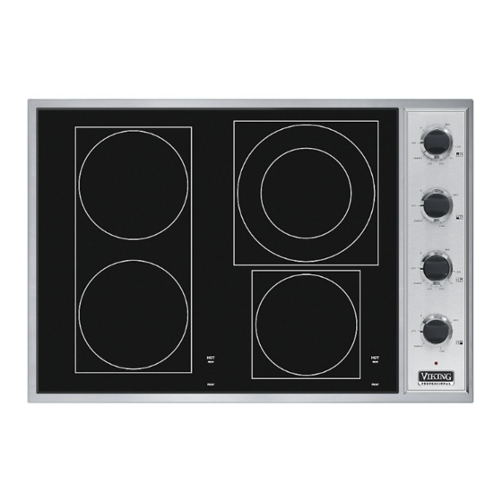
IMPORTANT: PLEASE READ AND FOLLOW SPECIFICATIONS - VECU ELECTRIC COOKTOP •Before beginning, please read these instructions completely and carefully. Description VECU106 30” W. VECU166 36” W. •Do not remove permanently affixed labels, warnings, or plates from the product. This may void the warranty. Cutout Width Minimum 28 3/4”... -
Page 3: Electrical Requirements
ELECTRICAL REQUIREMENTS PROXIMITY TO SIDE CABINET INSTALLATION Check your local codes regarding this unit. This cooktop is supplied with a 3-wire, A.C. 208/120 volt or 120/240 volt, 60 HZ electrical system. A white (neutral) is not needed for this unit. See next section for grounding instructions. It should 1. - Page 4 WOOD/COMPOSITE OVERLAY INSTALLATION 30” W. VECU TOP The bottom of the hood should be 30” (76.2 cm) min. to 36” (91.4 cm) max. above the countertop. This would typically result in the bottom of the hood being 66” (167.6 cm) to 72” (182.9 cm) above the floor. Refer to the rangehood in- stallation instructions for further information.
- Page 5 36” W. VECU TOP INSTALLATION OF HOLD DOWN BRACKET - VECU MODELS Front Brackets After installating cooktop with two of the sheet metal Countertop Cooktop screws (Item 1), locate the sheet metal screw hole in the rear of the burner box. Screw hold down brackets (Item 2) using the third sheet metal screw (Item 3) to the 21”...
- Page 6 DIMENSIONS 36” W. DECU TOP DECU HEIGHT 4 1/2” 3 1/2” (11.4 cm) (8.9 cm) 21” (53.3 cm) 3 1/16” (7.7 cm) 30” W. DECU TOP 36 3/4” (93.3 cm) 21” (53.3 cm) 30 3/4” (78.1 cm) Indentification Label Location 36”...
- Page 7 45” W. DECU TOP INSTALLATION OF HOLD DOWN BRACKET - DECU MODELS Top of cooktop Two (2) hold brackets will be provided with your unit. After cooktop has been installed into the countertop, locate the bracket in the slots as needed (Figure 1). Place a bracket 21”...
-
Page 8: Performance Checklist
PERFORMANCE CHECKLIST A qualified installer should carry out the following checks: 1. Check top surface elements - glow red when turned on. 2. Check hot surface indicator lights - glow red when corresponding element is hot. Any adjustments necessary that are a result of the installer not following instructions will be the responsibility of the in- staller, dealer of the end user of this product.