
Related Manuals for Scotsman AC Series


Summary of Contents for Scotsman AC Series
- Page 1 AC SERIES CUBERS TECHNICAL SERVICE TRAINING Welcome to another Scotsman technical service presentation. This one will cover the electronic units of new AC “..6” Series Ice Cube Machines. Models are AC 106, AC 126, AC 176, AC 206 and AC 226.
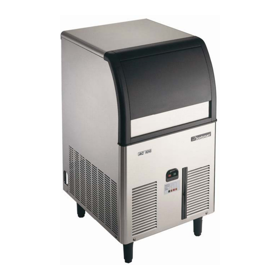
- Page 2 NEW AC SERIES AC 106 A/W Max. Ice Production = 50 kg/24h* Max. Storage Bin Capacity = 23 Kg * 10/10°C= Air & Water Inlet Temperature...
- Page 3 NEW AC SERIES AC 126 A/W Max. Ice Production = 71 Kg/24h* Max. Storage Bin Capacity = 39 Kg * 10/10°C= Air & Water Inlet Temperature...
- Page 4 NEW AC SERIES AC 176 A/W Max. Ice Production = 85 Kg/24h* Max. Storage Bin Capacity = 48 Kg * 10/10°C= Air & Water Inlet Temperature...
- Page 5 NEW AC SERIES AC 206 A/W Max. Ice Production = 137 Kg/24h* Max. Storage Bin Capacity = 50 Kg * 10/10°C= Air & Water Inlet Temperature...
- Page 6 NEW AC SERIES AC 226 A/W Max. Ice Production = 150 Kg/24h* Max. Storage Bin Capacity = 70 Kg * 10/10°C= Air & Water Inlet Temperature...
- Page 7 NEW AC SERIES TOPICS On the next slides are shown the following steps by steps procedures: • UNPACKING • INSTALLATION • START UP AND OPERATIONAL CHECKS • OPERATING PRINCIPLES and COMPONENTS • MAINTENANCE • SERVICE ANALYSIS...
- Page 8 NEW AC SERIES UNPACKING...
- Page 9 NEW AC SERIES UNPACKING The machines are supplied in a carton box secured by two plastic strips to a wooden base. Check first the outside conditions of carton box and wooden base then cut the two plastic strips, remove the tape...
- Page 10 NEW AC SERIES UNPACKING Visually inspect the exterior of the machine then open the bin door and remove from the inside the: • water supply inlet tube • water outlet tube • leg kit • sanitizing bag...
- Page 11 NEW AC SERIES UNPACKING Remove the adhesive tapes securing the curtain and the spray platen to the front of the water sump.
-
Page 12: Installation
NEW AC SERIES INSTALLATION... - Page 13 NEW AC SERIES INSTALLATION Check the data plate of the machine located on the rear panel for correct voltage as well as for the proper wiring/fuse size. Remember that all machines require a solid earth wire.
- Page 14 NEW AC SERIES INSTALLATION Check for the correct water and ambient conditions that should be: • Min. ambient temperature 10ºC (50F) • Max. ambient temperature 40ºC (100F) • Min. water temperature 5ºC (40F) • Max. water temperature 35ºC (90F) • Min. water pressure 1 bar (14 PSI) •...
- Page 15 NEW AC SERIES INSTALLATION Adequate space must Min. space 15 cm be left for proper water and electrical connections on the rear side of the machine. A minimum clearance of 15 cm on both sides for best routing air.
- Page 16 NEW AC SERIES INSTALLATION - AIR CIRCULATION Fan Motor COLD AIR Condenser HOT AIR Compressor Control box...
- Page 17 NEW AC SERIES INSTALLATION Installation under counter with no space of both sides are allowed but daily ice capacity can drop down to a maximum of 20%.
- Page 18 NEW AC SERIES INSTALLATION Level the unit on both directions front to rear and…...
- Page 19 NEW AC SERIES INSTALLATION ……. right to left side using the adjustable legs.
-
Page 20: Installation - Electrical
NEW AC SERIES INSTALLATION - ELECTRICAL Install, on the cable supply with the machine, an adequate electrical plug according to the local standards and regulations. Maximum voltage variation should be ±10%. Machine must be individually fuse protected. - Page 21 NEW AC SERIES INSTALLATION – WATER IN Connect the water inlet 3/4” male threat of the water inlet solenoid valve to the water supply line by means of the rubber hose provided with machine. Install on water supply line closed to the machine...
- Page 22 NEW AC SERIES INSTALLATION – WATER DRAIN Connect the 20 mm O.D. fitting of the water drain with the flexible hose supply with the machine securing it by proper clamp. As water will be mainly drained under pressure (by water pump) it is not necessary to have a vented drain.
-
Page 23: Typical Installation
NEW AC SERIES TYPICAL INSTALLATION AIR COOLED VERSION HAND DISCONNECT SWITCH WATER VALVE WATER FILTER POWER WATER INLET WATER DRAIN... - Page 24 NEW AC SERIES INSTALLATION AC 126 – AC 176 – AC 206 - AC 226 On the water cooled version there are two separate 3/4” male thread water inlet fittings…..
- Page 25 NEW AC SERIES INSTALLATION AC 126 – AC 176 – AC 206 - AC 226 …...one connected directly to the water regulating valve that must be connect to the water supply line by means a second rubber hose provided with...
- Page 26 NEW AC SERIES INSTALLATION AC 126 – AC 176 – AC 206 - AC 226 …..a second separate drain hose must be connected to the outlet 3/4” male fitting located beside the water regulating valve.
- Page 27 NEW AC SERIES INSTALLATION AC 106 ONLY On the water cooled version of the AC 106 only there are two water inlet solenoid valve with two separated outlet fittings...
- Page 28 NEW AC SERIES TYPICAL INSTALLATION WATER COOLED VERSION HAND DISCONNECT SWITCH WATER VALVE WATER FILTER WATER INLETS POWER WATER DRAINS...
- Page 29 NEW AC SERIES START UP AND OPERATIONAL CHECKS...
- Page 30 NEW AC SERIES START UP AND OPERATIONAL CHECKS Open the water tap/valve and Switch ON the power on the electrical supply line.
- Page 31 NEW AC SERIES START UP AND OPERATIONAL CHECKS Push the Green Push Button Switch to Start Up the machine...
- Page 32 NEW AC SERIES START UP AND OPERATIONAL CHECKS The Ice Machine will start up automatically through the 5 minutes “Water Filling Phase”. AC 126- AC 176 WATER DRAIN VALVE NOT USED ON AC106...
- Page 33 NEW AC SERIES START UP AND OPERATIONAL CHECKS AC 206- AC 226...
- Page 34 NEW AC SERIES START UP AND OPERATIONAL CHECKS The components energized during this period are: • PC Board...
- Page 35 NEW AC SERIES START UP AND OPERATIONAL CHECKS • Water Inlet Solenoid Valve...
- Page 36 NEW AC SERIES START UP AND OPERATIONAL CHECKS • Water drain valve (not used on AC106)
- Page 37 NEW AC SERIES START UP AND OPERATIONAL CHECKS • Hot Gas Solenoid Valve...
- Page 38 NEW AC SERIES START UP AND OPERATIONAL CHECKS ….flows into the small During the first 5’ the water orifice of the “Flow Control” goes through the Water Inlet located on the outlet port of Valve then… the same.
- Page 39 NEW AC SERIES START UP AND OPERATIONAL CHECKS ..where it flows onto the Following the plastic inlet plastic evaporator platen hose the incoming water dribbling down through the arrive on the upper side of holes located on the corners.
- Page 40 NEW AC SERIES START UP AND OPERATIONAL CHECKS Dribbled water is collected down into the water sump where is located the overflow that assures the proper water level and quantity for the next freezing cycle.
- Page 41 NEW AC SERIES START UP AND OPERATIONAL CHECKS After the first 5’ of water filling phase the machine start up automatically on freezing cycle with the following electrical components in operation: • Compressor...
- Page 42 NEW AC SERIES START UP AND OPERATIONAL CHECKS • Water Pump...
- Page 43 NEW AC SERIES START UP AND OPERATIONAL CHECKS • Fan Motor (on air cooled version only)
- Page 44 NEW AC SERIES START UP AND OPERATIONAL CHECKS The operation of the fan motor is controlled by a condenser temperature sensor located within the fins of condenser that transmit a signal to the PC Board to activate in ON-OFF mode the fan motor...
- Page 45 NEW AC SERIES START UP AND OPERATIONAL CHECKS On PC Board the LED energized are: • Power PUSH FREEZING CYCLE TOO HI COND TEMP TOO HI EVAP TEMP BIN FULL POWER...
- Page 46 NEW AC SERIES START UP AND OPERATIONAL CHECKS On PC Board the LED energized are: • Power • Freezing PUSH FREEZING CYCLE TOO HI COND TEMP TOO HI EVAP TEMP BIN FULL POWER...
- Page 47 NEW AC SERIES START UP AND OPERATIONAL CHECKS Water is circulating by the water pump into the inverted tin plated copper molds of the evaporator….
- Page 48 NEW AC SERIES START UP AND OPERATIONAL CHECKS ….while the refrigerant is flowing into the serpentine welded on the upper side of the tin plated copper molds.
- Page 49 NEW AC SERIES START UP AND OPERATIONAL CHECKS After approximately 5 minutes since the start up of the freezing cycle, the 0ºC temperature of the evaporator serpentine drops down to 0ºC….
- Page 50 NEW AC SERIES START UP AND OPERATIONAL CHECKS ….with the blinking of the small RED LED located in the center of PC Board.
- Page 51 NEW AC SERIES START UP AND OPERATIONAL CHECKS After approximately 10 minutes from the start up of the freezing cycle, the temperature of -15ºC the evaporator serpentine drops down to - 15ºC….
- Page 52 NEW AC SERIES START UP AND OPERATIONAL CHECKS ….with the light ON steady of the small RED LED located in the center of PC Board.
- Page 53 NEW AC SERIES START UP AND OPERATIONAL CHECKS The machine remains in the freezing cycle till its completion for an additional time according to the set up of the first four DIP SWITCH of the PC Board.
- Page 54 NEW AC SERIES START UP AND OPERATIONAL CHECKS Once completed the freezing cycle the machine enters into the defrost or harvest cycle with the following electrical components in operation: • Compressor...
- Page 55 NEW AC SERIES START UP AND OPERATIONAL CHECKS • Water Inlet Solenoid valve...
- Page 56 NEW AC SERIES START UP AND OPERATIONAL CHECKS • Water Drain/Purge Solenoid Valve (Not Used on AC 106)
- Page 57 NEW AC SERIES START UP AND OPERATIONAL CHECKS • Hot Gas Valve...
- Page 58 NEW AC SERIES START UP AND OPERATIONAL CHECKS According to the setting of the DIP SWITCH no 9 the Water Pump can remain in operation to discharge the water not used on the previous freezing cycle during the first..
- Page 59 NEW AC SERIES START UP AND OPERATIONAL CHECKS AC 126-176 ….15” of the OFF = 15 seconds harvest cycle, when the DIP AC 206-226 SWITCH is in OFF position, or ON = 30 seconds 30” when in ON position.
- Page 60 NEW AC SERIES START UP AND OPERATIONAL CHECKS The length of SWITCH 5 AND 6 the defrost or harvest cycle is controlled by the PC Board according to the setting of the DIP SWITCH 5 and 6 and it is...
- Page 61 NEW AC SERIES START UP AND OPERATIONAL CHECKS LENGTH OF HARVEST CYCLE ACCORDING TO THE TIME …..the time that the TO DROP THE EVAP. TEMPERATURE FROM 0ºC TO -13ºC machine takes to drop LENGTH PROGRAMS HARVEST CYCLE the evaporating 180”...
- Page 62 NEW AC SERIES START UP AND OPERATIONAL CHECKS It’s possible to extend the length of the defrost cycle by means of the DIP SWITCH 7 and 8 as per below chart. DIP SWITCH ADDITIONAL DEFROST TIME 30" 60" 90" WATER PUMP OFF...
- Page 63 NEW AC SERIES START UP AND OPERATIONAL CHECKS During the defrost or harvest cycle the combined action of refrigerant in Hot Gas state and incoming Water are going to partially melt the ice cubes in contact with the tin plated copper...
- Page 64 NEW AC SERIES START UP AND OPERATIONAL CHECKS With some ice cubes between the I/R Optical Ice Level Sensor during the defrost cycle it is possible to test its operation.
- Page 65 NEW AC SERIES START UP AND OPERATIONAL CHECKS The Bin Full YELLOW LED starts to blink slow. PUSH FREEZING CYCLE TOO HI COND TEMP TOO HI EVAP TEMP BIN FULL POWER...
- Page 66 NEW AC SERIES START UP AND OPERATIONAL CHECKS Till the end of the next freezing cycle in order to release full ice cubes at every time; after that the machine will stop at bin full condition with the yellow LED steady ON...
- Page 67 NEW AC SERIES START UP AND OPERATIONAL CHECKS As soon as the ice is removed between transmitter and received the infrared beam is resumed immediately with fast a blinking of the Yellow LED, then the machine restart with 45” of recharging...
-
Page 68: Operating Principles
NEW AC SERIES OPERATING PRINCIPLES COMPONENTS... - Page 69 NEW AC SERIES OPERATING PRINCIPLES - FREEZE Evaporator Compressor Air cooled valve condenser...
- Page 70 NEW AC SERIES OPERATING PRINCIPLES - HARVEST Evaporator Compressor Air cooled valve condenser...
- Page 71 NEW AC SERIES WATER SYSTEM – FREEZING CYCLE AC 106...
- Page 72 NEW AC SERIES WATER SYSTEM – HARVEST CYCLE AC 106...
- Page 73 NEW AC SERIES WATER SYSTEM – FREEZING CYCLE AC 126-176...
- Page 74 NEW AC SERIES WATER SYSTEM – HARVEST CYCLE FIRST PORTION 15” AC 126-176...
- Page 75 NEW AC SERIES WATER SYSTEM – HARVEST CYCLE SECOND PORTION AC 126-176...
- Page 76 NEW AC SERIES WATER SYSTEM – FREEZING CYCLE AC 206-226...
- Page 77 NEW AC SERIES WATER SYSTEM – HARVEST CYCLE FIRST PORTION 30” AC 206-226...
- Page 78 NEW AC SERIES WATER SYSTEM – HARVEST CYCLE SECOND PORTION AC 206-226...
- Page 79 NEW AC SERIES OPERATING PRINCIPLES – MASTER SWITCH All AC units are equipped with a Green Lighted Master Push Switch located in the front panel. By pushing it, it possible to Switch ON and OFF the machine.
- Page 80 NEW AC SERIES OPERATING PRINCIPLES – ALARM/RESET SWITCH Beside the Green Master Switch is located a Red Alarm Light & Reset Switch that operates in conjunction with the condenser sensor…...
- Page 81 NEW AC SERIES OPERATING PRINCIPLES – ALARM & REMIND BOARD …has the main function to transmit, to the External Red Alarm Light, the proper signal according to the need of the machine.
- Page 82 NEW AC SERIES OPERATING PRINCIPLES – ALARM& REMIND BOARD...
- Page 83 NEW AC SERIES OPERATING PRINCIPLES – TRIP OFF Whenever condensing temperature rises up to 70ºC, the condenser sensor installed >70ºC inside the condenser fins ….
- Page 84 NEW AC SERIES OPERATING PRINCIPLES – TRIP OFF …send the signal to the Board to Switch Off immediately the operation of the machine.
- Page 85 NEW AC SERIES OPERATING PRINCIPLES – FILTER CLEAN In case the Red Light is blinking FAST with the machine in operation it means….
- Page 86 NEW AC SERIES OPERATING PRINCIPLES – FILTER CLEAN …. that the condensing temperature is more then 60°C but less then 70° and the condenser air filter needs to be cleaned.
- Page 87 NEW AC SERIES OPERATING PRINCIPLES – WATER SYSTEM CLEAN In case the Red Light is blinking SLOW with the machine in operation it means….
-
Page 88: Maintenance
NEW AC SERIES OPERATING PRINCIPLES – WATER SYSTEM CLEAN AC 46-56-86 AC 46-56-86 …. to proceed with the MAINTENANCE MAINTENANCE cleaning of the TOOLS REQUIRED • Medium Phillips Screwdriver water system of • Medium Flat Screwdriver the machine as • Pair of safety gloves detailed on the •... - Page 89 NEW AC SERIES OPERATING PRINCIPLES – WATER SYSTEM CLEAN Once water system is cleaned it’s necessary to restart the count down timer, of the Remind PC Board, by pushing and holding for more then 20” the Red Re-Set button.
- Page 90 JUMP OUT – EC SERIES START UP DELAY RESET BUTTON JUMP IN - AC SERIES JUMP OUT - OFF 0°C- BLINKING JUMP IN - 60’ -13°C- STEADY WATER PUMP RELAY EC SERIES REMIND CLEANING TEST JUMP OUT - 12 MONTHS...
- Page 91 NEW AC SERIES OPERATING PRINCIPLES – DIP SWITCHES SWITCH 9 SWITCH 7 AND 8 SWITCH 5 AND 6 OPERATING TIME EXTENTION TIME OF LENGTH OF THE OF WATER PUMP HARVEST CYCLE BY 0”, 30”, HARVEST CYCLE DURING HARVEST 60” OR WATER PUMP OFF ACCORDING TO THE OFF = 15”...
- Page 92 JUMP IN - 0 MIN. AC/EC MODELS JUMP IN - 0 MIN. AC/EC MODELS JUMP OUT - 60 MIN. JUMP IN – AC SERIES JUMP OUT - 60 MIN. JUMP IN – AC SERIES JUMP OUT - EC SERIES JUMP OUT - EC SERIES...
- Page 93 NEW AC SERIES OPERATING PRINCIPLES – PC BOARD Time T From start up of freezing cycle till the blinking of 0°C Red...
- Page 94 NEW AC SERIES OPERATING PRINCIPLES – PC BOARD Time T From blinking of Red LED till the light ON steady of -15°C Red LED...
- Page 95 NEW AC SERIES OPERATING PRINCIPLES – PC BOARD LENGTH OF TIMED PORTION OF FREEZING Time T CYCLE – FIRST 4 SWITCHES Added time controlled by the PC Board 25’ 23’ 21’ according to the setting 17’ 19’ of the DIP SWITCH 15’...
- Page 96 NEW AC SERIES OPERATING PRINCIPLES – PC BOARD Time T Harvest Time T LENGTH OF HARVEST CYCLE ACCORDING TO THE TIME TO DROP THE EVAP. TEMPERATURE FROM 0ºC TO -13ºC controlled by the PC Board and it is inversely LENGTH...
- Page 97 NEW AC SERIES OPERATING PRINCIPLES – PC BOARD It’s possible to extend the length of the harvest cycle (T by means of the DIP SWITCH 7 and 8 as per below chart. DIP SWITCH ADDITIONAL DEFROST TIME 30" 60" 90"...
- Page 98 NEW AC SERIES OPERATING PRINCIPLES – PC BOARD 0°C -15°C Time Time T Time T Freezing = T Defrost/Harvest = T...
-
Page 99: Alarm Led
NEW AC SERIES OPERATING PRINCIPLES – PC BOARD ALARMS TOO HI COND. TEMPERATURE Whenever the condensing temperature rise up to 70ºC (air cooled FREEZING CYCLE version) or 60ºC TOO HI COND TEMP TOO HI EVAP TEMP (water cooled version) the PC Board will... - Page 100 NEW AC SERIES OPERATING PRINCIPLES – PC BOARD ALARMS TOO HI EVAPORATOR TEMPERATURE In case the evaporating temperature remains higher then 0ºC after 15 FREEZING CYCLE minutes from the TOO HI COND TEMP beginning of the freezing TOO HI EVAP TEMP...
- Page 101 NEW AC SERIES OPERATING PRINCIPLES – PC BOARD ALARMS CONDENSER SENSOR OUT OF ORDER In case both the Red and Yellow LED are light ON FREEZING CYCLE steady TOO HI COND TEMP condenser TOO HI EVAP TEMP sensor is out of...
- Page 102 NEW AC SERIES OPERATING PRINCIPLES – PC BOARD ALARMS EVAPORATOR SENSOR OUT OF ORDER In case both the Red and Yellow LED are blinking FREEZING CYCLE the evaporator sensor is out of TOO HI COND TEMP TOO HI EVAP TEMP...
- Page 103 NEW AC SERIES OPERATING PRINCIPLES – PC BOARD ALARMS ICE LEVEL CONTROL OUT OF ORDER Whenever red and FREEZING CYCLE yellow LEDs blinks TOO HI COND TEMP TOO HI EVAP TEMP alternatively ice level BIN FULL POWER control is our of order...
- Page 104 NEW AC SERIES OPERATING PRINCIPLES – PC BOARD ALARMS ICE LEVEL CONTROL CALIBRATION Three LED flash : ice level control – FREEZING CYCLE TOO HI COND TEMP TOO HI EVAP TEMP PCB balance / BIN FULL calibration done POWER...
- Page 105 START UP DELAY JUMP IN - 0 MIN. AC/EC MODELS JUMP IN - 0 MIN. AC/EC MODELS JUMP IN – AC SERIES JUMP OUT - 60 MIN. JUMP IN – AC SERIES JUMP OUT - 60 MIN. JUMP OUT - EC SERIES...
- Page 106 JUMP IN - 0 MIN. AC/EC MODELS JUMP IN - 0 MIN. AC/EC MODELS JUMP OUT - 60 MIN. JUMP IN – AC SERIES JUMP IN – AC SERIES JUMP OUT - 60 MIN. JUMP OUT - EC SERIES JUMP OUT - EC SERIES...
- Page 107 NEW AC SERIES COMPONENTS - REFRIGERANT SYSTEM The components of the refrigerant system of the Models AC 106 up to AC 226 are composed by: • COMPRESSOR...
- Page 108 NEW AC SERIES COMPONENTS - REFRIGERANT SYSTEM • CONDENSER...
- Page 109 NEW AC SERIES COMPONENTS - REFRIGERANT SYSTEM • EVAPORATOR...
-
Page 110: Capillary Tube
NEW AC SERIES COMPONENTS - REFRIGERANT SYSTEM • SUCTION LINE AND CAPILLARY TUBE... - Page 111 NEW AC SERIES COMPONENTS - REFRIGERANT SYSTEM • DRIER...
- Page 112 NEW AC SERIES COMPONENTS - REFRIGERANT SYSTEM • HOT GAS VALVE...
- Page 113 NEW AC SERIES COMPONENTS - WATER SYSTEM The components of the water system of the Models AC 106 up to AC 226 are composed by: • WATER INLET VALVE...
- Page 114 NEW AC SERIES COMPONENTS - WATER SYSTEM • WATER SUMP AC 106-126-176...
- Page 115 NEW AC SERIES COMPONENTS - WATER SYSTEM • WATER SUMP AC 206-226...
- Page 116 NEW AC SERIES COMPONENTS - WATER SYSTEM • WATER PUMP...
- Page 117 NEW AC SERIES COMPONENTS - WATER SYSTEM • SPRAY PLATEN AC 106 ONLY...
- Page 118 NEW AC SERIES COMPONENTS - WATER SYSTEM • SPRAY PLATEN AC 126-176...
- Page 119 NEW AC SERIES COMPONENTS - WATER SYSTEM • SPRAY BAR AC 206-226...
- Page 120 NEW AC SERIES COMPONENTS - WATER SYSTEM • OVERFLOW AC 106-126-176...
- Page 121 NEW AC SERIES COMPONENTS - WATER SYSTEM • OVERFLOW AC 206-226...
-
Page 122: Water Drain Valve
NEW AC SERIES COMPONENTS - WATER SYSTEM • WATER DRAIN VALVE (NOT used on AC 106) - Page 123 NEW AC SERIES COMPONENTS - ELECTRICAL CONTROLS The components of the Electric System of the Models AC 106 up to AC 226 are composed by: • MASTER SWICH...
- Page 124 NEW AC SERIES COMPONENTS - ELECTRICAL CONTROLS • ALARM-RESET SWITCH...
- Page 125 NEW AC SERIES COMPONENTS - ELECTRICAL CONTROLS • PC BOARD...
- Page 126 NEW AC SERIES COMPONENTS - ELECTRICAL CONTROLS • EVAPORATOR SENSOR...
- Page 127 NEW AC SERIES COMPONENTS - ELECTRICAL CONTROLS • CONDENSER SENSOR...
- Page 128 NEW AC SERIES COMPONENTS - ELECTRICAL CONTROLS • OPTICAL ICE LEVEL CONTROL...
- Page 129 NEW AC SERIES COMPONENTS - ELECTRICAL CONTROLS • CONDENSER SENSOR...
- Page 130 END FIRST HALF...
Need help?
Do you have a question about the AC Series and is the answer not in the manual?
Questions and answers