Advertisement
Quick Links
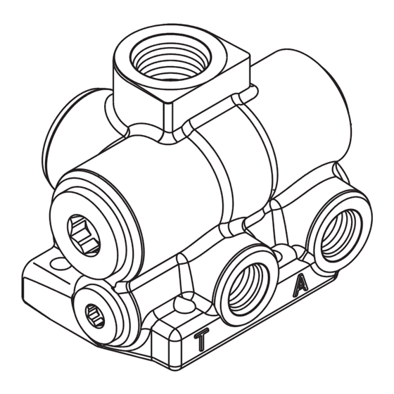
PRODUCT EXPLANATION
The accumulator charging valve is designed for installation
in an open center hydraulic system between the pump and
the downstream secondary hydraulic devices.
The accumulator charging valve supplies oil on demand to
the accumulator from the open center circuit. Accumulator
charging is accomplished at a preset rate (GPM) and is
relatively constant within the preset pressure limits.
The flow to the downstream secondary hydraulic
devices will be reduced fractionally for a short time when
the accumulator is charging. This does not noticeably affect
operation of these components. Full system pressure is
available to the downstream secondary hydraulic devices
at all times provided oil delivery and pressure from the
pump is not impeded.
IMPORTANT INFORMATION
A
Due to allowable operating temperature of accumulator
charging valve avoid contact or burn injury may occur.
B
Be sure system energy is relieved from accumulator
charging valve before removing from machine. See
machine operating instructions for procedures to relieve
system energy.
This document is intended to provide general information about MICO Products. MICO, Inc. has attempted to present accurate information about MICO Products
in its catalogs, brochures, and other printed materials. MICO, Inc. is not responsible for errors, inaccuracies, or inconsistencies that may exist in any catalog,
brochure, or other printed materials or any damages arising from or related to reliance on information in them. Materials and specifications for MICO Products set
forth in catalogs, brochures, and other printed materials are subject to change without notice or obligation. Refer to www.mico.com for the most recent versions of
our literature. If you have any questions concerning MICO Products, please contact MICO, Inc. All MICO Products and service are sold and provided subject to the
MICO Warranty at www.mico.com in effect on the date of sale or supply.
MICO is a trademark and registered trademark of MICO, Inc. MICO is registered in the U.S. Patent and Trademark Office as well as in Australia, Canada, Indonesia, Japan, Peoples Republic of China, South Korea, and the European Community.
Form No. 81-463-003
ACV-SMO
Revised 2017-10-24
SINGLE ACCUMULATOR
CHARGING VALVE
Product Explanation,
Operating Information
and Service Instructions
This accumulator charging valve does not limit pressure
in the accumulator that is from system load downstream
of the flow through port. Over pressure protection is to
be located between the pump and accumulator charging
valve.
OPERATING INFORMATION
End user must provide proper maintenance of valve,
should it become inoperable, by replacing the valve or
servicing it with the proper repair kit. See TABLES 1, 2,
and 3 on pages 3, 5, and 7 for the proper repair kit number.
Observe Service Instruction procedures on following
pages. See Warnings A, B, and C below.
C
Do not exceed the high limit pressure setting indicated in
TABLE 1, 2, and 3 or system damage or failure may occur.
MICO, Inc.
1911 Lee Boulevard / North Mankato, MN U.S.A. 56003-2507
Tel: +1 507 625 6426
Fax: +1 507 625 3212
www.mico.com
Advertisement

Related Manuals for WABCO MICO ACV-SMO


Summary of Contents for WABCO MICO ACV-SMO
- Page 1 SINGLE ACCUMULATOR CHARGING VALVE Product Explanation, Operating Information and Service Instructions ACV-SMO PRODUCT EXPLANATION The accumulator charging valve is designed for installation This accumulator charging valve does not limit pressure in an open center hydraulic system between the pump and in the accumulator that is from system load downstream the downstream secondary hydraulic devices.
-
Page 2: Valve Adjustment
4. Install spring (3) and rod (4) into housing (7). NOTE 5. Install new o-ring (2) on plug (1). Install plug (1) into housing Locate the model number on the accumulator charging valve and (7) and torque 122.0-135.6 N∙m (90-100 lb∙ft). compare it to the model number in TABLE 1. - Page 3 ● Items included in Repair Kit Figure 1b Figure 1a FIGURE 1 TABLE 1 (Specifications) Nominal Nominal Model Repair Kit High Limit (cut out) Low Limit (cut in) Number Number (PSI) (PSI) 06-463-006 06-400-099 103.4 ± 3.5 (1500 ± 50) 82.7 ±...
- Page 4 4. Install spring (3) and rod (4) into housing (7). NOTE 5. Install new o-ring (2) on plug (1). Install plug (1) into housing Locate the model number on the accumulator charging valve and (7) and torque 122.0-135.6 N∙m (90-100 lb∙ft). compare it to the model number in TABLE 2.
- Page 5 ● Items included in Repair Kit Included only in Repair Kit 06-400-323 Figure 2b Figure 2a FIGURE 2 NOTE Repair kit includes a plastic poppet which is not used in these models. TABLE 2 (Specifications) Nominal Nominal Model Repair Kit High Limit (cut out) Low Limit (cut in) Number...
- Page 6 Assembly NOTE (Refer to Figure 3) Locate the model number on the accumulator charging valve and WASH ALL PARTS WITH CLEAN SOLVENT AND DRY. LUBRICATE compare it to the model number in TABLE 3. Be sure you have ALL RUBBER PARTS WITH CLEAN SYSTEM FLUID PRIOR TO the proper service instructions.
- Page 7 ● Items included in Repair Kit Figure 3b Figure 3a FIGURE 3 NOTE Repair kit includes a plastic poppet and plastic pin which are not used in this model. TABLE 3 (Specifications) Nominal Nominal Model Repair Kit High Limit (cut out) Low Limit (cut in) Number Number...
-
Page 8: Service Diagnosis
SERVICE CHECKS FOR HYDRAULIC SYSTEMS ACCUMULATOR CHARGING CYCLE ACCUMULATOR CHARGING TIME TOO VERY RAPID CYCLING OF CHARGING REPEATS FREQUENTLY WHEN ACCU- LONG VALVE MULATOR IS NOT NORMALLY BEING 1. No oil or low oil level in tank 1. Incorrect setting of accumulator DISCHARGED IN SERVICE 1.