Advertisement
Quick Links
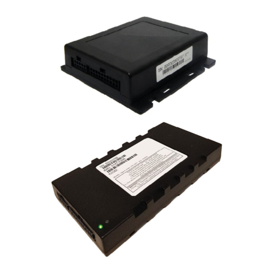
Commercial Vehicle Productivity and Security
The 65xx family of beacons includes the following models:
•
6550 – 3G with external antenna
•
6551 – 3G with internal antenna
•
6581 – 4G (LTE) with internal antenna
These versatile GPS tracking beacons are designed for fleet management needs in all
commercial vehicles.
Combined with our commercial mobile monitoring portal, subscribers can manage and
view the location of any or all vehicles in a fleet, run a variety of valuable reports, and
manage vehicle maintenance alerts.
Kit Contents
• GPS Beacon device with SIM
• Combined GPS/Cell Network antenna (if
required)
• Wiring harness
Antenna Configuration
The 65xx beacons have a combined GPS/cell
network antenna module. The 6550 model uses an
external antenna attached with FAKRA connectors,
while the 6551 and 6581 are equipped with an
internal antenna housed within the beacon.
For either configuration, the antenna must be
positioned in the vehicle so that it has a clear
signal path to as much of the sky as possible,
without metal obstruction. For internal antennas,
the beacon itself must be positioned properly for
good signal reception.
External Antenna Installation (6550 only)
The following antenna models are supported:
Standard Antenna
•
Part Number: 6xx0-ANT-STD
•
Black plastic housing; approx. 2.5 in (64 mm) diameter;
0.4 in (10 mm) depth
•
Mounted with peel-and-stick adhesive patch
rev 2023.12.20
Page
1
of 6
Vecima 65xx Beacon Family
Tools and Supplies Required
• Wire cutters, wire strippers
• Voltmeter (multimeter)
• Soldering iron, solder
• Electrical tape
Weatherproof Drill-through Antenna
•
Part Number: 6xx0-ANT-WPA-DT
•
Black plastic housing with rubber weather-seal;
approx. 2.5 in (64 mm) diameter; 0.7 in (18 mm) depth
(excluding screw post)
•
Screw post mount for drill-through applications
installation guide
• Plastic cable ties
• Screw drivers, mounting screws
• Wrenches, sockets
© 2023 Vecima Networks Inc. All rights reserved.
www.vecima.com
Advertisement

Related Manuals for Vecima 65 Series

Summary of Contents for Vecima 65 Series
- Page 1 2.5 in (64 mm) diameter; 0.7 in (18 mm) depth (excluding screw post) • Mounted with peel-and-stick adhesive patch • Screw post mount for drill-through applications rev 2023.12.20 www.vecima.com Page of 6 © 2023 Vecima Networks Inc. All rights reserved.
- Page 2 These models are ideally located under the dashboard, and the same guidelines for installing an external antenna (described above) are applicable. • Visibility of the indicator LEDs will be useful for testing and troubleshooting. rev 2023.12.20 www.vecima.com © 2023 Vecima Networks Inc. All rights reserved. Page of 6...
-
Page 3: Important Notices
Failure to install the ignition sense correctly will result in erroneous data being reported from the beacon. This may result in false or incorrect reporting of vehicle starts, stops, ignition on and off. rev 2023.12.20 www.vecima.com © 2023 Vecima Networks Inc. All rights reserved. Page of 6... - Page 4 When using auxiliary inputs to measure the state of vehicle circuits, it is recommended that you use a relay to control the input signal to the device. rev 2023.12.20 www.vecima.com © 2023 Vecima Networks Inc. All rights reserved. Page of 6...
-
Page 5: Led Indicators
(1=hardware, 2=modem, 3=GPS, 4=end-to-end service) and the second digit indicates a more specific error described in the table below. Note that if multiple error conditions exist, the LED will cycle through all current error conditions. rev 2023.12.20 www.vecima.com © 2023 Vecima Networks Inc. All rights reserved. Page of 6... - Page 6 The 65xx beacons are not waterproof or sealed devices. Care must be taken to ensure the device is kept away from water or any other liquids, as well as excessive dust. • The 65xx beacons may be incompatible with certain models of vehicles. For more information please contact Vecima Support. rev 2023.12.20 www.vecima.com ©...