Advertisement
Quick Links
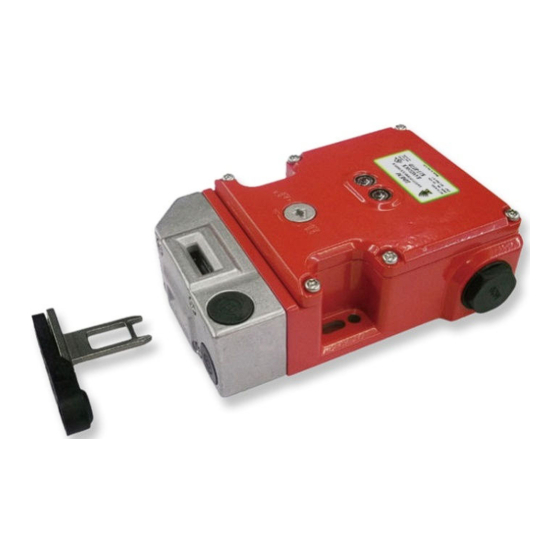
Application:
The KLTM-RFID and KLT-SS-RFID Safety Interlock switches are designed to fit to the leading edge of machine guard doors to provide robust guard locking and provide a double
tamper resistant interlock mechanism.
They are designed to provide robust position interlock detection for moving guards and will remain locked until the solenoid voltage is applied to the switch. They will hold closed up to
2000N on hinged guards. They can be used in conjunction with delay timers to provide the solenoid energisation only after a pre-determined the time has run down.
Operation:
The switch is rigidly mounted to the fixed frame of the guard or machine. The actuator is fitted to the moving part (frame) of the guard and is aligned to the switch entry aperture. The
mechanical tongue actuator profile is designed to match a cam mechanism within the switch head and provides a positively operated not easily defeatable mechanical interlock. There
is also an RFID coded actuator which aligns with a programmed receiver inside the switch housing during closing of the guard. Only when both actuators are correctly aligned and the
RFID coding is verified correctly can the safety contacts close and allow the machine start circuit to be enabled. When the solenoid is energised the safety contacts are positively
opened and the machine circuit is broken.
Installation:
1.
Installation of all IDEM interlock switches must be in accordance with a risk assessment for the individual application.
Installation must only be carried out by competent personnel and in accordance with these instructions.
2.
M5 (or appropriate) mounting bolts must be used to fix the switch and actuator mounting plates. The tightening torque to ensure reliable fixing is 4.0 Nm.
Tightening torque for the lid screws and cable glands must be 1.5 Nm to ensure the IP seal. The actuator entry position (Front or End) can be selected by using the internal
slide switch inside the switch cover (See Fig.2 on page 2).
3.
Always fit a mechanical stop to the guard to prevent damage to the front of the switch.
Always ensure correct alignment of actuator and handle with front apertures of the switch and guide.
Use alignment guides to ensure that the actuator enters the switch without interfering with the sides of the aperture.
Ensure access to at least one of the manual release points.
Always fit the aperture plug to the unused entry aperture to prevent debris entering the switch mechanism.
4.
The RFID code is factory set. For instances where replacement of the RFID actuator is required please contact IDEM via e-mail: technical@idemsafety.com.
5.
The switch is supplied with removable conductor links fitted 41/42 and 31/32. If required by the control circuit these may be removed to offer independent monitoring of the
solenoid locking function or the actuator. Important: If conductor links are removed, circuits 11/31 and 21/41 must always be used.
6.
After installation check operation of all control circuits and the locking function.
For applications with a run down time after removing power, ensure that the correct timing allowance has been made before the solenoid is energised.
LED 1 (GREEN) will illuminate when the Gate is locked.
LED 2 (RED) will illuminate when power is applied to the solenoid.
Maintenance:
Every week: Check correct operation of all circuits and the Lock function. If the actuator shows
signs of bending or the switch head housing displays mechanical damage then remove and
replace.
IDEM will not accept responsibility for failure of the switch functions if the installation and
maintenance requirements shown in this sheet are not implemented.
These requirements form part of the product warranty.
Every 6 months: Isolate power and remove cover. Check screw terminal tightness and check for
signs of moisture ingress. Never attempt to repair any switch.
THESE INSTRUCTIONS FORM PART OF THE PRODUCT WARRANTY.
Tongue Switch with Guard Locking & RFID Coding
KLTM-RFID & KLT-SS-RFID Operating Instructions
Quick Connect (QC)
M23 12 way Male Plug
Switch Circuit
(Pin view from Switch)
1
0V
2
R+ 24V.dc
3
S+ 24V.dc
4
6
11/12
7
8
21/22
5
44
9
34
Earth
12
Advertisement

Related Manuals for Idem KLTM-RFID

Summary of Contents for Idem KLTM-RFID
- Page 1 KLTM-RFID & KLT-SS-RFID Operating Instructions Application: The KLTM-RFID and KLT-SS-RFID Safety Interlock switches are designed to fit to the leading edge of machine guard doors to provide robust guard locking and provide a double tamper resistant interlock mechanism. They are designed to provide robust position interlock detection for moving guards and will remain locked until the solenoid voltage is applied to the switch. They will hold closed up to 2000N on hinged guards.
- Page 2 Vibration IEC 68-2-6, 10-55Hz+1Hz, Excursion: 0.35mm, 1 octave/min IDEM SAFETY SWITCHES Ltd., 2 Ormside Close, Hindley Industrial Estate, Hindley Green, Wigan, WN2 4HR UK. Tel: +44 (0)1942 257070 Fax.: +44 (0)1942 257076 Doc: 102540 IDEM (USA) 4416 Technology Drive, Fremont, CA 94538 Tel:510-445-0751 Fax:1866-431-7064 email: sales@idemsafety.com...