Table of Contents
Advertisement
Quick Links
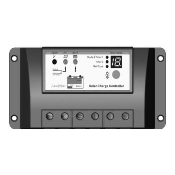
Solar Charge Controller 6830-122-C10/15/20
Solar Charge Controller
I I I I NSTRUCTION
NSTRUCTION
NSTRUCTION
NSTRUCTION
MAN
MAN
MAN
MANUAL
UAL
UAL
UAL
U-Tron (Beijing) Electroncis Co. Ltd.,
10 Langjiayuan, Chaoyang, Beijing
100022, China
http://www.u-tron.com
Solar Charge Controller 6830-122-C10/15/20
Contents
1 Important Safety Information .......................................1
2 General Information ......................................................2
2.1 Product Overview...................................................2
2.2 Product Features .....................................................3
3 Installation Instructions .................................................4
3.1 General Installation Notes .....................................4
3.2 Mounting.................................................................4
3.3 Wiring .....................................................................6
4 Operation......................................................................10
4.1 PWM Technology ................................................10
4.2 Battery Charging Information .............................10
4.3 LED Indicators .....................................................12
4.4 Setting Operation..................................................14
5.1 Protection ..............................................................18
5.2 Troubleshooting ..................................................19
5.3 Maintenance ......................................................21
6 Warranty.......................................................................22
7 Technical Specifications .............................................23
http://www.u-tron.com
Solar Charge Controller 6830-122-C10/15/20
Solar Charge Controller
Specification Summary
Nominal system voltage
Maximum PV input voltage
Nominal charge / discharge current
6800-122-C10
6800-122-C15
6800-122-C20
* The controller will recognize the system rated voltage when
start up. If the battery voltage is lower than 18V, it will
recognize the system as 12V. If the battery voltage is greater
than 18V, it will recognize the system as 24V.
http://www.u-tron.com
Solar Charge Controller 6830-122-C10/15/20
1 Important Safety Information
Save These Instructions
This manual contains important safety, installation and operating
instructions.
The following symbols are used throughout this manual to indicate
potentially dangerous conditions or mark important safety instructions
please take care when meeting these symbols.
WARNING: Indicates a potentially dangerous
condition. Use extreme caution when performing
this task.
CAUTION: Indicates a critical procedure for safe
and proper operation of the controller.
NOTE: Indicates a procedure or function that is
important for the safe and proper operation
of the controller.
General Safety Information
• Read all of the instructions and cautions in the manual before beginning
installation.
• There are no user serviceable parts inside the controller. Do not
disassemble or attempt to repair it.
• Install external fuses/breakers as required.
• Disconnect the solar module and fuse/breakers near to battery before
installing or adjusting the controller.
• Do not allow water to enter the controller.
• Confirm that power connections are tightened to avoid excessive heating
from loose connection.
2013-06-25
1
12 / 24VDC*
50V
10A
15A
20A
,
Version 6
Advertisement
Table of Contents

Summary of Contents for U-Tron 6830-122-C10
-
Page 1: Table Of Contents
Solar Charge Controller 6830-122-C10/15/20 Solar Charge Controller 6830-122-C10/15/20 Solar Charge Controller Solar Charge Controller I I I I NSTRUCTION NSTRUCTION NSTRUCTION NSTRUCTION Specification Summary MANUAL Nominal system voltage 12 / 24VDC* Maximum PV input voltage Nominal charge / discharge current... -
Page 2: General Information
2 General Information 2.2 Product Features 2.1 Product Overview Thank you for selecting U-Tron LS series solar light controller that adopts the most advanced digital technique and operates fully automatically. The Pulse Width Modulation (PWM) battery charging can greatly increase the lifetime of battery. -
Page 3: Wiring
Solar Charge Controller 6830-122-C10/15/20 Solar Charge Controller 6830-122-C10/15/20 Step 3: Mark Holes Step1: Battery Wiring Use a pencil or pen to mark the four (4) mounting hole locations on the WARNING: Risk of explosion or fire! Never short mounting surface. -
Page 4: Operation
Solar Charge Controller 6830-122-C10/15/20 Solar Charge Controller 6830-122-C10/15/20 4 Operation Step 4: Confirm Wiring Double-check the wiring in step1 through 3. Confirm correct polarity at each 4.1 PWM Technology (Series Pulse Width Modulation) connection. Verify that all six terminals are tightened. -
Page 5: Setting Operation
Solar Charge Controller 6830-122-C10/15/20 Solar Charge Controller 6830-122-C10/15/20 • • • • Charging status indicator • • • • Battery status indicator GREEN ON whenever sunlight is available for battery charging, GREEN ON when battery voltage in normal range GREEN FAST FLASHING when battery over voltage. - Page 6 Solar Charge Controller 6830-122-C10/15/20 Solar Charge Controller 6830-122-C10/15/20 voltage, the controller will turn on the load, if higher, it will turn off load. The test mode makes it easy to check the system installation. Load work mode Table 4-5 4. Manual mode This mode is to turn ON and OFF the load by manual.
-
Page 7: Protections, Troubleshooting And Maintenance
Solar Charge Controller 6830-122-C10/15/20 Solar Charge Controller 6830-122-C10/15/20 5 Protection, Troubleshooting and 5.2 Troubleshooting Maintenance Trouble Shooting Table 5-1 5.1 Protection Faults Possible reasons Troubleshooting Charging LED Check that PV and battery PV Array Short Circuit indicator off during array... -
Page 8: Technical Specifications
Table Mechanical Parameter Parameter Overall dimension 144(5.67)x75(2.95)x45(1.77) mm/inches Mounting 135(5.31)x55(2.16) mm/inches dimension Mounting hole size Φ4.5 Terminal 10mm Net weight 0.25kg 135(5,31) 144(5,67) Figure1-2 6830-122-C15 and 6830-122-C20 Dimensions Copyright U-Tron© 2013 Information subject to change without notice. 2013-06-25 Version 6...