Advertisement
Quick Links
FAILURE TO READ AND FOLLOW ALL INSTRUCTIONS CAREFULLY BEFORE
INSTALLING OR OPERATING THIS CONTROL COULD CAUSE PERSONAL
INJURY AND/OR PROPERTY DAMAGE.
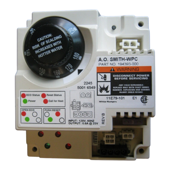
The 11E79 control is a solid-state thermostat control for
gas fired commercial water heater applications. The 11E79
supplies a relay switched output for damper or inducer
fan applications, and a "Call for Heat" signal or power to
energize a gas valve. The 11E79 receives input signals from
a temperature probe and Electrical Cutoff (ECO). It controls
temperature with an integrated temperature control knob. The
diagnostic features of the 11E79 make is easy to diagnose
system faults and issues.
CAUTION
!
Application of this type of control may cause flame
rollout on initial startup and could cause personal
injury and/or property damage.
Replace only with exact model number, including
dash number. Failure to use exact replacement control
could cause personal injury and/or property damage.
CAUTION
!
To prevent electrical shock and/or equipment damage,
disconnect electric power system at main fuse or
circuit breaker box until installation is complete.
This control is not intended for use in locations where
it may come in direct contact with water. Suitable
protection must be provided to shield the control from
exposure to water (dripping, spraying, rain, etc.).
Label all wires prior to disconnection when servicing
controls. Wiring errors can cause improper and
dangerous operation.
Following installation or replacement, follow appliance
manufacturers'
recommended
instructions to insure proper operation.
Do not exceed specified voltage of circuits. Higher
voltage will damage control and could cause shock or
fire hazard.
Replace a 11E79-XXX control with an approved model
number as indicated on the cross reference table below:
OEM Model
11E79-101
11E79-301
11E79-400
Do not short out terminals on gas valve or primary
control to test. Short or incorrect wiring will damage
the comfort control and could cause personal injury
and/or property damage.
FIRE, SHOCK AND EXPLOSION HAZARDS
• Shut off main gas to appliance for service or until
• Disconnect electric power before servicing.
• Do not exceed the specified voltage.
• Replace this control with only the exact model num-
• Protect the control from direct contact with water
• If the control has been in direct contact with water,
• Label all wires before disconnection when servic-
installation/service
• Route and secure wiring away from flame.
• Ensure proper earth grounding of appliance.
• Ensure proper connection of line neutral and line
• Do not take control apart, there are no serviceable
• Do not use control if it has been flooded.
• Never stand on the control or use as a step.
www.white-rodgers.com
www.emersonclimate.com
11E79
INTEGRATED WATER
HEATER CONTROL
INSTALLATION INSTRUCTIONS
11E79 Model Number Replacement Cross Reference Table
Approved Replacement
11E79-901
11E79-901
None
WARNING
!
WARNING
!
installation is complete.
ber listed above.
(dripping, spraying, rain, etc.)
replace the control.
ing controls. Wiring errors can cause improper and
dangerous operation.
hot wires.
parts inside.
DESCRIPTION
Temperature Range
120°F to 180°F
120°F to 180°F
120°F to 185°F
PRECAUTIONS
PART NO. 37-7512A
1403
Advertisement

Related Manuals for White Rodgers 11E79


Summary of Contents for White Rodgers 11E79
- Page 1 11E79 Model Number Replacement Cross Reference Table fan applications, and a “Call for Heat” signal or power to energize a gas valve. The 11E79 receives input signals from OEM Model Approved Replacement Temperature Range a temperature probe and Electrical Cutoff (ECO).
- Page 2 3. Note the temperature setting of the dial. previously removed. 4. Remove any cover that may be surrounding the 11E79 2. Replace the four wire connectors that were removed in control. step 5 above.
- Page 3 Viewed from wire side POWER CALL FOR LINE HOT Mates with AMP HEAT LINE NEUTRAL Connector 1-480698-0 and socket 350550-1 5.030 3 AMP FUSE Figure 3 - 11E79-101 50B66 11E79 7A20-1 4B-1 4A-3 4A-4 LINE HOT 2B-1 XFMR HOT Fuse...
- Page 4 WIRING DIAGRAMS IND HOT IND NEUTRAL 50B68-603 11E79 7A20-1 4B-1 4A-3 4A-4 2B-1 LINE HOT XFMR HOT Fuse 4A-2 120 VAC 24 VAC 2B-2 XFMR NEU 4A-1 LINE NEU PROBE TR4B-2 7A20-2 2A-1 Reset 4B-4 2A-2 BOTTOM PROBE 4B-3 FLAME...