Advertisement
Quick Links
CO
sensor CO
2
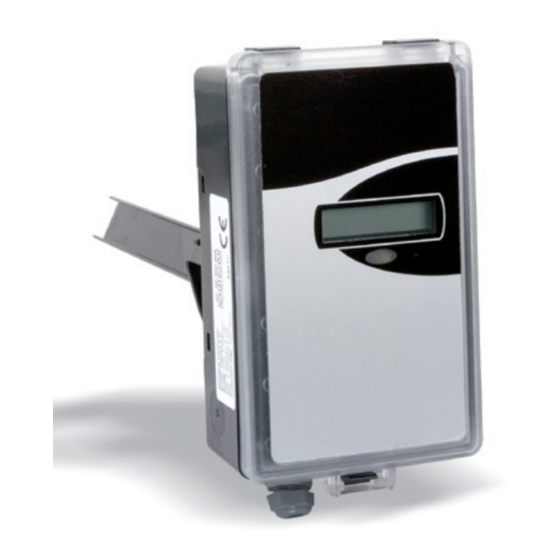
for interior room (W) or duct (K) installation
Duct installation (K)
Technical Data
CO
sensor:
Non-dispersive infrared techno-
2
logy (NDIR) with automatic base
correction
Sensor range - CO
:
0 – 3,000 ppm (factory calibration:
2
0 – 2,000 ppm)
Error limits - CO
:
± 3 0 ppm ± 3 % of the sensor reading
2
Repeatability accuracy: ± 2 0 ppm ± 1 % of the sensor reading
CO
pressure sensitivity: + 1 .6 % of sensor reading per kPa
2
variance from standard pressure
(100 kPa)
Annual zero point drift: < ± 1 0 ppm
CE marking:
2004 / 108 / EC (EMC)
Service interval:
5 years (recommended
for the first inspection)
Service life:
> 15 years
Ambient conditions:
Humidity 0 – 95 % RH,
(non-condensing)
Storage temperature: - 2 0 – + 7 0 °C
Operating temperature: 0 – 50 °C
Protection type:
IP 30 (W), IP 65 (K)
Dimensions (L x W x D): See dimensioned drawing
Weight:
Approx. 80 g (W) / 260 g (K)
Power supply:
24 V AC / DC ± 2 0 %
50 / 60 Hz
Power consumption:
2 watts
-W-LC / CO
2
2
Wall housing (W)
Sensor ventilation air conditioning | Data sheet No. 14106 | Version 06-2012 | 1 | 4
-K-LC
•
A utomatic internal self-calibration and
self-diagnostics with service intervals in
excess of 5 years.
•
L atest generation (NDIR) infrared technology
for measuring carbon-dioxide gas.
•
Multi-functional detection and control of CO
•
Two linear analog outputs for CO
•
LCD display optional
•
F or controlling ventilation demand as a
function of CO
concentration (recommended
2
threshold < 1,000 ppm)
Heat up time:
Response time T 1/e:
Run-in period:
Screw terminals:
Outputs
Analog output:
Output resolution:
Analog output accuracy: ± 2 % of sensor reading ± 50 mV
Configurations
•
Without display: CO
-W-LC
2
•
With display: CO
-W-DLC
2
•
Air duct installation without display: CO
•
Air duct installation with display: CO
•
S ee Data sheet No. 14101 for configurations with
additional temperature sensor
2
15 min
< 10 s at 30 cc/min flow-through,
< 3 min on diffusion
3 weeks after startup
Max. 1.5 mm²
2 linear analog outputs
OUT1 and OUT2 for CO
2
OUT1: fixed 0 – 10 V DC (R
> 5 kΩ)
Load
OUT2: 2 – 10 V or 4 – 20 mA
(R
≤ 500 Ω) adjustable with
Load
jumper.
10 mV
-K-LC
2
-K-DLC
2
2
Advertisement

Summary of Contents for Oppermann Regelgeräte CO2-W-LC
- Page 1 sensor CO -W-LC / CO -K-LC for interior room (W) or duct (K) installation • A utomatic internal self-calibration and Wall housing (W) self-diagnostics with service intervals in excess of 5 years. • L atest generation (NDIR) infrared technology for measuring carbon-dioxide gas. • Multi-functional detection and control of CO • Two linear analog outputs for CO • LCD display optional • F or controlling ventilation demand as a Duct installation (K) function of CO concentration (recommended threshold < 1,000 ppm) Technical Data sensor:...
- Page 2 sensor CO -W-LC / CO -K-LC Product description Applications The CO sensor is a fully digital sensor unit for detecting persons in The carbon dioxide concentration is generally accepted as a rooms. It is designed to measure the carbon dioxide concentration good indicator for the occupancy load on a room. Sufficient ven- in air to control the ventilation system as required. The sensor tilation can also counteract the spread of viruses and bacteria, consists of a membrane connected to a measurement cavity. The the cause for illnesses, absenteeism, and the resulting loss of diffusion technology used on this carbon dioxide sensor facilitates productivity. a stable and reliable device with high accuracy. The LCD display Studies demonstrate that controlling ventilation based on con- shows CO in ppm (option). Self calibration is automatically perfor- trolling CO can cut heating costs. med every time after the power supply is connected, and then in regularly recurring intervals. To ensure optimum self-calibration, the ventilation should supply a normal CO concentration for several minutes in intervals of at least one week. Electrical connection The sensor has two analog outputs OUT1 and OUT2 that both output a linear signal corresponding to the sensor range of the sensor. Output OUT 1 is permanently set to 0 – 10 V DC. Jumper setting for output 2 (OUT 2) = Option Display 2 –...
- Page 3 sensor CO -W-LC / CO -K-LC Installation Wall version installation Please observe these instructions. Attention: the correct positioning and connection of cables to All work (such as installation, electrical connection, startup, trade standards is a basic condition for proper functionality. operation, and maintenance) must only be performed by suf- Ventilation is particularly important. ficiently qualified tradesmen. The respectively applicable local Note the following instructions: • rules and regulations (e.g. national building codes, electrical/ T he sensor must be mounted vertically on an interior wall. • E nsure unrestricted air circulation on inlets and outlets. VDE regulations, etc.) must be observed. Installers and opera- • ting entities are required to sufficiently familiarize themselves A ttention: No additional openings on the housing or other before startup. Read the product description before operating measures to modify air circulation and heat distribution are the equipment. Verify that the product can be used for the permitted on the device. • relevant application without restrictions. We are not liable for O nly install the sensor where it is not exposed to strong light, printing errors and changes after printing. Appropriate use heat, sun irradiation, or airflow. • implies compliance with operating and installation instruc- W ait until conditions have stabilized.
- Page 4 sensor CO -W-LC / CO -K-LC Installation of duct version K • The correct positioning and connection of cables to trade Probe tube installation: standards, as well as proper sealing is a basic condition for Drill a Ø 25 mm (10) for the probe tube (1) and 2 Ø 4 mm for proper functionality. Note the following instructions: the mounting screws (5) at a suitable location into the duct. • Attention: Due to the pressure differential between the duct Then mount the probe tube including gasket (2) to the duct and the environment, the seal and cable feed-through must with screws (5). Note that the largest tap (3) is located on the be installed with special care. Incorrect readings can be bayonet lock of the probe tube. If necessary, seal the area of the result of air infiltration. No additional openings on the the gasket (2) with additional sealant.. • housing or other measures to modify air circulation and heat Housing installation: distribution are permitted on the device. If necessary, seal The housing with factory-installed O-ring (6) and electronics (7) the duct inlet with additional sealant if the included gasket is simply connected to the probe tube with the bayonet lock. is insufficient by itself (e.g. on smaller radii / pipes). Engage the upper side of the housing lightly in a counter- • Cable bushings in particular must be sealed properly. Never clockwise direction from the largest tap (3) of the probe tube insert more than one cable per cable bushing, since leaks and then rotate the housing to the right (see supplemental can result in incorrect readings. Only install the sensor drawing 1 2). Insert the cable into the cable thread (9) and / temperature transmitter for...