Advertisement
Quick Links
Instruction
Manual
SIGNAL SELECTOR
Thank you for selecting another fine
Please check the description given on the rating label of this unit to
make sure that it meets your specifications and be sure to read this
instruction manual before using the product.
This manual outlines the operation, connection and adjustment
procedures of this product.
The unit has been manufactured and inspected according to our strict
quality control standard. If you should find a defect including damage
incurred during transportation, contact us or the dealer where you
purchased it immediately.
○PACKAGE INCLUDES:
・Isolation converter.........................1
・Base socket.................................1
* For details of models and specifications, please download the
product catalog from our website, and then check it.
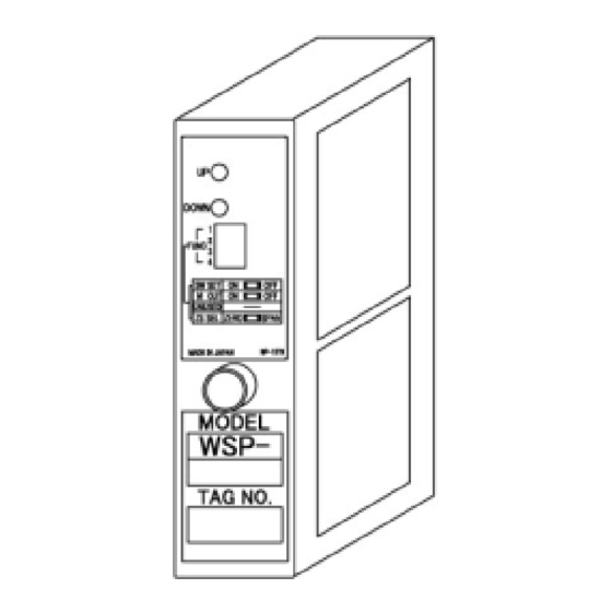
1.Overview
This unit is a plug-in type signal converter that receives two
analog signals and automatically selects the higher or lower of
them and outputs it.
2.Functions and Features
・Output zero span can be adjusted by front DIPSW
・Highly reliable design that is not affected by signal source
resistance and receiving resistance
・Realization of 5-year warranty by long-life design
・Compatible with worldwide power supply
・Compliant with CE marking
3.Precautions
1)
Power supply:
・ Check the rated voltage on the rating label, and use the product
within the range of each of the following ratings.
① 100 to 240VAC
100 to 240VAC ±10% (50/60 Hz) approx. 5.5 VA
② 24VDC
24VDC ±10%, Approx. 100 mA
③ 100~120VDC
100~120VDC ±10%, Approx. 25mA
2)
Insulation resistance:
Mutual between input - output - power supply
terminal
100MΩ or more/DC500V
Non-isolated between 2 input terminals
3)
Withstand voltage:
Mutual between input - output - power supply
terminal
AC2000V 1 minute
4) Handling
· When removing or installing the main unit from the
socket, be sure to shut off the power supply and input
signal for safety.
・When touching the screws on the main unit or operating
the output adjustment switch, touch a metal object to
remove static electricity before doing so.
5) Installation
WSP-SHS
WSP-SLS
product.
・Please use indoors.
・When installing in a place with a lot of dust, metal
powder, etc., store it in a dust-proof housing and
take heat dissipation measures.
・Avoid vibrations and impacts as much as possible,
as they may cause failure.
・Install in a place where the ambient temperature
does not exceed the range of -5 to 55°C.
・Install in a place where the ambient humidity is 90% RH
or less (non-freezing, non-condensing).
・Do not block the ventilation openings of the
main unit.
5) Wiring
・Do not wire the power supply line, input line, or
output line near noise sources, relay drive lines, or
high-frequency lines.
・Avoid bundling together lines on which noise is
superimposed or storing them in the same duct.
6) Others
・The unit can be operated immediately after turning
on the power, but 30 minutes of energization is
required to satisfy all performance requirements.
4.Outline Dimensions
5.Circuit Diagram
Digital
Analog input
calculation
circuit
circuit
Analog input
circuit
Base socket
6. Mounting
Close mounting is possible, but please leave a space of
6.5mm to 7mm or more for heat dissipation.
As shown in the figure above, a 6.5mm interval can be created
with a 29.5mm pitch.
6-16-19, JINGUMAE, SIBUYA-KU, TOKYO 150-0001, JAPAN
Phone: +81-3-3400-6147 FAX: +81-3-3409-3156
Output circuit
Power
circuit
2-M3 or M4
Or φ4.5 hole
Unit : mm
1/3
IM0346-03
Advertisement

Summary of Contents for WATANABE WSP-SHS
- Page 1 ・Please use indoors. Instruction ・When installing in a place with a lot of dust, metal WSP-SHS powder, etc., store it in a dust-proof housing and WSP-SLS Manual take heat dissipation measures. ・Avoid vibrations and impacts as much as possible, as they may cause failure.
- Page 2 Output signal Input signal ①=No.1 Input signal ②=No.2 Input signal ③=Output signal ○In case High selector (WSP-SHS) ※ Do not connect to NC terminal Output signal Input signal 9. Output Adjustment method The unit has been calibrated at the time of shipment, so no output adjustment is necessary as long as it is used according to the specifications at the time of ordering.
- Page 3 11. Simulation Output Function The instrument has a simulated output function for connection tests, etc. Simulated output is performed by operating the setting switch on the front of the instrument. (For the switch position, refer to the diagram in section 9.) ○...