Advertisement
Quick Links
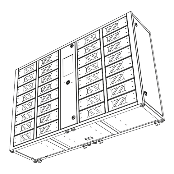
GIA 32 Bay
Touchscreen Charging Locker
1
9
2
10
3
11
4
12
5
13
6
14
7
15
8
16
Ø8mm
M6 screw
1. Drill 4 x Ø8mm holes on wall according to
the drawing. Fix 4 x screw studs and 4 x
screws on wall.
2. Leave a 5mm gap off the wall for hanging
the GIA Locker.
Ø8mm
M6 screw
22
401
INSTALLATION GUIDE
17
25
18
26
19
27
20
28
21
29
22
30
23
31
24
32
972
Ø8mm
M6 screw
Ø8mm
M6 screw
401
126
22
5. Fix 4 x screw studs in holes.
6. Fix 4 x M4 screws to secure the unit in place.
3. Fix 4 x L-Shape Rack on the bottom of
the GIA with 8 x M3 screws.
4. Mark the holes on wall. Drill 4 x Ø6mm
holes on wall according to the Mark.
Ø6mm
Advertisement

Summary of Contents for pagertec GIA 32 Bay
- Page 1 GIA 32 Bay Touchscreen Charging Locker INSTALLATION GUIDE 3. Fix 4 x L-Shape Rack on the bottom of Ø8mm the GIA with 8 x M3 screws. Ø8mm M6 screw 4. Mark the holes on wall. Drill 4 x Ø6mm M6 screw holes on wall according to the Mark.
- Page 2 B. Replace Cable 4. Unplug USB Cable. 5. Take out the cable through the hole. Replace charging cable 1-8 from left door. Replace charging cable 9-16 from middle door. Replace charging cable 17-24 from back door. Replace charging cable 25-32 from right door. 1.
- Page 3 F. Specifications C. Emergency D. Reset to factory admin password Administrative Mode 10. Open the front door by using the key - Input : AC 100 - 240V / 50~60Hz provided. - Output (per locker box) : 5V/2.4A Max To enter the Administrator Mode, tap the hidden Gear - Type C Cable, Lightning Cable, Micro USB Cable Icon at the top right corner of the main screen.