Advertisement
Quick Links
USER'S MANUAL
DC Modular
le installation | Hoofdkabel installatie
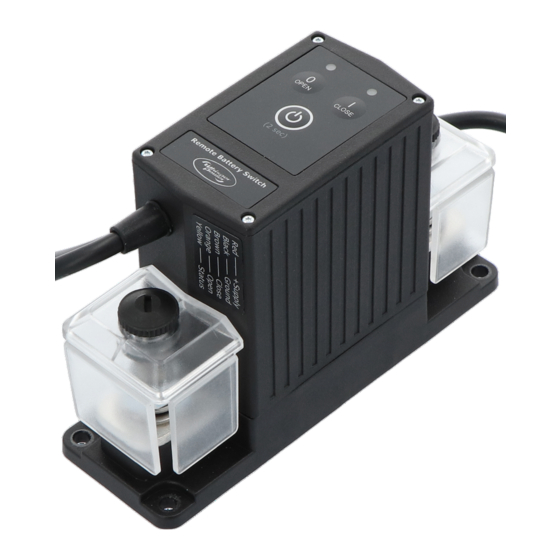
Remote Battery Switch
Main cable installation | Hoofdkabel installatie
Main cable installation | Hoofdkabel installatie
Main cable installation | Hoofdkabel installatie
!
Only hand tighten thumbscrews
Draai de duimschroeven alleen
met de hand vast
Assembly sequence:
Assembly sequence:
Assemblage volgorde:
Assemblage volgorde:
Assembly sequence:
Nut | Moer
Assemblage volgorde:
Assembly sequence:
Nut | Moer
Spring washer | Veerring
Assemblage volgorde:
Spring washer | Veerring
Washer | Ring
Nut | Moer
Washer | Ring
Spring washer | Veerring
Nut | Moer
Washer | Ring
Spring washer | Veerring
Washer | Ring
Cable lugs | Krimpogen
Cable lugs | Krimpogen
Cable lugs | Krimpogen
Cable lugs | Krimpogen
Wiring example | Bedradingsvoorbeeld
Busbar
Wiring example | Bedradingsvoorbeeld
Busbar
xample | Bedradingsvoorbeeld
Busbar
Busbar
Busbar
Wire | Draad
Standard function | Standaard functie
Busbar
Red | Rood
+Vdc continuous supply | +Vdc continue voeding
Black | Zwart
Brown | Bruin
+Vdc pulse closes contact | +Vdc puls sluit contact
Orange | Oranje
+Vdc pulse opens contact | +Vdc puls opent contact
Yellow | Geel 1)
Status (
1) The Status output is a ground referenced open collector port with a
maximum switching capacity of 34V / 100mA (Rout ò 10 )
1) De Status uitgang is een aan massa gerefereerde open collector poort met
een maximale schakelcapaciteit van 34V / 100mA (Ruit ò 10 )
Fuseholder
5A - 8A fuse
Zekeringhouder
5 - 8A zekering
A
Fuseholder
5A - 8A fuse
5 - 8A zekering
A
Zekeringhouder
1A fuse
1A zekering
1A fuse
1A zekering
Ground
Massa
Ground
der
5A - 8A fuse
Massa
5 - 8A zekering
A
Battery | Accu
ouder
3
1
Battery | Accu
1A fuse
Close
Open
1A zekering
Sluiten
Openen
General operation | Algemene werking
General operation | Algemene werking
Ground
2
Massa
Green flash - contact open
Green flash - contact closed
Green flash - contact open
Green flash - contact closed
External momentary switch
Red flash - error mode
Red flash - error mode
( art.no. 5095000-1)
Red flash - error mode
Red flash - error mode
Battery | Accu
Groen knipperend - contact open
Groen knipperend - contact gesloten
Groen knipperend - contact open
Groen knipperend - contact gesloten
Externe momentschakelaar
Rood knipperend - foutmodus
Rood knipperend - foutmodus
( art.nr. 5095000-1)
Rood knipperend - foutmodus
Rood knipperend - foutmodus
operation | Algemene werking
Open contact
Close contact
0
I
Open contact
Close contact
0
I
Open contact
Sluit contact
h - contact open
Green flash - contact closed
Open contact
OPEN
CLOSE
Sluit contact
OPEN
CLOSE
- error mode
Red flash - error mode
Power button. Press 2 seconds to turn the RBS
Power button. Press 2 seconds to turn the RBS
on or off. When turned off, the
Groen knipperend - contact gesloten
pperend - contact open
on or off. When turned off, the
automatically open the contact. In off mode, the
perend - foutmodus
Rood knipperend - foutmodus
automatically open the contact. In off mode, the
RBS
will ignore any control wire commands.
RBS
will ignore any control wire commands.
( sec)
2
( sec)
2
Aan/uit knop. Druk 2 seconden om de
Aan/uit knop. Druk 2 seconden om de
uit te schakelen. Wanneer deze wordt uitgeschakeld,
uit te schakelen. Wanneer deze wordt uitgeschakeld,
zal het contact automatisch geopend worden. In de
zal het contact automatisch geopend worden. In de
uit stand zullen alle stuurkabel commandoís
uit stand zullen alle stuurkabel commandoís
contact
Close contact
genegeerd worden.
genegeerd worden.
0
I
ontact
Sluit contact
OPEN
CLOSE
Power button. Press 2 seconds to turn the RBS
TBS
TBS
Electronics
Electronics
BV
BV
| De Marowijne 3 | 1689
| De Marowijne 3 | 1689
AR
AR
Zwaag | The Netherlands | www.tbs-electronics.com
Zwaag | The Netherlands | www.tbs-electronics.com
on or off. When turned off, the
RBS
will
automatically open the contact. In off mode, the
RBS
will ignore any control wire commands.
( sec)
2
Aan/uit knop. Druk 2 seconden om de
Dimensions | Afmetingen
R = 5mm (x4)
Dimensions | Afmetingen
R = 5mm (x4)
Dimensions | Afmetingen
R = 5mm (x4)
138.0mm
138.0mm
138.0mm
150.0mm
150.0mm
150.0mm
Error table | Fouttabel
Error table | Fouttabel
Wire | Draad
Standard function | Standaard functie
Error table (both
Error table | Fouttabel
Fouttabel (beide
Red | Rood
+Vdc continuous supply | +Vdc continue voeding
Wire | Draad
Standard function | Standaard functie
Cause | Oorzaak
Error table (both
Black | Zwart
Ground | Massa
Fouttabel (beide
Error table (both
LED
Red | Rood
+Vdc continuous supply | +Vdc continue voeding
Supply voltage too low
Brown | Bruin
+Vdc pulse closes contact | +Vdc puls sluit contact
Fouttabel (beide
LED
Cause | Oorzaak
Voedingsspanning te laag
Black | Zwart
Ground | Massa
Orange | Oranje
+Vdc pulse opens contact | +Vdc puls opent contact
Supply voltage too low
Cause | Oorzaak
Supply voltage too high
Brown | Bruin
+Vdc pulse closes contact | +Vdc puls sluit contact
Ground | Massa
Voedingsspanning te laag
Voedingsspanning te hoog
Yellow | Geel 1)
Status (
LED
) output |
Status (
LED
) uitgang
1)
Orange | Oranje
+Vdc pulse opens contact | +Vdc puls opent contact
Supply voltage too low
Supply voltage too high
RBS Temperature too high
1) The Status output is a ground referenced open collector port with a
Voedingsspanning te laag
Voedingsspanning te hoog
Yellow | Geel 1)
Status (
LED
) output |
Status (
LED
) uitgang
1)
RBS temperatuur te hoog
maximum switching capacity of 34V / 100mA (Rout ò 10 )
O
1) De Status uitgang is een aan massa gerefereerde open collector poort met
RBS Temperature too high
Supply voltage too high
1) The Status output is a ground referenced open collector port with a
RBS temperatuur te hoog
een maximale schakelcapaciteit van 34V / 100mA (Ruit ò 10 )
O
maximum switching capacity of 34V / 100mA (Rout ò 10 )
O
Voedingsspanning te hoog
LED
) output |
Status (
LED
) uitgang
1)
1) De Status uitgang is een aan massa gerefereerde open collector poort met
Contacts are welded
een maximale schakelcapaciteit van 34V / 100mA (Ruit ò 10 )
O
RBS Temperature too high
Contacten zijn verkleefd
RBS temperatuur te hoog
Contacts are welded
O
Contacten zijn verkleefd
Change control mode | Wijzig stuurmodus
O
Change control mode | Wijzig stuurmodus
When in off mode, press all three buttons simultaneously for three seconds to enter the setup mode:
Contacts are welded
Contacten zijn verkleefd
Vanuit de uit-stand alle drie knoppen tegelijk ingedrukt houden voor drie seconden om de setup
When in off mode, press all three buttons simultaneously for three seconds to enter the setup mode:
modus te activeren:
Vanuit de uit-stand alle drie knoppen tegelijk ingedrukt houden voor drie seconden om de setup
+
modus te activeren:
+
Change control mode | Wijzig stuurmodus
0
3
1
7
OPEN
When in off mode, press all three buttons simultaneously for three seconds to enter the setup mode:
3
1
7
Step through the control modes by pressing the
(3 sec)
Close
Open
Vanuit de uit-stand alle drie knoppen tegelijk ingedrukt houden voor drie seconden om de setup
Stap door de controlmodus opties m.b.v. de
OPEN
Openen
Step through the control modes by pressing the
OPEN
Sluiten
Close
Open
modus te activeren:
R
Stap door de controlmodus opties m.b.v. de
+
OPEN
+
(omhoog) of
Openen
Sluiten
Control mode table | Stuurmodus tabel
2
8
R
0
Control mode table | Stuurmodus tabel
2
8
Mode no.
Open LED
Close LED
Control mode
OPEN
External momentary switch
Modus nr.
Open LED
Close LED
Control modus
Mode no.
Open LED
Close LED
Control mode
( art.no. 5095000-1)
External momentary switch
7
Modus nr.
Open LED
Close LED
(3 sec)
Control modus
Externe momentschakelaar
( art.no. 5095000-1)
2-wire, no contact change at power-up
G
1
( art.nr. 5095000-1)
Externe momentschakelaar
2-draads, geen contact wijziging bij opstarten
Step through the control modes by pressing the
2-wire, no contact change at power-up
OPEN
(up) or
1
G
( art.nr. 5095000-1)
2-draads, geen contact wijziging bij opstarten
Stap door de controlmodus opties m.b.v. de
OPEN
(omhoog) of
2-wire, contact closes at power-up
2
G
G
2-draads, contact sluit bij opstarten
R
2-wire, contact closes at power-up
2
G
G
2-draads, contact sluit bij opstarten
Control mode table | Stuurmodus tabel
2-wire, contact opens at power-up
8
O
3
2-wire, contact opens at power-up
2-draads, contact opent bij opstarten
O
3
Mode no.
Open LED
Close LED
Control mode
2-draads, contact opent bij opstarten
single-wire, normally open contact
Modus nr.
Open LED
Close LED
O
Control modus
4
single-wire, normally open contact
O
enkeldraads, normaal geopend contact
4
enkeldraads, normaal geopend contact
2-wire, no contact change at power-up
1
G
single-wire, normally closed contact
O
O
5
2-draads, geen contact wijziging bij opstarten
single-wire, normally closed contact
O
O
enkeldraads, normaal geloten contact
5
enkeldraads, normaal geloten contact
2-wire, contact closes at power-up
2
G
When the desired control mode is selected, press the Power button for 2 seconds to save the setting.
G
When the desired control mode is selected, press the Power button for 2 seconds to save the setting.
2-draads, contact sluit bij opstarten
Press the Power button again for 2 seconds to activate the
Press the Power button again for 2 seconds to activate the
Wanneer de gewenste controlmodus geselecteerd is, druk op de aan/uit knop voor 2 seconden om de
2-wire, contact opens at power-up
3
O
Wanneer de gewenste controlmodus geselecteerd is, druk op de aan/uit knop voor 2 seconden om de
instelling op te slaan. Druk wederom 2 seconden op de aan/uit knop om de
2-draads, contact opent bij opstarten
instelling op te slaan. Druk wederom 2 seconden op de aan/uit knop om de
nieuwe controlmodus.
nieuwe controlmodus.
single-wire, normally open contact
O
4
RBS
will
Modes 1, 2 & 3:
+Vdc pulse on brown wire to close, +Vdc pulse on orange wire to open.
enkeldraads, normaal geopend contact
RBS
will
Modes 1, 2 & 3:
+Vdc pulse on brown wire to close, +Vdc pulse on orange wire to open.
+Vdc puls op bruine draad voor sluiten, +Vdc puls op oranje draad voor openen.
+Vdc puls op bruine draad voor sluiten, +Vdc puls op oranje draad voor openen.
single-wire, normally closed contact
O
O
5
Mode 4:
+Vdc continuous on brown wire to close, 0Vdc on brown wire to open. Orange wire
Mode 4:
+Vdc continuous on brown wire to close, 0Vdc on brown wire to open. Orange wire
enkeldraads, normaal geloten contact
RBS
in- of
RBS
in- of
not used.
not used.
+Vdc continu op bruine draad voor sluiten, 0Vdc op bruine draad voor openen.
+Vdc continu op bruine draad voor sluiten, 0Vdc op bruine draad voor openen.
When the desired control mode is selected, press the Power button for 2 seconds to save the setting.
Oranje draad niet gebruikt.
Oranje draad niet gebruikt.
Press the Power button again for 2 seconds to activate the
RBS
Mode 5:
Mode 5:
+Vdc continuous on brown wire to open, 0Vdc on brown wire to close. Orange wire
+Vdc continuous on brown wire to open, 0Vdc on brown wire to close. Orange wire
Wanneer de gewenste controlmodus geselecteerd is, druk op de aan/uit knop voor 2 seconden om de
not used.
not used.
instelling op te slaan. Druk wederom 2 seconden op de aan/uit knop om de
+Vdc continu op bruine draad voor openen, 0Vdc op bruine draad voor sluiten.
+Vdc continu op bruine draad voor openen, 0Vdc op bruine draad voor sluiten.
nieuwe controlmodus.
Oranje draad niet gebruikt.
Oranje draad niet gebruikt.
Modes 1, 2 & 3:
+Vdc pulse on brown wire to close, +Vdc pulse on orange wire to open.
+Vdc puls op bruine draad voor sluiten, +Vdc puls op oranje draad voor openen.
Mode 4:
+Vdc continuous on brown wire to close, 0Vdc on brown wire to open. Orange wire
RBS
in- of
not used.
Installation details
EN
Installation details
!
Precautions
EN
Please install this product in a dry indoor location, as close as possible to the battery. To be installed
Installation details
1
!
Precautions
EN
PRECAUTIONS
only by qualified technicians.
To avoid fire hazards, use correctly sized cables which are suitable to carry the expected load currents
2
Please install this product in a dry indoor location, as close as possible to the battery. To be installed
1
!
Precautions
in your application. The maximum continuous
only by qualified technicians.
cable size of at least 200mm is connected to the M10 studs. Or when the
2
To avoid fire hazards, use correctly sized cables which are suitable to carry the expected load currents
2
system containing large busbars and fuseholders.
in your application. The maximum continuous
Please install this product in a dry indoor location, as close as possible to the battery. To be installed
1
cable size of at least 200mm is connected to the M10 studs. Or when the
2
only by qualified technicians.
To avoid fire hazards or damaging the
3
system containing large busbars and fuseholders.
To avoid fire hazards, use correctly sized cables which are suitable to carry the expected load currents
Please apply our recommended torque rating of 22Nm for the M10 nuts.
2
in your application. The maximum continuous
To avoid fire hazards or damaging the
3
To avoid fire hazards or damaging the
4
cable size of at least 200mm is connected to the M10 studs. Or when the
Please apply our recommended torque rating of 22Nm for the M10 nuts.
2
system containing large busbars and fuseholders.
placed directly below the nut. Never place washers between: busbar and
To avoid fire hazards or damaging the
4
on the same stud, busbar and linkplate or
To avoid fire hazards or damaging the
3
placed directly below the nut. Never place washers between: busbar and
Please apply our recommended torque rating of 22Nm for the M10 nuts.
on the same stud, busbar and linkplate or
Please make sure that all connection cables are properly strain relieved, to avoid excessive mechanical
5
To avoid fire hazards or damaging the
4
Please make sure that all connection cables are properly strain relieved, to avoid excessive mechanical
stress on the
5
RBS
.
placed directly below the nut. Never place washers between: busbar and
stress on the
RBS
.
on the same stud, busbar and linkplate or
RBS features
Please make sure that all connection cables are properly strain relieved, to avoid excessive mechanical
5
RBS features
REMOTE BATTERY SWITCH FEATURES
stress on the
RBS
.
RBS features
Smart high current magnetic latching relay, draws virtually no current in On (Close) or Off (Open)
Smart high current magnetic latching relay, draws virtually no current in On (Close) or Off (Open)
state.
state.
Silver alloy contacts and silver plated copper busbars, for maximum conductivity and high reliability
Smart high current magnetic latching relay, draws virtually no current in On (Close) or Off (Open)
Silver alloy contacts and silver plated copper busbars, for maximum conductivity and high reliability
when switching live loads.
state.
when switching live loads.
Local Open and Close buttons on top, to manually override the switch state.
Silver alloy contacts and silver plated copper busbars, for maximum conductivity and high reliability
Local Open and Close buttons on top, to manually override the switch state.
when switching live loads.
5 wire interface cable or external control
f
two wire or single wire On/Off control. Includes status wire for controlling indicator light or providing
Local Open and Close buttons on top, to manually override the switch state.
5 wire interface cable or external control
f
feedback to
BMS
.
two wire or single wire On/Off control. Includes status wire for controlling indicator light or providing
5 wire interface cable or external control
f
feedback to
BMS
.
two wire or single wire On/Off control. Includes status wire for controlling indicator light or providing
Stainless steel studs, washers and nuts for optimal corrosion resistance.
50.0mm
feedback to
BMS
.
Unique grid optimized footprint allows space saving arrangements
Stainless steel studs, washers and nuts for optimal corrosion resistance.
50.0mm
Stainless steel studs, washers and nuts for optimal corrosion resistance.
50.0mm
Special fiber reinforced plastic
Unique grid optimized footprint allows space saving arrangements
Unique grid optimized footprint allows space saving arrangements
resistance and high strength.
Special fiber reinforced plastic
Special fiber reinforced plastic
housing
Robust transparent covers with breakouts to allow wire access from any direction.
resistance and high strength.
resistance and high strength.
Smart terminal design allows dual mirrored cable lug connections.
Robust transparent covers with breakouts to allow wire access from any direction.
Robust transparent covers with breakouts to allow wire access from any direction.
LED
s flashing red)
LED
s knipperen rood)
Smart terminal design allows dual mirrored cable lug connections.
Smart terminal design allows dual mirrored cable lug connections.
RBS specifications
LED
s flashing red)
Remedy | Remedie
LED
s knipperen rood)
s flashing red)
Increase supply voltage
RBS specifications
BATTERY SWITCH
s knipperen rood)
Remedy | Remedie
Verhoog voedingsspanning
12 VDC | 500 A
RBS specifications
Increase supply voltage
Parameter
Remedy | Remedie
Decrease supply voltage
Article Number
Verhoog voedingsspanning
Verlaag voedingsspanning
Increase supply voltage
Parameter
PARAMETER
Decrease supply voltage
Reduce the contact current, check all
Verhoog voedingsspanning
Verlaag voedingsspanning
cable connections
Contact circuit (electrical)
Rated voltage
Reduceer de stroom door het contact,
Parameter
Reduce the contact current, check all
Decrease supply voltage
controleer alle kabelverbindingen
cable connections
Nominal current @ 25C
Verlaag voedingsspanning
Contact circuit (electrical)
Rated voltage
Reduceer de stroom door het contact,
Replace the RBS
controleer alle kabelverbindingen
Cranking current (1 min.)
Reduce the contact current, check all
Vervang de RBS
Rated voltage
Nominal current @ 25∞C
cable connections
Replace the RBS
Contact circuit (electrical)
Nominal make /
Reduceer de stroom door het contact,
Vervang de RBS
Nominal current @ 25∞C
Cranking current (1 minute)
break current
controleer alle kabelverbindingen
Cranking current (1 minute)
Rated voltage
Nominal make / break current
Peak make /
Replace the RBS
break current
Nominal make / break current
Vervang de RBS
Nominal current @ 25∞C
Peak make / break current
CONTROL CIRCUIT (ELECTRICAL)
+
Cranking current (1 minute)
0
I
Peak make / break current
Coil / supply voltage
+
OPEN
CLOSE
I
(+ VDC)
Control circuit (electrical)
Nominal make / break current
(3 sec)
CLOSE
Control circuit (electrical)
Coil / supply current
Coil / supply voltage (+Vdc)
OPEN
(up) or
CLOSE
(down) buttons
(idle state) *
)
(omhoog) of
CLOSE
(omlaag) knoppen
Coil / supply voltage (+Vdc)
(up) or
CLOSE
(down) buttons
Peak make / break current
Coil / supply current (idle state)
CLOSE
(omlaag) knoppen
Coil / supply current
Coil / supply current (idle state)
I
(state change) *
Coil / supply current (state change)
)
CLOSE
Coil / supply current (state change)
GENERAL
Control circuit (electrical)
General
LED off
General
Remote control
By control wires
=
Remote control 1)
LED off
LED uit
Coil / supply voltage (+Vdc)
CLOSE
(down) buttons
=
Remote control 1)
Local control **
)
LED uit
LED green
CLOSE
(omlaag) knoppen
Local control
G
=
LED green
Coil / supply current (idle state)
LED groen
Local control
G
=
LED groen
Indicators
LED orange
Indicators
O
=
LED orange
Indicators
Coil / supply current (state change)
LED oranje
O
=
Mechanical life
Protected against
100000 cycles
LED oranje
Protected against
General
Electrical life
LED off
=
Mechanical life
Remote control 1)
Operating
Mechanical life
LED uit
-20 up to 60°C
temperature range
Electrical life
LED green
Electrical life
Local control
Connection stud/ DCM
G
=
LED groen
grid size
Operating temperature range
RBS
with the new control mode.
Operating temperature range
RBS
with the new control mode.
Indicators
LED orange
Protection class /weight
O
=
Connection studs /
DCM
grid size
LED oranje
RBS
te activeren met de
Connection studs /
DCM
grid size
RBS
te activeren met de
Dimensions
Protected against
Protection class / weight
Protection class / weight
(W x D x H) in mm
CE certified (EMC Directives UNECE Regulation 10 and 2014/30/EU,
Standards
Standards
Standards
Low voltage Directive 2014/35/EU, RoHS Directive 2011/65/EU and Ig-
Mechanical life
1) Panel switch with
LED
indicator optionally available (Art. no. 5095000-1)
1) Panel switch with
*
)
Due to the magnetic latch construction, the DCM-RBS draws virtually no current in the ON or OFF state.
LED
indicator optionally available (Art. no. 5095000-1)
Electrical life
A current draw only exists shortly (500 ms max.) when changing the state of the contact.
**
)
Using the top side buttons, one can manually override the switch state as commanded through the
Operating temperature range
with the new control mode.
control wires. A dedicated 'On / Standby' button also allows the user to put the DCM-RBS in a standby
mode with open contact. In this mode any command from the control wires and/or manual override
Connection studs /
DCM
grid size
RBS
te activeren met de
buttons are ignored.
Protection class / weight
Standards
WhisperPower BV | Kelvinlaan 82, 9207 JB Drachten, The Netherlands | Tel: +31 (0) 512 571 550 | sales@whisperpower.com | www.whisperpower.com
1) Panel switch with
LED
indicator optionally available (Art. no. 5095000-1)
NL
Installatiedetails
!
Voorzorgsmaatregelen
NL
VOORZORGSMAATREGELEN
Installeer dit product alleen in een droge omgeving, zo dicht mogelijk bij de accu. Installatie enkel te
1
!
Voorzorgsmaatregelen
RBS
current rating of 500A is only valid when a total
verrichten door een gekwalificeerd installateur.
RBS
is part of a
DC
Modular
Gebruik om brandgevaar te voorkomen alleen correct gedimensioneerde kabels, geschikt voor de te
2
RBS
current rating of 500A is only valid when a total
verwachten stromen. De maximale
Installeer dit product alleen in een droge omgeving, zo dicht mogelijk bij de accu. Installatie enkel te
1
RBS
is part of a
DC
Modular
M10 terminals een kwadratuur van minimaal 200mm hebben. Of wanneer de
verrichten door een gekwalificeerd installateur.
RBS
, please make sure that all nuts are securely tightened.
een
DC
Gebruik om brandgevaar te voorkomen alleen correct gedimensioneerde kabels, geschikt voor de te
2
RBS
RBS
current rating of 500A is only valid when a total
, please make sure that all nuts are securely tightened.
verwachten stromen. De maximale
Om brandgevaar te voorkomen, dient u er voor te zorgen dat alle moeren voldoende worden
3
RBS
, please make sure that
spring-
and
flat
washers are always
RBS
is part of a
DC
Modular
M10 terminals een kwadratuur van minimaal 200mm hebben. Of wanneer de
aangedraaid. Raadpleeg hiervoor on aanbevolen aandraaimoment
cable
lug, multiple
een
cable
DC
Modular systeem, er grote busbars en/of zekeringhouders mee in verbinding staan.
lugs
RBS
, please make sure that
spring-
and
flat
washers are always
Om schade aan de
4
cable
lug and linkplate.
RBS
, please make sure that all nuts are securely tightened.
Om brandgevaar te voorkomen, dient u er voor te zorgen dat alle moeren voldoende worden
cable
lug, multiple
cable
3
lugs
direct onder de moer te bevinden. Plaats ringen nooit tussen: busbar en krimpoog, meerdere
aangedraaid. Raadpleeg hiervoor on aanbevolen aandraaimoment
cable
lug and linkplate.
krimpogen op dezelfde bout, busbar en verbindingsplaat
RBS
, please make sure that
spring-
and
flat
washers are always
Om schade aan de
RBS
4
Zorg voor voldoende trekontlasting op alle kabels. Dit om een te hoge mechanische belasting op de
5
cable
lug, multiple
cable
lugs
direct onder de moer te bevinden. Plaats ringen nooit tussen: busbar en krimpoog, meerdere
RBS te voorkomen.
cable
lug and linkplate.
krimpogen op dezelfde bout, busbar en verbindingsplaat
Zorg voor voldoende trekontlasting op alle kabels. Dit om een te hoge mechanische belasting op de
5
RBS eigenschappen
REMOTE BATTERY SWITCH EIGENSCHAPPEN
RBS te voorkomen.
RBS eigenschappen
Slim bistabiel relais voor het schakelen van hoge stromen, verbruikt zelf vrijwel geen stroom in de ëaaní
(gesloten) of ëuití (geopende) stand.
Contacten van een zilver legering en verzilverde koperen aansluitplaten zorgen voor de beste geleiding
Slim bistabiel relais voor het schakelen van hoge stromen, verbruikt zelf vrijwel geen stroom in de ëaaní
en een hoge betrouwbaarheid bij het schakelen van belastingen.
(gesloten) of ëuití (geopende) stand.
Lokale ëOpení en ëCloseí knoppen kunnen de controle van het hoofdcontact overnemen.
Contacten van een zilver legering en verzilverde koperen aansluitplaten zorgen voor de beste geleiding
en een hoge betrouwbaarheid bij het schakelen van belastingen.
by panel switch, battery monitor or
BMS
.
Compatible with
5
-draads aansluitkabel voor externe besturing vanuit een paneel schakelaar, batterij monitor of BMS
Geschikt voor 2-draads en enkeldraads besturing van het hoofdcontact. Inclusief status draad voor
by panel switch, battery monitor or
BMS
.
Compatible with
Lokale ëOpení en ëCloseí knoppen kunnen de controle van het hoofdcontact overnemen.
sturing van indicator of terugkoppeling naar
by panel switch, battery monitor or
BMS
.
Compatible with
5
-draads aansluitkabel voor externe besturing vanuit een paneel schakelaar, batterij monitor of BMS
Geschikt voor 2-draads en enkeldraads besturing van het hoofdcontact. Inclusief status draad voor
Optimale corrosiebestendigheid door gebruik van
sturing van indicator of terugkoppeling naar
with other DC
Modular products.
Unieke raster gebaseerde basisafmetingen staan zeer compacte formaties van meerdere
Optimale corrosiebestendigheid door gebruik van
producten toe.
housing
offers excellent high temperature properties, good chemical
with other DC
Modular products.
with other DC
Modular products.
Unieke raster gebaseerde basisafmetingen staan zeer compacte formaties van meerdere
Speciale vezel versterkte kunststof
producten toe.
goede bestendigheid tegen chemische stoffen en een zeer hoge sterkte.
housing
offers excellent high temperature properties, good chemical
offers excellent high temperature properties, good chemical
Speciale vezel versterkte kunststof
T
ransparante afdekkappen met uitbreekbare kanten
goede bestendigheid tegen chemische stoffen en een zeer hoge sterkte.
Door een slim aansluitklem ontwerp kunnen twee krimpogen ook gespiegeld worden gemonteerd.
T
ransparante afdekkappen met uitbreekbare kanten
Door een slim aansluitklem ontwerp kunnen twee krimpogen ook gespiegeld worden gemonteerd.
RBS specificaties
REMOTE
REMOTE
REMOTE
BATTERY SWITCH
BATTERY SWITCH
RBS specificaties
24 VDC | 500 A
48 VDC | 350 A
DCM RBS
-
-12-500
DCM RBS
-
-24-500
Parameter
50214733
50214734
50214718
Artikelnummer
(art# 5074510)
(art# 5074520)
DCM RBS
-
-12-500
DCM RBS
-
-24-500
Parameter
PARAMETER
(art# 5074510)
(art# 5074520)
Contact circuit (elektrisch)
60 VDC
60 VDC
60 VDC
Rated voltage
DCM RBS
-
-12-500
DCM RBS
-
-24-500
500 A
500 A
500 A
Max. spanning @ 25C
60Vdc
Contact circuit (elektrisch)
Maximale spanning
(art# 5074510)
(art# 5074520)
1000 A
1000 A
1000 A
Aanloopstroom (1 min.)
60Vdc
500A (see Precaution #2)
Maximale spanning
Max. continustroom @ 25∞C
Nominal maak / ver-
500 A (0 - 34 VDC) / 350 A (35 - 60 VDC) (see precaution#2)
500A (see Precaution #2)
1000A
Max. continustroom @ 25∞C
Aanloopstroom (1 minuut)
breekstroom
1000A
60Vdc
Aanloopstroom (1 minuut)
500A (0 .. 34Vdc)
Nominale maak- / verbreekstroom
Piek maak / verbreek-
1600 A (0 - 34 VDC) / 1200 A (35 - 60 VDC)
350A (35 .. 60Vdc)
stroom
500A (0 .. 34Vdc)
Nominale maak- / verbreekstroom
500A (see Precaution #2)
350A (35 .. 60Vdc)
1600A (0 .. 34Vdc)
Piek maak- / verbreekstroom
BEDIENINGSCIRCUIT (ELEKTRISCH)
1200A (35 .. 60Vdc)
1000A
1600A (0 .. 34Vdc)
Piek maak- / verbreekstroom
Spoel / voedingsspan-
7.5 - 17 VDC
15 - 34 VDC
34 - 68 VDC
1200A (35 .. 60Vdc)
ning (+ VDC)
Besturingscircuit (elektrisch)
500A (0 .. 34Vdc)
Besturingscircuit (elektrisch)
350A (35 .. 60Vdc)
Spoel / voedingsstroom
7 .. 17Vdc
14 .. 34Vdc
Spoel / voedingsspanning (+Vdc)
< 100 μA
< 100 μA
< 100 μA
(rust *)
7 .. 17Vdc
14 .. 34Vdc
Spoel / voedingsspanning (+Vdc)
< 100 A
1600A (0 .. 34Vdc)
µ
Spoel / voedingsstroom (rust)
Spoel / voedingsstroom
< 6 A
< 100 A
< 3 A
µ
1200A (35 .. 60Vdc)
< 1.5 A
Spoel / voedingsstroom (rust)
(schakelen) *)
< 4A
< 3A
Spoel / voedingsstroom (schakelen)
< 4A
< 3A
Spoel / voedingsstroom (schakelen)
ALGEMEEN
Algemeen
Algemeen
By control wires
By control wires
Bediening op afstand
By control wires (length 40cm, max. 15m)
Bediening op afstand 1)
7 .. 17Vdc
14 .. 34Vdc
Top side buttons (ON/Standby, Close contact, Open contact)
By control wires (length 40cm, max. 15m)
Bediening op afstand 1)
Bediening lokaal **
On/Standby, Close contact, Open contact
Bediening lokaal
< 100 A
µ
On/Standby, Close contact, Open contact
Top side LEDs for Contact open,
Bediening lokaal
Indicatoren
Contact closed, Error and Setup
Contact open, Contact close, Error and Setup
Indicatoren
Contact open, Contact close, Error and Setup
< 4A
< 3A
Indicatoren
High temperature, High/Low supply voltage,
100000 cycles
100000 cycles
Mechanische levensduur
Beveiligd tegen
High temperature, High/Low supply voltage,
Beveiligd tegen
Ignition (
ISO
8846)
10000 cycles
10000 cycles
10000 cycles
Elektrische levensduur
Ignition (
ISO
8846)
100000 cycles
Mechanische levensduur
By control wires (length 40cm, max. 15m)
Werkingstemperatuur-
100000 cycles
Mechanische levensduur
-20 up to 60°C
-20 up to 60°C
bereik
10000 cycles (@ 400A/24V/resistive)
Elektrische levensduur
10000 cycles (@ 400A/24V/resistive)
On/Standby, Close contact, Open contact
Elektrische levensduur
Verbindingsbouten / ras-
M10 / 1 x 3
M10 / 1 x 3
M10 / 1 x 3
-20 .. +60∞C
termaat
Werkingstemperatuur (omgeving)
-20 .. +60∞C
Werkingstemperatuur (omgeving)
Contact open, Contact close, Error and Setup
Beschermingsklasse /
IP65 / 800 g
IP65 / 800 g
IP65 / 800 g
M10 / 1 x 3
Verbindingsbouten / rastermaat
gewicht
M10 / 1 x 3
Verbindingsbouten / rastermaat
High temperature, High/Low supply voltage,
50 x 94 x 150
50 x 94 x 150
50 x 94 x 150
Afmetingen (B x D x H) in
IP 65 / 800 grams
Beschermingsklasse / Gewicht
IP 65 / 800 grams
Beschermingsklasse / Gewicht
Ignition (
ISO
8846)
mm
EMC
: 2014/30/
EU
, Low voltage directive: 2014/35/
EU
,
Normen
EMC
: 2014/30/
EU
, Low voltage directive: 2014/35/
EU
,
Normen
Ro
HS
: 2011/65/
EU
, Automotive:
100000 cycles
EN
50498,
ISO
8846
Normen
Ro
HS
: 2011/65/
EU
, Automotive:
EN
50498,
ISO
8846
nition protection standard ISO 8846)
1) Paneelschakelaar met
1) Paneelschakelaar met
10000 cycles (@ 400A/24V/resistive)
*) Door de magnetische vergrendelingsconstructie trekt de DCM-RBS vrijwel geen stroom in de aan- of uitstand.
Er wordt slechts kort (max. 500 ms) stroom getrokken bij het veranderen van de toestand van het con-
-20 .. +60∞C
tact.**) Met behulp van de knoppen aan de bovenzijde kan men handmatig de schakeltoestand opheffen
zoals die via de besturingsdraden wordt bevolen. Een speciale 'On / Standby' knop stelt de gebruiker ook
M10 / 1 x 3
in staat de DCM-RBS in een stand-by modus met open contact te zetten. In deze modus worden alle
commando's van de besturingsdraden en/of handmatige overbruggingsknoppen genegeerd..
IP 65 / 800 grams
EMC
: 2014/30/
EU
, Low voltage directive: 2014/35/
EU
,
Ro
HS
: 2011/65/
EU
, Automotive:
EN
50498,
ISO
8846
Installatiedetails
NL
Installatiedetails
!
Voorzorgsmaatregelen
Installeer dit product alleen in een droge omgeving, zo dicht mogelijk bij de accu. Installatie
1
verrichten door een gekwalificeerd installateur.
Gebruik om brandgevaar te voorkomen alleen correct gedimensioneerde kabels, geschikt v
2
verwachten stromen. De maximale
RBS
stroom van 500A, is alleen geldig wanneer de kabel
M10 terminals een kwadratuur van minimaal 200mm hebben. Of wanneer de
2
een
DC
Modular systeem, er grote busbars en/of zekeringhouders mee in verbinding staan.
RBS
stroom van 500A, is alleen geldig wanneer de kabels op de
2
RBS
onderdeel is van
Om brandgevaar te voorkomen, dient u er voor te zorgen dat alle moeren voldoende worde
3
Modular systeem, er grote busbars en/of zekeringhouders mee in verbinding staan.
aangedraaid. Raadpleeg hiervoor on aanbevolen aandraaimoment
s
van
RBS
stroom van 500A, is alleen geldig wanneer de kabels op de
Om schade aan de
RBS
of brandgevaar te voorkomen, dienen de veerring en de vlakke ring
4
s
2
RBS
van
onderdeel is van
22Nm voor
de
M10 moeren.
direct onder de moer te bevinden. Plaats ringen nooit tussen: busbar en krimpoog, meerde
RBS
of brandgevaar te voorkomen, dienen de veerring en de vlakke ring zich altijd
krimpogen op dezelfde bout, busbar en verbindingsplaat
of
krimpoog en verbindingsplaat.
s
van
22Nm voor
de
M10 moeren.
of
krimpoog en verbindingsplaat.
Zorg voor voldoende trekontlasting op alle kabels. Dit om een te hoge mechanische belastin
5
of brandgevaar te voorkomen, dienen de veerring en de vlakke ring zich altijd
RBS te voorkomen.
of
krimpoog en verbindingsplaat.
RBS eigenschappen
Slim bistabiel relais voor het schakelen van hoge stromen, verbruikt zelf vrijwel geen stroom
(gesloten) of ëuití (geopende) stand.
Contacten van een zilver legering en verzilverde koperen aansluitplaten zorgen voor de bes
en een hoge betrouwbaarheid bij het schakelen van belastingen.
Lokale ëOpení en ëCloseí knoppen kunnen de controle van het hoofdcontact overnemen.
5-draads aansluitkabel voor externe besturing vanuit een paneel schakelaar, batterij monito
BMS
.
Geschikt voor 2-draads en enkeldraads besturing van het hoofdcontact. Inclusief status dra
.
sturing van indicator of terugkoppeling naar
BMS
.
RVS
bouten, ringen en moeren.
BMS
.
DC
Modular
Optimale corrosiebestendigheid door gebruik van
RVS
bouten, ringen en moeren.
RVS
bouten, ringen en moeren.
Unieke raster gebaseerde basisafmetingen staan zeer compacte formaties van meerdere DC
DC
Modular
behuizing
biedt uitstekende hoge temperatuur eigenschappen,
producten toe.
behuizing
biedt uitstekende hoge temperatuur eigenschappen,
Speciale vezel versterkte kunststof
behuizing
biedt uitstekende hoge temperatuur eigensch
voor
kabelverbindingen vanuit meerdere
hoeken
goede bestendigheid tegen chemische stoffen en een zeer hoge sterkte.
voor
kabelverbindingen vanuit meerdere
hoeken
.
T
ransparante afdekkappen met uitbreekbare kanten
voor
kabelverbindingen vanuit meerde
Door een slim aansluitklem ontwerp kunnen twee krimpogen ook gespiegeld worden gemo
REMOTE
REMOTE
REMOTE
BATTERY SWITCH
BATTERY SWITCH
BATTERY SWITCH
12 VDC | 500 A
24 VDC | 500 A
48 VDC | 350 A
RBS specificaties
DCM RBS
-
-12-500
DCM RBS
-
-24-500
50214733
50214734
50214718
(art# 5074510)
(art# 5074520)
DCM RBS
-
-12-500
DCM RBS
-
-24-500
(art# 5074510)
(art# 5074520)
60 VDC
60 VDC
60 VDC
Parameter
DCM RBS
-
-12-500
500 A
500 A
500 A
60Vdc
(art# 5074510)
1000 A
1000 A
1000 A
60Vdc
500A (zie voorzorgsmaatregel #2)
Contact circuit (elektrisch)
500 A (0 - 34 VDC) / 350 A (35 - 60 VDC) (zie voorzorgsmaatregel #2)
500A (zie voorzorgsmaatregel #2)
1000A
Maximale spanning
1000A
60Vdc
500A (0 .. 34Vdc)
1600 A (0 - 34 VDC) / 1200 A (35 - 60 VDC)
350A (35 .. 60Vdc)
500A (0 .. 34Vdc)
Max. continustroom @ 25∞C
500A (zie voorzorgsmaatregel #2)
350A (35 .. 60Vdc)
1600A (0 .. 34Vdc)
Aanloopstroom (1 minuut)
1200A (35 .. 60Vdc)
1000A
1600A (0 .. 34Vdc)
7.5 - 17 VDC
15 - 34 VDC
34 - 68 VDC
1200A (35 .. 60Vdc)
Nominale maak- / verbreekstroom
500A (0 .. 34Vdc)
350A (35 .. 60Vdc)
7 .. 17Vdc
14 .. 34Vdc
< 100 μA
< 100 μA
< 100 μA
7 .. 17Vdc
14 .. 34Vdc
Piek maak- / verbreekstroom
< 100 A
µ
1600A (0 .. 34Vdc)
< 6 A
< 100 A
µ
< 3 A
< 1.5 A
1200A (35 .. 60Vdc)
< 4A
< 3A
< 4A
< 3A
Besturingscircuit (elektrisch)
Door besturingsdraden
Via besturingsbedrading (lengte 40cm, max. 15m)
Spoel / voedingsspanning (+Vdc)
7 .. 17Vdc
Knoppen aan bovenzijde (AAN/Standby, Dicht contact, Open contact)
Via besturingsbedrading (lengte 40cm, max. 15m)
)
Aan/Standby, Sluit contact, Open contact
Spoel / voedingsstroom (rust)
< 100 A
LED's aan de bovenzijde voor Contact open, Contact gesloten, Fout en
Aan/Standby, Sluit contact, Open contact
Contact open, Contact gesloten, Fout en Instelmodus
Instelling
Spoel / voedingsstroom (schakelen)
Contact open, Contact gesloten, Fout en Instelmodus
< 4A
100000 cycli
Hoge temperatuur, Hoge/lage voedingsspanning,
100000 cycli
100000 cycli
Hoge temperatuur, Hoge/lage voedingsspanning,
Algemeen
ontsteking (
ISO
8846)
10000 cycli
10000 cycli
10000 cycli
ontsteking (
ISO
8846)
100000 cycli
Bediening op afstand 1)
Via besturingsbedrading (lengte 40cm, max. 1
100000 cycli
-20 tot 60°C
-20 tot 60°C
-20 tot 60°C
10000 cycli (@ 400A/24V/resistive)
Bediening lokaal
10000 cycli (@ 400A/24V/resistive)
Aan/Standby, Sluit contact, Open contact
M10 / 1 x 3
M10 / 1 x 3
M10 / 1 x 3
-20 .. +60∞C
-20 .. +60∞C
Indicatoren
Contact open, Contact gesloten, Fout en Instelm
IP65 / 800 g
IP65 / 800 g
IP65 / 800 g
M10 / 1 x 3
M10 / 1 x 3
Beveiligd tegen
Hoge temperatuur, Hoge/lage voedingsspann
IP 65 / 800 gram
50 x 94 x 150
IP 65 / 800 gram
50 x 94 x 150
50 x 94 x 150
ontsteking (
ISO
EMC
: 2014/30/
EU
, Low voltage directive: 2014/35/
EU
,
CE certified (EMC Directives UNECE Regulation 10 and 2014/30/EU,
EMC
: 2014/30/
EU
, Low voltage directive: 2014/35/
EU
,
Mechanische levensduur
Low voltage Directive 2014/35/EU, RoHS Directive 2011/65/EU and Ig-
Ro
HS
: 2011/65/
EU
, Automotive:
EN
50498,
ISO
100000 cycli
8846
Ro
HS
: 2011/65/
EU
, Automotive:
EN
50498,
ISO
8846
nition protection standard ISO 8846)
LED
indicator optioneel beschikbaar (Art. nr. 5095000-1)
LED
indicator optioneel beschikbaar (Art. nr. 5095000-1)
Elektrische levensduur
10000 cycli (@ 400A/24V/resistive)
Werkingstemperatuur (omgeving)
-20 .. +60∞C
Verbindingsbouten / rastermaat
M10 / 1 x 3
Beschermingsklasse / Gewicht
IP 65 / 800 gram
TBS RBS
Manual Rev endf
TBS RBS
3
Manual Rev endf
3
Normen
EMC
: 2014/30/
EU
, Low voltage directive: 2014/3
Ro
HS
: 2011/65/
EU
, Automotive:
1) Paneelschakelaar met
LED
indicator optioneel beschikbaar (Art. nr. 5095000-1)
RBS
onderde
22Nm voor
de
M10
.
.
DCM RBS
-
-24-
(art# 507452
14 .. 34Vd
µ
< 3A
8846)
EN
50498,
ISO
Advertisement

Summary of Contents for Whisper Power 50214733
- Page 1 -24-500 Cause | Oorzaak Supply voltage too high Remedy | Remedie Decrease supply voltage Brown | Bruin +Vdc pulse closes contact | +Vdc puls sluit contact Article Number 50214733 50214734 50214718 Artikelnummer 50214733 50214734 50214718 Black | Zwart Ground | Massa...
- Page 2 SpÈcifications RBS Braun | Marron +Vdc Impuls schließt Kontakt | +Vcc impulsion ferme le contact Sammel schiene Tension d'alimentation trop Versorgungsspannung die Versorgungsspannung Numéro d’article 50214733 50214734 50214718 Artikel Nummer 50214733 50214734 50214718 Draht | C ble Standardfunktion | Fonction standard...