Advertisement
Quick Links
M/P2R.1
KNX Granite/Metal Push Button Panel EU
M/P3R.1
KNX Granite/Metal Push Button Panel US
Hardware Version: A
Datasheet
Issued: July 26, 2019
File Edition: V1.0.0
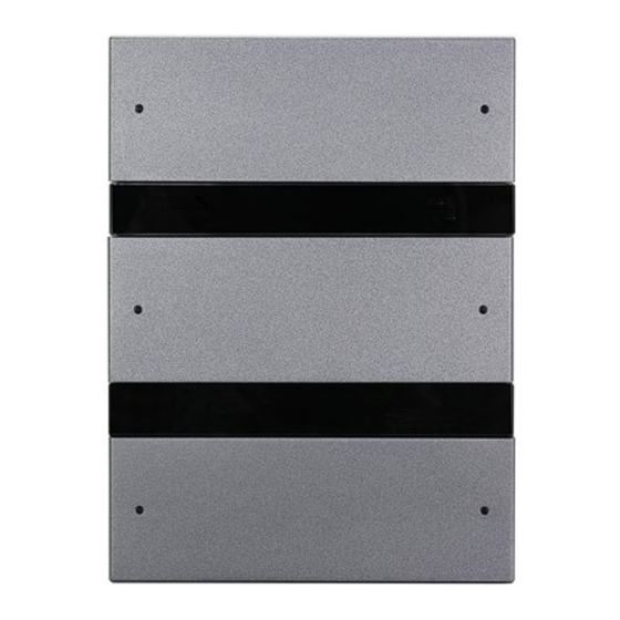
Figure 1. M/P2R.1
Customizable label
21mm
86mm
11mm
A1
1
2
3
A4
Figure 3
Figure 4
M/P2R.1
Figure 3 - 5. Dimensions
21mm
11mm
86mm
A1
A6
Figure 7
Figure 6
M/P3R.1
Figure 6 - 8. Dimensions
Overview
KNX Granite (See Figure 1-2)
bedded with RGB light for each button. Any color and brightness of label backlight and button indicator
can be set in ETS software.
Functions
Mechanical buttons and button backlights are available;
■
Supports button work modes: Left & right button combination mode or independent button mode;
■
Adjustable color and brightness of the label backlight and button indicator;
■
Supports multiple control modes: Switch control, dimming control, Shutter control, Flexible control,
■
Scene control, Sequence control, Percentage control, Threshold control, String (14 bytes) control,
Alternate control, RGB control, Fan control, Thermostat control, Combination control;
With built-in temperature probe, the panel can automatically obtain the temperature information;
■
The button indicator can be displayed mutual exclusively;
■
Press the top left corner and the lower right corner button(A1 and A4 for M/P2R.1, A1 and A6 for M/
■
P3R.1) simultaneously for 2 seconds, the panel will enter programming mode.
Important Notes
The panel must be wall box mounted.
■
It must work in conjunction with the power interface (M/PCI.1-A in conjunction with EU panel, M/
■
PCI.3-A in conjunction with US panel).
The device is compliant with KNX standard and the parameters are set by the Engineering Tool
■
Software (ETS).
Product Information
Dimensions - See Figure 3 - 8
1. Control button: It is used to control the status of the targets
2. Label backlight: It is for label backlight. The brightness can be automatically adjusted. The color and
Figure 2. M/P3R.1
brightness of the indicator can be customized by user.
3. Button indicator: It is used to indicate the status of the targets. The color and brightness of the indicator
can be customized by user.
4. Communication interface: It connects to panel power interface.
5. Fastener: It connects to panel power interface.
Programming: Press the top left corner and the lower right corner button(A1 and A4 for M/P2R.1, A1 and
A6 for M/P3R.1) simultaneously for 2 seconds, the panel will enter programming mode.
Product installation and disassembly (Take M/P2R.1 as an example)
60mm
Installation - See Figure 9 - 11
Step 1. Fix the power interface into the wall box with screws.
4
Step 2. Hold the edge of the panel, then insert the panel into the power interface module vertically.
Disassembly - See Figure 12
5
Step 1. Insert the panel gap with a slotted screwdriver.
Step 2. Pry up the panel gently and hold the edge panel. Then the panel can be taken off.
Figure 5
Glass replacement - See Figure 13 - 16 (Take M/P3R.1 as an example)
Step 1. Insert the split gap on the left and right of the metal covers and the right split gap of the glasses
with a slotted screwdriver, and pry gently, then remove the metal covers and glasses.
Step 2. Align the new glasses and the original metal covers with the panel buckle and gently press to
complete the glass replacement.
Safety Precautions
The installation and commissioning of the device must be carried out by HDL or the organization
■
designated by HDL. For planning and construction of electric installations, the relevant guidelines,
regulations and standards of the respective country are to be considered.
60mm
The device should be wall box mounted. HDL takes no responsibility for all consequences caused by
■
installation and wire connection which are not in accordance with this document.
Please do not privately disassemble the device or change components, otherwise it may cause
■
mechanical failure, electric shock, fire or body injury.
Please resort to our customer service department or designated agencies for maintenance service.
■
The warranty is not applicable for the product fault caused by private disassembly.
Figure 8
Package Contents
M/P2R.1 or M/P3R.1*1 / Datasheet*1
is a multi-function panel, which supports multiple control modes. It is em-
1/2
Advertisement

Related Manuals for HDL M/P2R.1

Summary of Contents for HDL M/P2R.1
- Page 1 The button indicator can be displayed mutual exclusively; ■ File Edition: V1.0.0 Press the top left corner and the lower right corner button(A1 and A4 for M/P2R.1, A1 and A6 for M/ ■ P3R.1) simultaneously for 2 seconds, the panel will enter programming mode.
- Page 2 Standard IEC62321-2015. KNX Cable Guide KNX Cable Technical support E-mail: hdltickets@hdlautomation.com Black Website: https://www.hdlautomation.com ©Copyright by HDL Automation Co., Ltd. All rights reserved. Specifications subject to change without notice.