Advertisement
Quick Links
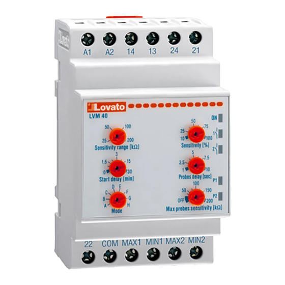
14
13
24
21
A1
A2
Lo va t o
LVM40
1
2
50
50
100
75
25
1
10
100
25
200
Sensitivity range [Kohm]
Sensitivity [%]
2
3
3
4
5
7,5
15
1.5
2,5
0
30
1
10
Start delay [min]
Probes delay [sec]
P1
100
D
E
5
F
6
C
50
150
B
G
P2
A
H
OFF
200
Mode
Max probes sensitivity [kohm]
22
COM
MAX1
MIN1
MAX2
MIN2
Schemat połączeń
Wiring diagram
Uwaga:
Zaciski sondy COM mogą być
podłączone bezpośrednio do zbiornika
jeśli jest wykonany z materiału
przewodzącego.
NOTE:
The "COM" terminal can be directly
connected to the tank if it is made of a
conductive material.
I162 PL GB 1104 LVM40
PL
PRZEKANIK POZIOMU
DLA PŁYNÓW
PRZEWODZĄCYCH
LVM40
UWAGA! W celu uniknięcia uszkodzeń i
zagrożenia urządzenia te muszą być
instalowane przez wykwalifikowany personel,
zgodnie z obowiązującymi standardami.
Produkty zaprezentowane w tym dokumencie są zgodne z
naszą aktualną ofertą, ale zastrzegamy sobie prawo do
wprowadzenia zmian bez wcześniejszego powiadomienia.
Dane i opisy wyszczególnione w tym dokumencie nie mają
wartości kontraktowej, więc nie odpowiadamy za powstałe
błędy lub pominięcia.
Opis
-
Kontrola poziomu płynów przewodzących
-
5 programowalnych funkcji:
A: Opróżnianie z alarmami extra-min i
extra-max
B: Napełnianie z alarmami extra-min i
extra-max
C: Opróżnianie ze zmianą pompy
D: Napełnianie ze zmianą pompy
E: Napełnianie zbiornika ze studni
F-G-H: nie funkcje
-
5 elektrod COM, MAX1, MIN1, MAX2,
MIN2 (do zakupu osobno)
-
Potencjometr dla 4 zakresów regulowanych
czułości (25, 50, 100, 200kΩ)
-
Potencjometr procentowy czułości
10..100% skali
-
Zakres czułości 2,5...200kΩ
-
Osobna regulacja czułości sondy MAX dla
płynów pieniących
-
Regulowane opóźnienie sygnału sondy
1..10s
-
Regulowane opóźnienie rozruchu pompy
0..30min
-
2 wyjścia przekaźnikowe (1 NO + 1
przełaczny)
-
Zielona LED dla zasilania
A1
-
2 LED do stanu przekaźnika
-
2 LED do stanu sondy
A2
Wskazania LED
Zielona dioda LED wskazuje włączone zasilanie.
Dwie czerwone diody LED wskazują:
- Stan przekaźnika 1 (styki NO na zaciskach 13
i 14)
- Stan przekaźnika 2 (styki przełączne na
zaciskach 21, 22 i 24)
Kiedy dioda przekaźnikowa LED miga znaczy
to iż minął czas opóźnienia zadziałania. Po
tym, przekaźnik jest w stanie zadziałania i
dioda LED świeci ciągle.
Diody LED P1 i P2 wskazują stan par elektrod
MAX1, MIN1 i MAX2, MIN2.
- LED wyłączone kiedy obie sondy są suche
- LED migające kiedy MAX jest sucha i MIN
jest mokra
- LED włączone kiedy obie sondy są mokre.
Regulacja czułości
Regulacji czułości dokonuje się przy pomocy
potencjometrów [1] – skala, i [2] – procentowo.
MULTIFUNCTION
LEVEL RELAY
FOR CONDUCTIVE LIQUIDS
CAUTION! This equipment must be installed by
qualified personnel, complying with current
standards, to avoid damages or safety hazards.
Products illustrated herein are subject to alterations
and changes without prior notice. Technical data and
descriptions in the documentation are accurate to the best
of our knowledge, but no liabilities for errors, omissions, or
contingencies arising there from are accepted.
Description
Level control for conductive liquids
-
5 programmable functions:
-
A: Emptying with extra minimum and extra
maximum alarms
B: Filling with extra minimum and extra
maximum alarms
C: Emptying with pump change
D: Filling with pump change
E: Tank filling from well drawing
F-G-H: No functions
Detection by means of electrodes COM,
-
MAX1, MIN1, MAX2, MIN2, to be purchased
separately
Rotating selector for 4 sensitivity range
-
adjustment scales: 25, 50, 100, 200kΩ
Sensitivity percentage potentiometer:
-
10...100% of regulated scale value
Maximum probe sensitivity adjustment range:
-
2.5...200kΩ
Max electrode with independent sensitivity
-
adjustment for foaming liquids
Adjustable PROBE time delay: 1...10sec
-
Adjustable START time delay: 0...30min
-
2 output relays, 1N/O + 1 changeover
-
Indication LED for power ON
-
2 indication LEDs for relay status
-
2 indication LEDs for probe status.
-
LED indications
The green LED indicates power supply on.
The two upper red LEDs respectively indicate:
- Relay 1 status: N/O contact of terminals 13 and
14
- Relay 2 status: changeover contact of terminals
21, 22 and 24.
When the relay LED is flashing, the tripping time
delay is lapsing. After that, the relay is energised
and the LED is constantly lighted.
P1 and P2 LEDs respectively indicate the status
of the pair of electrodes MAX1-MIN1 and
MAX2-MIN2.
- LED switched off when both probes are not
wet.
- LED flashing when MAX is not wet and MIN is
wet
- LED switched on when both probes are wet.
Sensitivity adjustment
The sensitivity adjustment is obtained by
selecting the scale with rotating selector [1] and
then adjusting the percentage with potentiometer
[2].
10/09/2004
1/ 5
Page
Advertisement

Related Manuals for LOVATO ELECTRIC LVM40


Summary of Contents for LOVATO ELECTRIC LVM40
- Page 1 The sensitivity adjustment is obtained by Regulacji czułości dokonuje się przy pomocy selecting the scale with rotating selector [1] and potencjometrów [1] – skala, i [2] – procentowo. then adjusting the percentage with potentiometer [2]. 1/ 5 I162 PL GB 1104 LVM40 10/09/2004 Page...
- Page 2 Wykres działania (TYP A) - Operational diagram (MODE A) Relè 1/ Relè 2/ (1) Opóźnienie sondy + opóźnienie startu / PROBE delay + START delay (2) Opóźnienie sondy / PROBE delay 2/ 5 I162 PL GB 1104 LVM40 10/09/2004 Page...
- Page 3 Wykres działania (TYP C) - Operational diagram (MODE C) Relè 1/ 5 sec Relè 2/ (1) Opóźnienie sondy + opóźnienie startu / PROBE delay + START delay (2) Opóźnienie sondy / PROBE delay 3/ 5 I162 PL GB 1104 LVM40 10/09/2004 Page...
- Page 4 Wykres działania (TYP E) - Operational diagram (MODE E) Serbatoio/ Pozzo/ Relè 1/ Relè 2/ 21 (1) Opóźnienie sondy + opóźnienie startu / PROBE delay + START delay (2) Opóźnienie sondy / PROBE delay 4/ 5 I162 PL GB 1104 LVM40 10/09/2004 Page...
-
Page 5: Dane Techniczne
Długość kabla może być redukowana jeśli jeśli przekrój kabla The total cable length can be reduced if cable section is jest większy i jeśli użyto kabla o większej ilości żył. greater or a higher number of cores is used. 5/ 5 I162 PL GB 1104 LVM40 10/09/2004 Page...