Advertisement
Quick Links
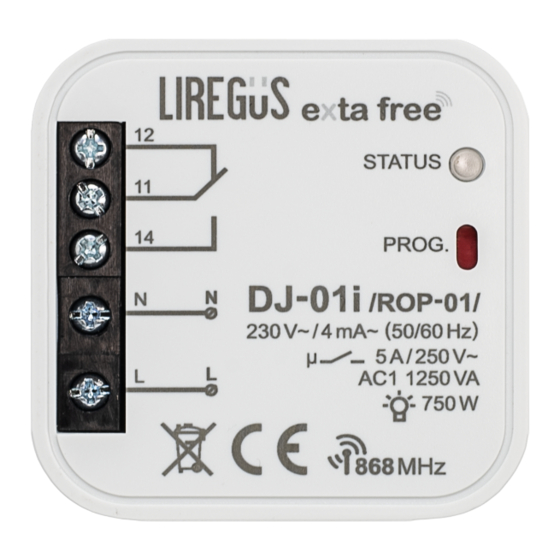
CONNECTION
APPLICATION
DJ-01s
/RNK-02/
WARRANTY CARD
There is 12 months guarantee on the product
1. LIREGUS provides a one-year warranty for its products.
2. The LIREGUS warranty does not cover: a) mechanical defects resulting from transport, loading / unloading or other circumstances
b) defects resulting from incorrect installation or operation of LIREGUS products; c) defects resulting from any changes made by CUS-
TOMERS or third parties, to products sold or equipment necessary for the correct operation of products sold; d) defects resulting
from force majeure or other aleatory events for which LIREGUS is not liable; e) power supply (batteries) to be equipped with a device
in the moment of sale (if they appear);
3. All complaints in relation to the warranty must be provided by the CUSTOMER in writing to the retailer after discovering a defect.;
4. LIREGUS will review complaints in accordance with existing regulations.;
5. The way a complaint is settled, e.g. replacement of the product, repair or refund, is left to the discretion of LIREGUS;
6. Guarantee does not exclude, does not limit, nor does it suspend the rights of the PURCHASER resulting from the discrepancy
between the goods and the contract.
Salesman stamp and signature, date of sale
MOUNTING
1. Disconnect power supply by the
phase fuse, the circuit-breaker or
the switch-disconnector combined
to the proper circuit.
2. Check if there is no voltage on
connection cables by means of
a special measure equipment.
3. Connect the cables with the termi-
nals in accordance with the install-
ing diagram.
4. Install DJ-01i
device in
/ROP-01/
installation cable box.
5. Switch on the power supply from
the mains.
CAPACITY
750W
500W
250W
375W
DJ-01i
1-channel
radio
receiver
/ROP-01/
DJ-01i
operates as a
/ROP-01/
receiver of 8-channel remote
cotroller P-256/8 and of 2-
channel button radio transmitter
DJ-01i /
(light sources
RNK-02/
switch on/switch off control).
The above mentioned trans
mitters can also control op
eration of radio lighting switch
RWL-01 and remote control
socket RWG-01.
1-CHANNEL RADIO RECEIVER
Skroblų g.19, 03141 Vilnius, Lietuva
tel. +370 5 233 6476, fax +370 5 216 1106
www.liregus.lt
DESCRIPTION
TECHNICAL DATA
Radio receivers are used both as el-
installation cable boxes and as an ac-
other receivers. DJ-01i
/ROP-01/
enables operation in 5 different modes
(switching on,s witching off, monostable
mode, bistable mode, time mode).
FEATURES
● cooperation with wireless EXTA FREE
control system transmitters,
● 1 NO/OC output relay (dry contacts),
Optical signalling of transmitter's operation: red LED diode
● lighting, heating operation control,
● easy junction box Ø 60 mm installation,
● 5 operation modes: switching on, swit-
ching off, monostable mode, bistable
mode, time mode (switch off delay),
● wide operation range (up to 230 m),
● operation is optically signalled,
● low current consumption, possibility of
constant operation,
● possibility of increasing operation ran-
ge by means of RTN-01 retransmitter.
The device is designed for
APPEARANCE
single-phase installation and
must be installed in accord-
ance with standards valid in
a particular country. The de-
vice should be connected
CAUTION
Relay output terminals
according to the details in-
cluded in this operating manual. Installation,
(12, 11, 14)
connection and control should be carried out by
-
ance with the service manual and the device
functions. Disassembling of the device is equal
Input (supply) terminals (L, N)
with a loss of guarantee and can cause elec-
tric shock. Before installation make sure the
connection cables are not under voltage. The
cruciform head screwdriver 3,5 mm should be
used to instal the device. Improper transport,
Optical signalling of receiver's operation
wrong functioning. It is not advisable to instal
the device in the following cases: if any device
Programming buttons
part is missing or the device is damaged or de-
formed. In case of improper functioning of the
device contact the producer.
The symbol means selective
collecting of electrical and electronic
equipment. It is forbidden to put
the used equipment together with
other waste.
DJ-01i
MANUAL INSTRUCTION
LIREGUS, UAB
e-mail: info@liregus.lt
DJ-01i
/ROP-01/
Input (supply) terminals: L, N
Input rated voltage: 230 V AC
Input voltage tolerance: -15 ÷ +10 %
Nominal frequency: 50 / 60 Hz
Nominal power consumption: 0,29 W
Number of operation modes: 5
Number of channels: 1
Transmission: radio 868,32 MHz
Transmission way: unidirectional
Coding: addressing transmission
Maximum number of transmitters: 32
Range: up to 230 m in the open air
Time adjustment: 1 second ÷ 18 hours (every second)
Relay output clamps: 12, 11, 14
Relay contacts parameters: 1NO/NC 5A / 250V~ AC1 1250 VA
Number of terminal clamps: 5
Section of connecting cables: up to 2,5 mm
2
Ambient temperature range: -10 ÷ +55
o
C
Operating position: free
Casing mounting: junction box Ø 60 mm
Casing protection degree: IP20 (EN 60529)
Protection level: II
Overvoltage category: II
Pollution degree: 2
Surge voltage: 1 kV (EN 61000-4-5)
Dimensions: 47,5 x 47,5 x 20 mm
Weight: 0,043 kg
Reference standard: EN 60669, EN 60950, EN 61000
/ROP-01/
VER. 001_30.08.2017
Advertisement

Summary of Contents for LIREGUS DJ-01i
- Page 1 TOMERS or third parties, to products sold or equipment necessary for the correct operation of products sold; d) defects resulting device contact the producer. from force majeure or other aleatory events for which LIREGUS is not liable; e) power supply (batteries) to be equipped with a device in the moment of sale (if they appear);...
- Page 2 After 5 seconds LED red diode switches on Release the push-button in ROP-01 - for a longer time. (signal pulsates) and then it switches off. MEMORY IS DELETED. MONOSTABLE mode: COOPERATION AND OPERATION RANGE DJ-01i Symbol ROP-02 ROB-01 SRP-02 SRP-03 RWG-01 RWL-01 ROM-01 ROM-10...