Advertisement
Quick Links
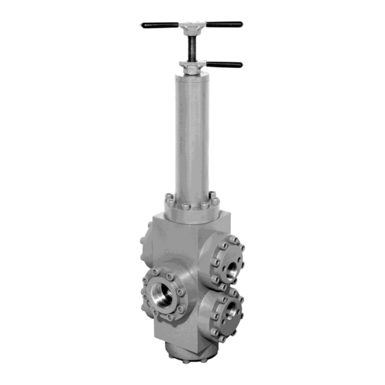
MAINTENANCE INSTRUCTIONS
KR-150 Regulator
Only qualified personnel should perform maintenance.
Be sure that system pressure has been VENTED prior to disassembly.
All instructions, illustrations and item numbers refer to the
manual operated regulator, 40-1698. Refer to specific
installation drawing for corresponding items.
Repair Procedure
Preparation
1. Prepare a clean surface for disassembly, free of dust,
grease, grit, etc. A vise is not necessary, but helpful.
Have rags, degreasing solvent and lubricant available.
2. Critical surfaces to protect during disassembly are the
inside diameter of the piston guide 30, the inside
diameters of the seal container 28, the flat sealing
surfaces of the seal rings 11 and 13 and the flat
surfaces of the flow plates 23 and 24. Lapped surfaces
should NEVER come in contact with any hard surface.
3. All O-rings and back-up rings are recommended to be
replaced at a minimum. See the parts list for kit
contents.
4. Special tools used in assembly include a blunt ended
rod for seating backup rings, (step 4), medium strength
(blue) threadlocker (step 7) and a flat spacer about
3/16" thick for reinstalling the inlet and vent flanges
(step 8 and 10).
Disassembly
1. To relieve the compression on the internal operator
springs (20, 21) loosen the lock handle 17 and rotate
the adjustment handle 18 counter-clockwise until the
resistance is fully relieved. Springs must be loose to
safely remove the adjustment head.
Rev A
Tel: 714-529-9495
Fax: 714-529-1366
561 Tamarack Ave, Brea CA USA
pacsealhydraulics.com
Advertisement

Summary of Contents for PACSEAL HYDRAULICS KR-150
- Page 1 MAINTENANCE INSTRUCTIONS KR-150 Regulator Only qualified personnel should perform maintenance. Be sure that system pressure has been VENTED prior to disassembly. All instructions, illustrations and item numbers refer to the manual operated regulator, 40-1698. Refer to specific installation drawing for corresponding items.
- Page 2 Maintenance Instructions KR-150 Regulator 2. With a 5/16” Allen wrench, loosen and remove Reassembly the socket head cap screws. Remove the 1. Before replacing the seals and rebuilding the adjustment head 27 and spring assembly by lifting and tilting and holding the spring plate 16 regulator, apply a light coating of lubricant.
- Page 3 Maintenance Instructions KR-150 Regulator ID Part # Description 1 23-1126 O-RING 2 23-1263 O-RING 3 23-1319 O-RING 4 23-1322 BACK-UP RING 5 23-1323 O-RING 6 23-1325 O-RING 7 23-1331 BACK-UP RING Actual model not shown 8 23-1332 O-RING 9 23-1334 O-RING 10.
- Page 4 Maintenance Instructions KR-150 Regulator KR-150 Manual Operated Regulator 40-1968 Rev A Page 4 Tel: 714-529-9495 Fax: 714-529-1366 561 Tamarack Ave, Brea CA USA pacsealhydraulics.com...
-
Page 5: Maintenance Instructions
MAINTENANCE INSTRUCTIONS KR-150 Regulator Technician Notes: Troubleshooting The KR regulators with manual operation in general are not a precision device. There are large friction forces from the shear seals which are balanced by the springs. There is constant movement within the valve which translates into observed pressure fluctuations.