Advertisement
Quick Links
S.a.s. di Guazzetti Giovanni & C.
COSTRUZIONI MECCANICHE ELETTRICHE
Installation and Maintenance Rules for:
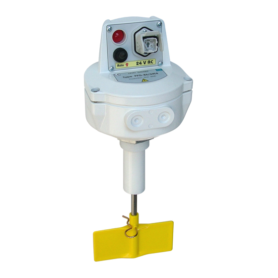
Bladed level gauges PFG-86
PFG-86 - PFG-86/F - PFG-86/C - PFG-86/X - PFG-86/X/F
STANDARD FEATURES
The PFG-86 level gauge is made in compliance with the regulations in force in the European Union and specifically with:
- Die-cast aluminium casing UNI 5076. IP65 protection.
- Stainless steel shaft on ball bearings, watertight with permanent lubrication, with neoprene Corteco ring for dust sealing.
- Standard Nylon screw, on request made of stainless steel or other materials and versions with 1, 2, 3 or 4 blades.
- Electrical construction in compliance with Directives 2014/35/EU (low-voltage electrical material) and 2014/30/EU (electromagnetic
compatibility).
- Noise level measured in open field: zero.
- Motor absorption: 4 Watts.
ATEX MARKING: II 1/2 D Ex ta/tb IIIC T85°C Da/Db
II
Group II, intended for use in surface industry.
1/2 D
Suitable for Cat. 1 - Zone 20 inside silos (shaft with screw); Cat. 2 – Zone 21 external (indicator casing).
Ex ta/tb
Protection method Ex t - protected against dust (ta internal / tb external).
IIIC
Dust group C (suitable for operation in presence of all types of dust, conductives included).
T85°C
Temperature class - maximum superficial temperature of the device 85°C.
Da/Db
Equipment Protection Level for dust atmospheres. Da (very high) for zone 20 (internal); Db (high) for zone 21 (external).
SAFETY RULES
All the appropriate safety precautions must be taken when electrically operated equipment is used, in order to reduce
the risk of fire outbreaks, electric shock and injuries to persons.
- Keep the work zone clean and orderly. Accidents are more likely to occour in untidy areas and environments.
- Before beginning work, make sure that the level gauge is in a perfect condition. Damaged or broken parts must be
repaired or replaced by competent personnel authorized by the Manufacturer.
- All verifications, inspections, cleaning and maintenance operations, part changes and replacements must be carried
out with the level gauge disconnected and the plug removed from the power socket.
- It is absolutely forbidden for children, unauthorized and/or inexpert persons to touch or use the level gauge.
- Make sure that the electricity system complies with the laws in force. Make sure that the earthing is efficiently
connected when the instrument is installed. Check to be sure that the power socket is suitable, that it complies
with the laws in force and that it has a build in automatic protection circuit-breaker.
- The level gauge must never be stopped by detaching the plug from the power socket. Moreover, never use the
cable to pull the plug from the socket.
- Periodically check to be sure that the cable is in a perfect condition and replace it if damage is discovered.
This operation must only be carried out by competent and authorized persons. Only use extensions cables of the
permitted type and marked.
- Protect the cable against high temperatures, lubricants and sharp edges. Do not twist or knot the cable.
- Do not allow children or unauthorized persons to touch the cable when the instrument is plugged in.
INSTALLATION
Before installation, inspect the outer structure of the level gauge. Check the movement of the screw shaft and
the operation of the clutch assembly. If this check reveals anything irregular, the level gauge must be sent to
CAMLogic to be restored to efficiency. CAMLogic level gauges can be installed in any position. With the shaft in a
REGGIO EMILIA ( Italy )
PIENO
0
1
110
2
M
220
3
4
10A.250V.c.a.
5
6
7
BREVETTO
N. 656961
VUOTO
PFG 86
Tipo
N.
Fig.1
The level gauge can be mounted on the silos by the standard connection with threaded sleeve ( 2" 1/2 Gas ) to be
welded onto the silos ( PFG-86 ) or by flange connection with 6MA screws ( PFG-86/F ). These two methods involve
no modifications to the level gauge since the flange uses the thread on the body of the gauge envisaged for the
sleeve. When mounting with the sleeve, the gauge must be fully screwed onto the sleeve, then it is necessary to
turn it to obtain an upright position of the wiring plate, then tighten the securing screw on the threaded sleeve.
R
Via dell' Industria 12 - 12/A - 42025 CAVRIAGO - RE - Italy
Tel. 0522942641 - 0522941172 - Fax 0522942643
www.camlogic.it
- Envisaged power supplies: 110/220 VAC or 24/48 VAC 50/60 Hz - 24 VDC.
- Use contact capacity: 10 A. at 250 VAC.
horizontal or sloping position, the level gauge must
be mounted with the wiring plate inside the casing
in an upright position and the cable passages on
the right-hand side ( Fig.1 ).
The level gauge is mounted on the chambers or
silos, on the side or top.
It is important to choose the position so that
the device is not hit by the falling load, likewise
taking care that the material can move freely all
around the gauge. Protective deflectors ( Fig.2 )
are advisable when there is considerable weight
weighing on the shaft or when material that flows
badly is likely to move in a block.
e-mail camlogic@camlogic.it
- Output speed (screw shaft): 1rpm.
Fig.2
00625 97.06 - Rev. 05
Advertisement

Related Manuals for Camlogic PFG-86


Summary of Contents for Camlogic PFG-86
- Page 1 The level gauge can be mounted on the silos by the standard connection with threaded sleeve ( 2" 1/2 Gas ) to be welded onto the silos ( PFG-86 ) or by flange connection with 6MA screws ( PFG-86/F ). These two methods involve no modifications to the level gauge since the flange uses the thread on the body of the gauge envisaged for the sleeve.
- Page 2 DECLARATION OF CONFORMITY The manufacturer CAMLogic declares under its own responsability that the product PFG-86/./././. answers to the requisites of the European Directive 2014/34/EU in consideration of the standards : EN IEC 60079-0:2018 and EN 60079-31:2014. The permitted ambient temperature range is -20 to +70 °C.