Advertisement
Available languages
Available languages
Quick Links
QwikSwap™ V3 (QT6104) Installation Guide
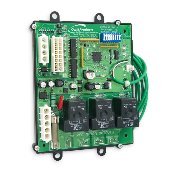
Variable Speed ECM to PSC Motor conversion (for 2.0, 2.3, 2.5, 3.0 ECM and EMERSON VSM Motors Only)
ECM
2.0, 2.3, & 2.5
CONFIGURATION
CONNECTOR
SWITCHES
ECM 3.0
& EMERSON
VSM
STATUS LED
LOW SPEED
MED SPEED
HIGH SPEED
MOTOR POWER
LED
LED
LED
(120VAC or 240VAC)
TO PSC MOTOR HIGH SPEED
TO PSC MOTOR MEDIUM SPEED
TO PSC MOTOR COMMON
TO PSC MOTOR LOW SPEED
INSTALLATION INSTRUCTIONS
1
Identify defective ECM version using label or pictures below.
ECM 2.0, 2.3:
ECM 2.5:
16-pin connector uses most
16-pin connector uses only
pins.
4 pins.
Identify ECM motor voltage to select proper PSC
2
replacement motor.
Examine 5-pin power connector on defective ECM motor.
X
Jumper wire between pin 1 and pin 2: 120 VAC replacement PSC motor required.
X
No jumper wires: 240 VAC replacement PSC motor required.
www.qwik.com/qwik-swap
200 Yellow Place, Rockledge, FL 32955 / 321-631-3550
All marks shown within this document are properties of their respective owners, X13® is a registered
Trademark of Regal Beloit®. SelecTech®, Emerson®, U.S. Motors® and Nidec® are registered trademarks
of Nidec Motor Corporation. QwikProducts™, QwikSwap™ and U.S.A. INNOVATION ™ are
trademarks of Mainstream Engineering Corporation®, Rockledge, Florida 32955, (321) 631-3550
© 2016 Mainstream Engineering Corporation® / Protected by U.S. Patent #9,207,001, other
U.S.A. INNOVATION
Patents Pending
GLOSSARY
MOTOR POWER: 5-pin connector accepts 120 VAC or 240 VAC
connector from defective ECM motor.
COMMUNICATION
TO PSC MOTOR (COMMON, LOW SPEED, MEDIUM SPEED, and
LED
HIGH SPEED): Connections to PSC motor.
ECM 2.0, 2.3, & 2.5 CONNECTOR: 16-pin signal connector accepts
connector from defective 2.0, 2.3 or 2.5 ECM motor.
ECM 3.0 & EMERSON VSM: 4-pin signal connector accepts
DELAY LED
connector from defective 3.0 ECM or Emerson VSM motor.
CONFIGURATION SWITCHES: Used to program QwikSwap™ V3.
LOW, MED, HIGH SPEED LEDs: Solid
GREEN
PSC motor speed tap is energized.
STATUS LED: Flashing
YELLOW
LED indicates QwikSwap™ V3 is
receiving line power.
COMMUNICATION LED: Solid
RED
LED indicates successful
communication with the blower motor's control board. OFF or
RED
flashing
indicates a communication problem, such as a failed
ECM air handler control board, faulty wiring or some other issue that
will prevent the QwikSwap™ V3 from operating properly.
proceed with the installation unless this problem can be resolved.
DELAY LED: Solid
BLUE
LED indicates a delay-on-break is keeping
the blower motor operating (for 3 minutes) after the blower motor
has been commanded to turn OFF (2.0 and 2.3 motors only).
ECM 3.0:
EMERSON VSM:
4-pin signal connector
4-pin signal connector
™
DETERMINING REPLACEMENT PSC MOTOR VOLTAGE
3
Verify QwikSwap™ V3 communications
Prior to replacing the defective ECM motor with a QwikSwap™ V3 board and a PSC motor,
perform the following steps to verify proper performance when installed.
Turn thermostat system to OFF and FAN control to OFF.
a.
Turn all humidity controls to OFF.
b.
c.
Disconnect power to the air handler.
d.
Remove the 5-pin power plug and 16-pin (2.0, 2.3 & 2.5) or 4-pin (3.0 & Emerson VSM) signal plug
from the defective ECM motor and reconnect to the mating connectors on the QwikSwap™ V3.
e. For ECM 2.5, 3.0, and Emerson VSM motors only:
the rated horsepower of the defective ECM motor.
CONFIGURATION SWITCH NUMBER & POSITION
H.P.
1
2
1/8
ON
OFF
OFF
1/4
ON
ON
OFF
1/3
ON
ON
ON
1/2
ON
ON
ON
LEDs indicate which
2/3
ON
ON
ON
3/4
ON
ON
ON
1
ON
ON
ON
Reconnect power to the air handler. Leave the thermostat, blower and humidity controls OFF.
f.
NOTE:
THE EXISTING SYSTEM'S BLOWER CONTROL BOARD IS CONNECTED TO THE QWIKSWAP, BUT THE
QWIKSWAP IS NOT CONNECTED TO ANY MOTOR AT THIS TIME.
A flashing
YELLOW
g.
(STATUS) LED and solid
Do not
proceed to the next step.
X
OFF
YELLOW
(STATUS) LED: verify 120/240 VAC power to the QwikSwap™ V3 board.
X
OFF or flashing
RED
(COM) LED indicates a communication problem between the existing
air handler board and the QwikSwap™ V3. OFF
motors may indicate a problem with the 24 VAC signal from the air handler board or the
transformer.
Do not proceed with the installation, unless the problem can be resolved.
X
GREEN
(SPEED) LEDs should be OFF at this time.
For ECM 2.5, 3.0, and Emerson VSM motors only: During flashing
solid
RED
(COM) LED, set all CONFIGURATION SWITCHES to OFF to lock-in the Input Configuration. If
this QwikSwap™ V3 board is to be used in a different unit, see
CONFIGURATION
before reusing the QwikSwap™ V3 in a different unit.
h.
Set the thermostat to FAN ON.
Following a short delay (which can take several minutes for the air handler board to send a
i.
command), the
GREEN
(HIGH) LED should initially light, and then settle on one of the
(HIGH), (MED), or (LOW) LEDs. Operate the unit for a few minutes to make sure the air handler
control board has accepted the QwikSwap™ V3 communication.
THE QWIKSWAP IS NOT CONNECTED TO ANY MOTOR AT THIS TIME
Set FAN control to OFF at the thermostat. Within a few minutes the QwikSwap™ V3 should receive
j.
a request to turn OFF, and all the
GREEN
For 2.0 and 2.3 ECM motors only:
X
Solid
BLUE
(DELAY) LED and one solid
delay-on-break is active. Both LEDs should go OFF after the 3-minute delay.
GREEN
LED is ON and the
X
If the
time to deactivate the blower has passed) see
CONFIGURATION.
DO NOT PROCEED WITH THE INSTALLATION IF THIS CANNOT BE RESOLVED.
k.
Once all the steps above have been confirmed, proceed to Step 4 to complete the installation of the
PSC motor with the QwikSwap™ V3.
4
Complete QwikSwap™ V3 and PSC motor installation.
Having confirmed successful communication between the QwikSwap™ V3 and the existing
air handler control board, perform the following steps to install and wire the PSC motor.
Disconnect power to the air handler.
a.
b.
Remove defective ECM motor (note the direction of rotation and motor voltage).
c.
Install new PSC motor (with same voltage and direction of rotation) and PSC motor capacitor.
Connect the PSC motor common wire to the MOTOR COM terminal on the QwikSwap™ V3. This
d.
wire is typically WHITE. Verify with replacement PSC motor instructions.
e.
Connect the three PSC motor speed taps to the corresponding terminals on the QwikSwap™ V3.
For most PSC motors:
RED
– MOTOR LOW,
with replacement PSC motor instructions.
f.
Attach the temperature sensor bulb to an elbow closest to one of the inlet distribution lines on the
evaporator coil using the mounting hardware provided.
4
continued...
Use the CONFIGURATION SWITCHES to select
g.
Mount the QwikSwap™ V3 (directly or use the 90-degree mounting bracket) and dress all
wiring (so that no wires can be drawn into the fan or motor shaft and where the board and
wiring will not short out).
3
4
5
6
7
8
h.
Reconnect power to the air handler and verify proper operation.
OFF
OFF
OFF
OFF
OFF
OFF
OFF
OFF
OFF
OFF
APPENDIX 1: ADJUSTING THE INPUT CONFIGURATION
A
OFF
OFF
OFF
OFF
OFF
1
(For 2.0 & 2.3 ECM motors only)
ON
OFF
OFF
OFF
OFF
ON
ON
OFF
OFF
OFF
In rare cases, one or more of the blower motor activation signals may need to be ignored to prevent
the blower motor from operating continuously. Follow this procedure when a
ON
ON
ON
OFF
OFF
but it should be OFF. To adjust the configuration, set FAN control at the thermostat to OFF. The
ON
ON
ON
ON
ON
YELLOW
STATUS LED should be flashing. One of the
LED should not be lit. IF THE
ON-BREAK MODE AND THE QWIKSWAP V3 SHOULD TURN OFF WITHIN 3 MINUTES, REQUIRING NO
ADJUSTING OF THE INPUT CONFIGURATION.
RED
DO NOT TOUCH COPPER TRACES OR CONNECTIONS ON THE BOARD.
(COM) LED indicate proper communication,
Step 1.
While the QwikSwap™ V3 is connected and powered, set all CONFIGURATION SWITCHES to OFF.
While the QwikSwap™ V3 is connected and powered, set all CONFIGURATION SWITCHES to:
Step 2.
RED
(COM) LED for 2.0 and 2.3 ECM
1
ON
Step 3.
If the input configuration has been accepted, all of the
YELLOW
(STATUS) LED and
RED
(COM) LED and
still ON, repeat Steps 1-3.
APPENDIX 2: CLEARING THE INPUT
Step 4.
Once the configuration has been set, and while the QwikSwap™ V3 is still powered, turn all
CONFIGURATION SWITCHES to OFF to lock-in the setting. The
YELLOW
(STATUS) LED should be flashing to indicate success. All other LEDs should be OFF.
the
GREEN
APPENDIX 2: CLEARING THE INPUT CONFIGURATION
A
2
(For 2.0 & 2.3 ECM motors only)
This procedure should only be required if the QwikSwap™ V3 was previously installed in another
(HIGH, MED, LOW) should turn OFF.
system or an input configuration was accidently set. This procedure will clear the input configuration
stored memory.
GREEN
LED are both ON: indicates the 3-minute
DO NOT TOUCH COPPER TRACES OR CONNECTIONS ON THE BOARD.
BLUE
(DELAY) LED is OFF (even though sufficient
While the QwikSwap™ V3 is connected and powered, set all CONFIGURATION SWITCHES to OFF.
Step 1.
APPENDIX 1: ADJUSTING THE INPUT
Step 2.
While the QwikSwap™ V3 is connected and powered, set all CONFIGURATION SWITCHES to:
1
ON
If the INPUT CONFIGURATION has been successfully cleared, the
Step 3.
(DELAY) LED should be alternatively flashing. If not repeat Steps 1-3.
Once the input configuration has been cleared, set all CONFIGURATION SWITCHES to OFF.
Step 4.
RED
(COM) LED should be solid ON and the
The
success. All other LEDs should be OFF.
!
Need Help?...
XCall 1-321-631-3550
XView an online video installation tutorial
at www.qwik.com/qwik-swap
XScan this code..........................
BLUE
– MOTOR MED, and BLACK – MOTOR HIGH. Verify
with your smartphone.
XChat online with "Live Help"
at our website.
Installing temperature sensor of the QwikSwap™ on the coil
GREEN
LED is ON
GREEN
BLUE
LEDs should be lit and the
(DELAY)
BLUE
(DELAY) LED IS LIT THE QWIKSWAP V3 IS CURRENTLY IN DELAY-
USE AN INSULATED TOOL.
SWITCH SETTINGS
2
3
4
5
6
7
8
OFF
ON
ON
OFF
ON
OFF
ON
GREEN
LEDs should turn OFF and the
BLUE
(DELAY) LED should be flashing alternatively. If any of the
GREEN
LEDs are
RED
(COM) LED should be solid ON and
USE AN INSULATED TOOL.
SWITCH SETTINGS
2
3
4
5
6
7
8
OFF
ON
OFF
ON
OFF
OFF
ON
RED
(COM) LED and
BLUE
YELLOW
(STATUS) LED should be flashing to indicate
Installation Guide, Revision 1.5, August 2016 / 5008217_REV-C / 1201840001
Advertisement

Summary of Contents for Mainstream Engineering QwikSwap V3
- Page 1 LED indicates successful Reconnect power to the air handler. Leave the thermostat, blower and humidity controls OFF. ON-BREAK MODE AND THE QWIKSWAP V3 SHOULD TURN OFF WITHIN 3 MINUTES, REQUIRING NO communication with the blower motor’s control board. OFF or ADJUSTING OF THE INPUT CONFIGURATION.
- Page 2 4 pines (3.0 y Emerson VSM) del motor ECM defectuoso y vuelva a conectarse al conector de de 120VAC, o 240 VAC de motor ECM defectuoso. acoplamiento rápido en el QwikSwap V3 Instalación de sensor de temperatura de la QwikSwap ™ en la serpentines e.