Advertisement
Quick Links
1A Bennett House, The Dean, Alresford, Hampshire, UK. SO24 9BQ
Tel: +44 (0)1962 736736 Fax: +44 (0)1962 736737 Email: sales@influxmeasurements.com
A GUIDE TO THE INSTALLATION, OPERATION & MAINTENANCE OF
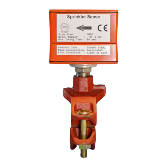
Flow Switches SPDB 30/90
FLOW SWITCHES IN AUTOMATIC SPRINKLER INSTALLATIONS
Contents:
1
1.1
1.2
1.3
2
2.1
2.2
3
3.1
3.2
4
4.1
4.2
T
- F
YPE
IREGROOVE
IOM SPDB Iss.2 ENG
M e a s u r e m e n t s L t d
24
T
YPE
March 2019
- F
IREFLANGE
Quality Systems Certificate No. 464
Assessed to ISO 9001:2015
Page
2
2
2
2
3
3
5
6
6
6
6
6
6
Page 1 of 6
Advertisement

Summary of Contents for INFLUX MEASUREMENTS SPDB 30
-
Page 1: Table Of Contents
1A Bennett House, The Dean, Alresford, Hampshire, UK. SO24 9BQ Tel: +44 (0)1962 736736 Fax: +44 (0)1962 736737 Email: sales@influxmeasurements.com A GUIDE TO THE INSTALLATION, OPERATION & MAINTENANCE OF Flow Switches SPDB 30/90 FLOW SWITCHES IN AUTOMATIC SPRINKLER INSTALLATIONS Contents: Page Specification &... -
Page 2: Specification & Principle Of Operation
24V D.C. Flow Switch Output: 1x DPCO Relay, 30V D.C., 2A Adjustable Delay: Type SPDB 30: 0 to 30 seconds Type SPDB 90: 0 to 90 seconds Flow-rate Sensitivity: The switch will operate at all flow-rates above 60 L/min The switch will not operate at flow-rates less than 10 L/min... -
Page 3: Installation
Installation Mechanical These switches may be mounted in horizontal or vertically up pipe run sections. The recommended arrangement is that the R ¾ mounting thread is connected to the pipe using suitable approved threaded Mechanical Tees and where required, a threaded reducing socket. This will allow fitting or removal of the switch without disconnecting the electrical connections. - Page 4 2.1.b Top and side mounting positions on horizontal pipe IOM SPDB Iss.2 ENG March 2019 Page 4 of 6...
-
Page 5: Electrical & Power Supply
Electrical & Power Supply Before installing the unit the flow signal delay timer can be set. Remove the top lid and locate the rotary position switch mounted on the PCB. Setting ‘0’ will select the minimum delay and setting ‘9’ the maximum delay. -
Page 6: Operation
Operation Flow The SprinklerSense flow-switch is designed to activate and maintain its switch relay output in the event of detecting a flow of water initiated by a sprinkler head becoming active or through operation of an inspector’s valve under test conditions. This switch output is delayed for a set duration based upon the delay time setting chosen at the installation stage.