Advertisement
Quick Links
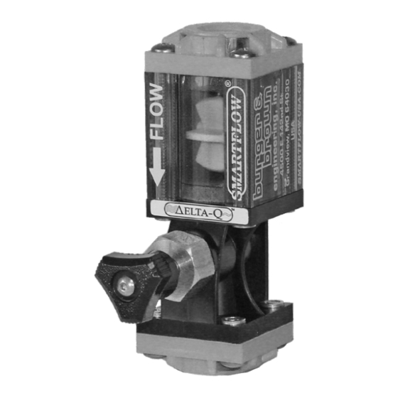
Low Flow Indicator
or
Low Flow Indicator with Delta-Q® Precision
Flow Regulator
Installation and Operating Instructions
Applies to: LFI3-A-40, LFI3B-A-40 or LFI3-A-40-Q, LFI3B-A-40-Q
General
Smartflow Low Flow Indicator is an in-line device using a high-visibility
impeller to show cooling media movement inside process cooling lines with
flow between 0.3 and 4 Liters per Minute.
Low flow Indicators are ideal for use in critical injection mold cooling
circuits using bubblers or baffles where flow is restricted and effective
cooling is essential.
The polysulfone flow body is compatible with common cooling liquids.
Wetted parts are made from corrosion-resistant materials in a proven design
platform.
Optional temperature and pressure gauges plus Delta-Q flow regulators can
be added as needed for increased functionality and suitability to process
requirements.
Specifications
Flow Range ......................................................0.3 - 4 LPM (0.08 - 1 GPM)
Connection size ...........................................1/4", 3/8" or 1/2" NPT or BSPP
Max. Temperature ................................................................... 210°F (99°C)
Max. Pressure ........................................................................100psi (6.9bar)
Component Materials
End Caps .......................................................... Brass or Glass-Filled Nylon
Flow Body .................................................................................. Polysulfone
Impeller ............................................................................................... Nylon
Shaft .......................................................................................Stainless Steel
O-Rings .............................................................................................. EPDM
Screws ....................................................................................Stainless Steel
Form #SF-217 (05.22)
Installation Best Practices
The flow indicator is line-mounted without additional
support.
1. For best results, install the flow indicator with 10
diameters of straight pipe before the inlet of the flow
indicator, and 5 diameters of straight pipe after the
outlet of the flow indicator.
2. Use a pipe thread sealant compatible with the
maximum operating temperature and process fluid.
Thread sealant must not contain solvent.
3. Cooling media should be clean and filtered to avoid
scale buildup inside the indicator. Impurities in the
water are likely to cause scale buildup in cooling
lines and deposits causing malfunction of the low
flow indicator.
4. Install the flow indicator with the arrow pointing in
the direction of flow.
4500 E 142nd Street • Grandview, MO 64030
Tel. (816) 878-6675 • www.smartflow-usa.com
Advertisement

Summary of Contents for Burger & Brown SMARTFLOW LFI3-A-40
- Page 1 Low Flow Indicator Low Flow Indicator with Delta-Q® Precision Flow Regulator Installation and Operating Instructions Applies to: LFI3-A-40, LFI3B-A-40 or LFI3-A-40-Q, LFI3B-A-40-Q General Smartflow Low Flow Indicator is an in-line device using a high-visibility impeller to show cooling media movement inside process cooling lines with flow between 0.3 and 4 Liters per Minute.
- Page 2 Low Flow Indicator Instructions Maintenance Debris in the circulating system may cause the impeller to stick or discolor the inside of the flow indicator body. Occasional cleaning of the internal Screws parts is recommended for optimum operation. End Cap Clean the flow body with mild, soapy water. DO NOT CLEAN WITH ACETONE or SOLVENTS.